Gearbox
-
Posts
74 -
Joined
Content Type
Profiles
Forums
Store
Articles
Gallery
Events
Library
Everything posted by Gearbox
-
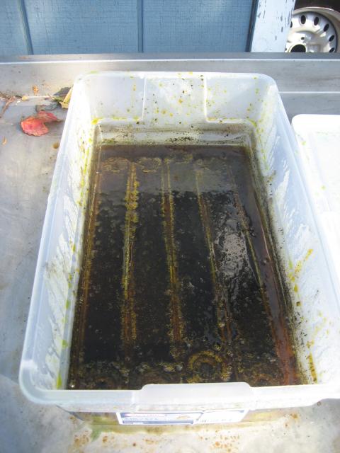
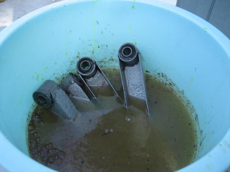
Just to let you know, all Evaporust is, is watered down Muriatic acid which is available at most hardware stores for 6 bucks a gallon. I've been using Muriatic acid on all my restorations for years. It attacks the rust and leaves the good metal behind. And it is fast. Depending on the size of the part, I use small tupperware tubs to those large plastic bins at home depot. For wheels, I found that those plastic round oil change pans perfect for 13" steel wheels, plus it has a spout to pour it back into the bottle. I normally will use full strength, and even if it doesn't fully submerge the part, I will flip it around every 20 minutes with rubber gloves and it cleans it in about a couple of hours. Just make sure you have a pail of clean water and baking soda to neutralize the acid. I use hot water with the baking soda so when you drop it in and once it stops fizzing, take it out and it dries quickly and minimizes any flash rusting. Just make sure you do not put anything aluminum in the acid, the reaction is pretty violent. You can reuse the acid for a long time, and once it gets too dirty, just dump a cup of baking soda into it and it neutralizes it within seconds for disposal. Good luck with you projects.

-
Hi Dean; Those were exactly what I found, anytime they had a 0.9370 or 0.9380 dia. cap, it immediately goes to 2.411" cap to cap. Seat one side with the circlip, and the opposite side cap blocks the circlip groove. The 0.970" by 2.411" is the standard U joint for the Anglia and everybody tells me that should be the correct joint, so I am still confused. As for the second source. I see that they have a 0.938 by 2.280". which is 1 thou larger in cap diameter, but too short by 30 thou side to side. I called them up and they told me that the 30 thou play was too much, and I brought up the possibility of shims, and they dissuaded me from that. Next step is to make custom joints, but would really like to know what drive shaft I have and was it a Lotus part.
-
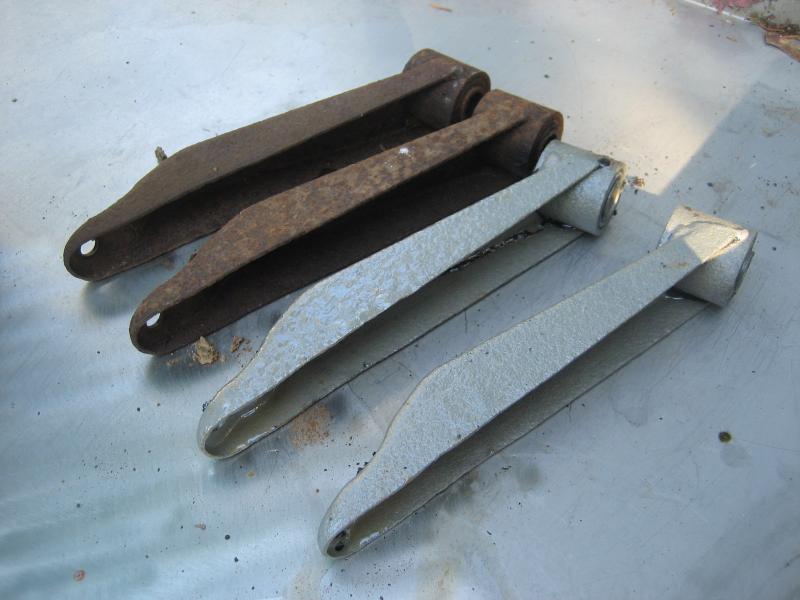
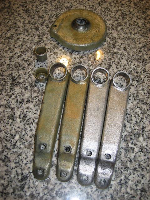
When the simple becomes a PITA. Not one of my favorite jobs, but never really had a problem with U Joints. Working on a 1962 Lotus Super Seven, Anglia 105e 977 gearbox and Standard 10 rear. I assume everything is original to the car including the prop shaft. Restored my drive shaft (prop shaft), got a new set of U joints from Bean, and pressed the old ones out. And of course, they were a nasty mess, so I tossed them. Then I noticed that the new U joints were too wide to allow the circlips on both sides to seat. Ok, pressed them out and started to measure. The U joints were the standard 0.937" cap diameters and outside cap to cap compressed was 2.41". But when I measured the dimension of the yokes, inside to inside between the circlips, I get 2.31", or about a full 0.100" difference. I measured all 4 yokes, and they all measure the same give or take a few thou. My first reaction was that I got the wrong U joints, but after talking with DB and searching the world for a U joint that would be close, they aren't any. Now I'm thinking that the yoke got squeezed together somehow when I removed the old joints, but it doesn't make sense as the measurement is the same 2.31" from the base of the yoke to the top. You would think the top would have squeezed in more if it distorted. Plus these yokes are cast iron, I would think if you moved them by 0.100" they would crack or something. So what am I missing here? I'm thinking I may have two options, either spreading the yoke or possibly milling off 0.050" from each tips of the spyders. I'm not crazy about spreading the yoke as that may crack the yoke or at minimum mis-align both sides. The milling would allow the caps to sit lower and it looks like the needle bearings will still have enough on the spyder for full contact, but the grease seals would be a bit squished. None of these are in any way close to optimum, but at a loss on what to do. Any ideas, or am I missing the obvious? Thanks Allan
-
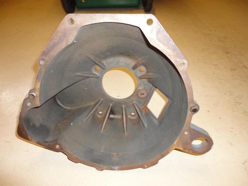
I wish it came from a Mustang or Pinto, then I could get the parts, but the bolt patterns are completely different for the Mustang or Pinto 3 or 4 speeds used at that time. Closest ID was a Cortina Mk2 with the 3014e marking, but no other info. What is the slave housing diameter on yours? Have a Pic? Thanks Allan PS what car did it come out of?
-
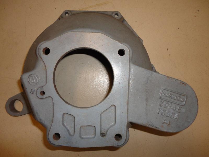
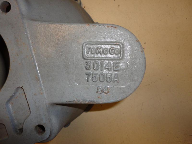
Hi All; I was wondering if anyone can identify a bell housing I picked up on eBay for a Seven project. I think it is from a Cortina Mk2 but not sure. The markings are 3014e with 7505A and about 6.5" deep. Problem I'm trying to figure out is what slave cylinder this bell uses. The hole measures 1.35"d and the standard slave I have (PAS 43) that I use for my Elans measures 1.1"d. This slave is supposed to be standard for Anglia, Cortina Mk1 and 2, and Elan bells. Any 105e Gurus out there? Thanks Allan
-
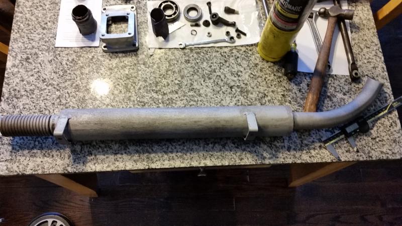
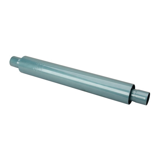
Hi all, I'm restoring a 1962 Lotus Super Seven with a Cosworth 1340cc motor and trying to find a suitable muffler/silencer to replace the original. I'm trying to keep the appearance as close to original as possible and will be using the original headers with 1.5" primaries and a collector outlet of 1-5/8". The muffler that came with the car measures out with 1.5" inlet and outlets, a 2.7" diameter body which is 19" long. Not sure if this is the original muffler, but it is marked G.N. Silencer. I was wondering if anyone else had gone down this road and found something suitable. I searched the forum and see that most threads are using more modern mufflers that have a much larger body and inlets and outlets. The closest match I have found so far was the Smithy's glasspacks which are 2" inlet/outlets, 3.5" body and are 22" long. Thanks Allan
-
Gearbox external assembly - I'm confused
Gearbox replied to Gearbox's topic in General Sevens Discussion
Thanks Dingo, I was going to do the same type of reinforcements in the engine bay and have it continue with 1" Sq. tubing running under both sides of the tunnel with a steel plate for the mount. Not real comfortable with the gearbox mount just riveted on the thin aluminum floor and tunnel sides. So I guess in my case, I would just bolt the rubber mount to the plate with an access hole in the middle to get at the single bolt to tie the gearbox to it. Simple, now all I have to do is figure out how high the mount has to sit and fabricate an aluminum block to elevated it to the correct height. BTW, I noticed that your frame is set up for LHD. Isn't the top diagonal tube from the scuttle to the front be on the other side? I have a RHD and the PO converted over and I'm in the process of going back the other way. Thanks for the info, Allan -
Gearbox external assembly - I'm confused
Gearbox replied to Gearbox's topic in General Sevens Discussion
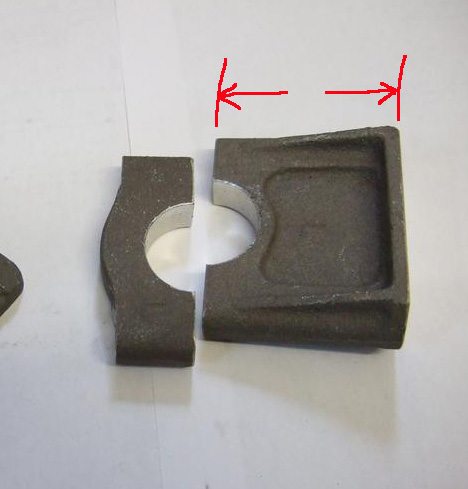
Thanks Dave, Can you post some pictures and dimensions of the correct bracket. I think I will have to start fabricating a part. Also, what part do I have? I was told it was for an early S2. I found the picture you are referring to, and yes, it looks different than mine. Looks like there is a "C" channel facing down that is flat on top welded between the two wedges, but not sure how the wedges are fabricated (bent) from the pictures. Any help would be greatly appreciated. Thanks Allan -
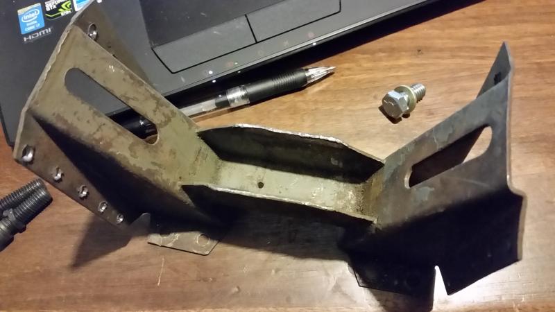
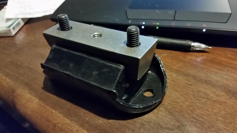
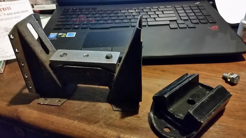
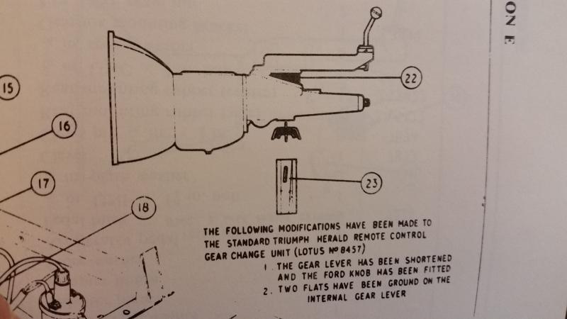
Happy new year all. I have been working in collecting parts to restore my gearbox and trying to piece all the newly obtained missing parts together before starting on rebuilding the gearbox itself. Trials and tribulations of building a car from boxes stored for the 40 years. First of all, I am working on putting together a 1962 Lotus Super Seven with a Cosy 1340cc Pre Crossflow and a 105e gearbox. Despite the PO saying it was a complete gearbox in good condition only missing the Triumph modified shifter, it was more than that. It was missing the gearbox cross mount bracket, gearbox mount, reverse gear shifter fork and rail, remote, and remote adapter. Between contacts in the UK and Dave Bean, I was able to assemble all of the missing bits........ I think. So first issue. I got a used gearbox bracket and was surprised to see that the only thing holding it was rivets to the aluminum floor and tunnel. Needless to say I will be fabricating a brace from the frame to hold it more securely. Dave Bean tells me that my 105e tail housing has a flat land to bolt the rubber mount onto, but they no longer make this mount. But they had an aluminum adapter that bolts onto the tail housing and then you could use a later rubber mount. OK, seems reasonable. But now with all the parts in front of me, I have no clue how it goes all together. The aluminum wedge bolts onto the tail housing, then the rubber mount bolts to the aluminum wedge. But how does the mount fit onto the gearbox cross bracket? There is no hole in the center of the bracket to tighten the rubber mount, nor does the mount fit on to the bracket. It almost seems that the aluminum wedge piece bolted on to the tail housing should just sit in the cross bracket without a rubber mount. But again, no place to bolt it down. What am I missing here? Do I have the parts upside down? Or maybe the wrong parts? Anybody have any ideas? Thanks Allan
-
Hi Dave; Understood, basically the reason why I am asking the question. I need a starting point and the difference between the Spit's/Elan's mount to what I believe was original to the Seven looks like more than an inch, and as you had stated, every 10 thousands will dramatically affect bump steer. But in setting up bump steer, I need something to fix the steering rack reliably in order to go through the bump steer measurements. From there I could either mill or shim the block to achieve bump steer, but need a hard point to do this so the rack isn't moving all over the place. A British car that is un equal from left to right? Impossible lol. Thanks Allan
-
I have an early S2 and am using a RHD Spitfire steering rack for the car. I was about to use the standard Spitfire rack mounts and noticed that the spacing between the mounts are too wide for my Seven frame. Upon further investigation it seems that the 62 S2 had a cast mount with no rubber bushing and a pin to hold the rack from rotating or sliding from side to side. I also see that the Seven mount is higher than the Spitfire system. I was thinking I could fabricate them from blocks of aluminum, but does anyone know the height of the centerline of the rack to the base? Or if these are available new or used? Thanks Allan
-
Looking for a set of shocks and springs for my 1962 Lotus Super seven. The will be pretty much stock, running on 13 x 3.5" steel rims and 155 tires, so not a race car. But I do want the car to handle well and not bend the frame should I hit a pothole. Something better than stock, but not full race if possible. I found that the QA1 Series 82 small body shocks are readily available here in the states using a 1.875" spring. I measured my stock Spax (I think) front shock and get a 12.5" extended and 8" compressed, and the rears measure 17.5" and 12.5" respectively. So the closest match I could find was the QA1 8243 fronts with a 13.75" to 9.38" and a 4" stroke, and the QA1 8262-4 rears with a 17.75" to 11.38" and a 6" stroke. Would these be the correct shocks for our cars? I understand that the rear top shock mount has to be modified from the stud to a eye bearing, so will that decrease the extended length? Or does it not matter? Also, since these will be height adjustable, what spring height and rates are everyone using these days, again for a street application running skinny tires. Thanks Allan
-
Hi Ian; Yes, I know Ted very well from his shop in NY. But I though he jobbed out all of his Pre and cross flow work and that was decades ago. I'll give him a call after the holidays, but not holding my breathe lol. I don't think these 1340cc engines was in anything racing related outside of the Sevens and most of that group swapped over to the 1500 back in the day. But you never know. Thanks Allan
-
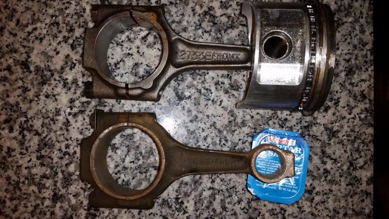
Part of my search included them, from Tony Ingram, Barry at PHP Racing, and Guy Smith from the UK. From what I had gathered, the 109e 1340cc engine was short lived, in the states it only appeared in the Capri Consul in 61 and 62 before going to the 1500cc motor. The Seven had it for less than a year between 61 and 62. And unfortunately none of the 105e rods nor the 116e rods (before and after) are even close. Even in the 105e 997cc configuration, the rods were considerably longer. So basically at a stand still with my rebuild. The only hope was to find a 2733e rod which I have 3, or another 109e rod which I also have 3 NOS. But the 109e rods had all been tossed for the reasons you mentioned and the 2733e rod, while slightly longer by 34 thousands and could be made to work, was in the early 1300 Cross flow motor which I do not believe was ever imported to the States. I did find a 1300 rod from Burton Power, but that only measured 4.14" which is 0.144" shorter and not sure if that would be too much. Pretty much trying to level a table and not having to remove all the legs to achieve a balance. So far I was able to find a set of 2730e rods which measures 4.37". My thinking was to fit the rods into the block and see how close I am to the deck. If the piston is recessed from the deck, I just mill the deck to zero. If the piston protrudes, then I am looking to make new pistons with a higher wrist pin location to compensate. Either that or re size the rods. No matter what, it isn't going to be easy. But where will be the fun in that? LOL.
-
Hi Steve; Yes contacted all the usual suspects on both sides of the pond and all said they were long gone. Even the 1300 crossflow stuff is pretty rare these days. The engine is a cosy 1340cc and puts out a whopping 85 hp, plus it will be a street car, so I think the 109e's would be ok, but I did find a set of 2730 rods from an early 1300 crossflow which are about 58 thousands longer. I have to do all the figures, but running a zero deck height with these rods may require new pistons, but what else can you do? The engine I have has a Moldex Steel crank, steel crank caps, and the billet rocker pedestals, so I think I will be ok. Just trying to keep the car as original as possible..... well at least on the outside , Thanks Allan
-
Hello all, I am searching for a 109e connecting rod, single or a set. Also would be able to use a 2733e rod, single or a set. Needless to say, I have 3 of each. Let me know what you have, Thanks Allan
-
Hi Wayne; I will email you, thanks for replying, Allan
-
Hi All, I am looking for the gearbox adaptor for my 1962 Lotus Super Seven. This is the wedge shaped aluminum piece that is sandwiched between the Spitfire Remote and the 105e/2000e tail housing. If you have one off the car but do not want to sell it, I would settle for dimensions off the adaptor in attempts in make one. Any help would be appreciated, Thanks Allan
-
Hi Geoff; I just dropped off the engine at my machinist and should find out shortly. But in the meanwhile, outside of the L,H, and GT was the 109e head the same in combustion chamber cc's as the 116e head? I believe I have a H head so will the cc's be the same as a 109e H head? I'm trying to determine if by using the 116e will it lower my CR substantially or not and how much can I cut the head to achieve the CR I want which would be about 9.5 or 10:1. Thanks Allan
-
Hi All, I have a bit of an obscure question that I cannot find anywhere. I'm building a 1340 109e with a 116e head. What was the standard combustion chamber volume in cc's and are they the same? Thanks Allan
-
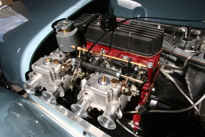
Cosworth Pre X Flow 1340 engine color
Gearbox replied to Gearbox's topic in General Sevens Discussion
Funny you should mention that, I was leaning towards that dark red/burgundy color with a black wrinkle valve cover and red Cosy logo. I think it looks very striking. Let me know what you find out, Thanks Allan -
Cosworth Pre X Flow 1340 engine color
Gearbox replied to Gearbox's topic in General Sevens Discussion
The best period picture I could find was an old ad for the Super Seven which looks like the Cosy valve cover was bare aluminum and the block was something else than black. Red maybe? Most Ford engines back in the early 60's were painted Black or Gray, so maybe Gray? Unfortunately the Black and white photo doesn't reveal much more and any color pictures I found were just of the outside of the car. Any original owners out there?
-
Cosworth Pre X Flow 1340 engine color
Gearbox replied to Gearbox's topic in General Sevens Discussion
Hi Dean; Unfortunately, that is not my car lol. But I do agree, that Red/Burgundy does look good with the wrinkle black Cosy cover. The gearbox on these cars were the 2000e like on my Elans, and they were always either Black or really Dark Green. I have several books on the Seven, and in no place it mentions the engine color, and of course every period photo of the engine is in Black and white, so no help there. I believe in 1962, Ford did not start using its trademark Blue yet, and I am thinking they were painted either black or gray. I am sure that Lotus would not have changed the stock color of these engines, but not sure if Cosworth painted them in a different color. Not sure what I am going to do yet, but it would be nice to know how these cars came from the factory. Thanks Allan -
Anyone know the original color(s) for a 1962 Cosworth engine? Was the head painted a different color than the block and how was the alloy valve cover painted? Wrinkle? Thanks Allan
-
Lotus Seven S2 Parking brake question
Gearbox replied to Gearbox's topic in General Sevens Discussion
Thanks for the useful info. I believe I have the standard 10 as all the parts were from the original car, but won't know until I get back home in November. At least I hope I do as the steel wheels I have are all 3.75" I believe (Triumph). Also, what makes a 1340 Cosy a Cosy? I've been trying to research this but have come up empty, outside of a A1 cam? Are the valves bigger? Is it ported and flowed? Just wondering. Finally, how much patina does you car have? Lets see some pictures. Thanks Allan