JakeC
-
Posts
33 -
Joined
-
Last visited
Content Type
Profiles
Forums
Store
Articles
Gallery
Events
Library
Everything posted by JakeC
-
Woohoo! That did it! Properly working turn signals. I think that is the last wiring fix on the car, and I think the last issue on the car all together. On to paperwork and inspection. Thank you all very much and especially @MV8 for your time and knowledge!
-
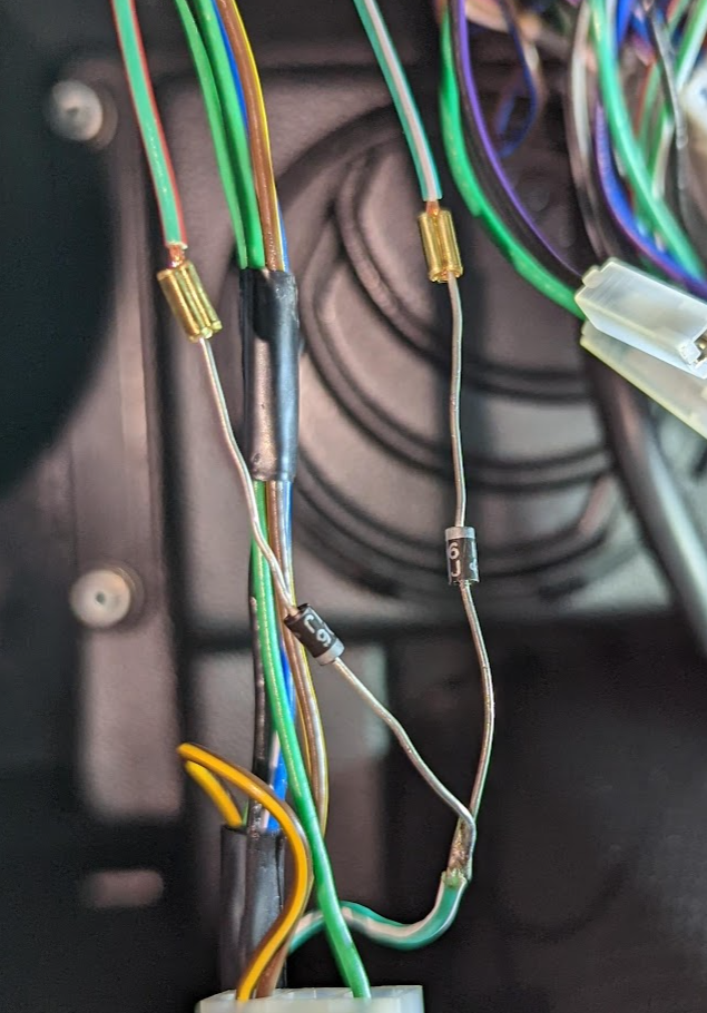
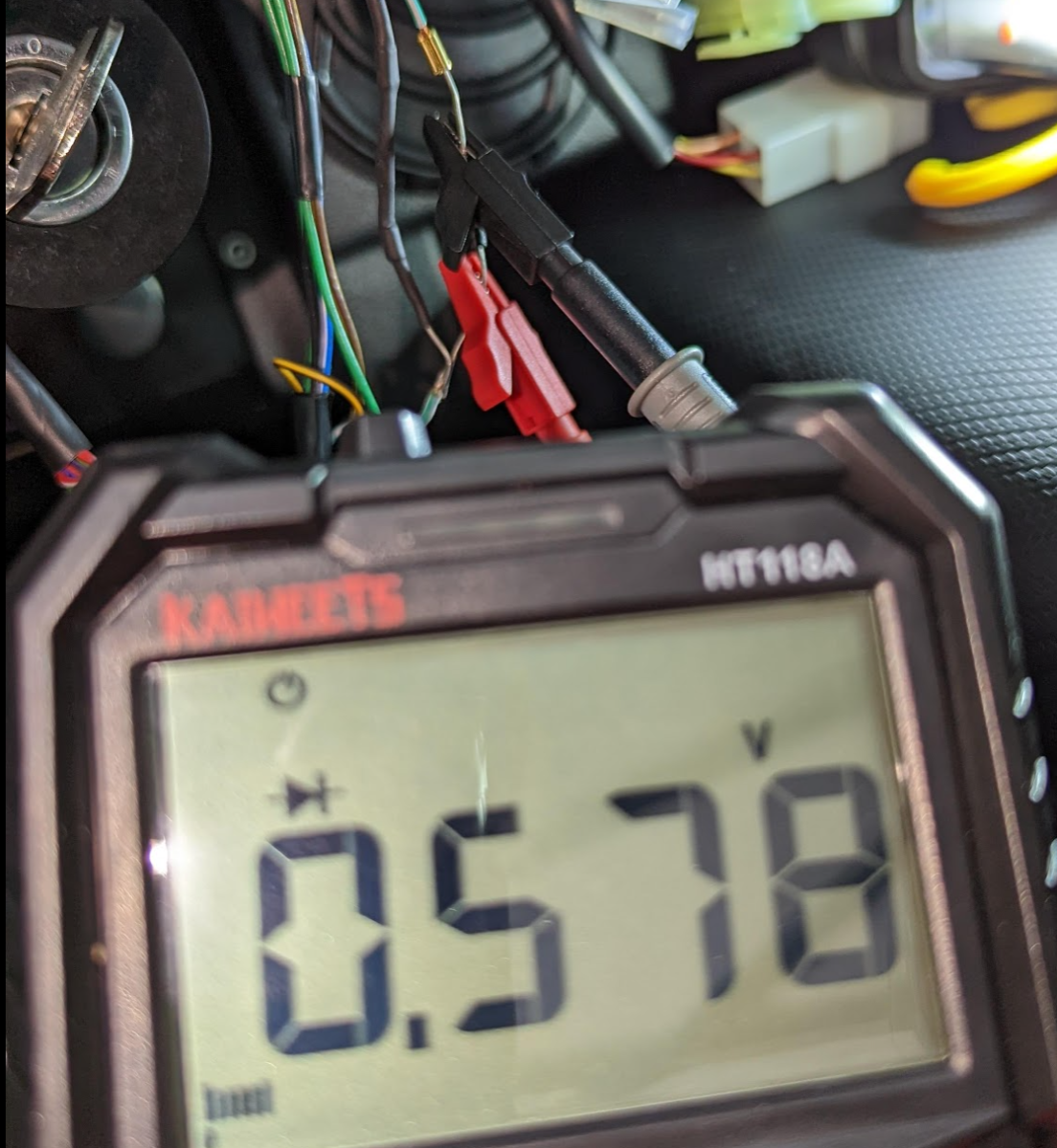
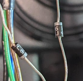
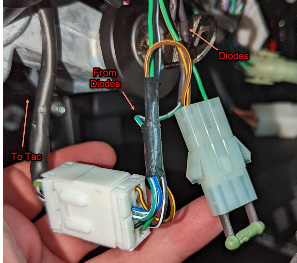
Allllrighty then. @MV8at first I tried what you suggested, and in continuity mode, I got nothing. Then I verified that I had continuity from the switch connector to before the diodes, and I do on both GW and GR. Next I stripped the heat shrink off of everything: You were right on with the connectors as being the second lump. I switched the meter to Diode test mode, and I get a forward voltage drop of 0.57'ish no matter which way I place the probes in terms of polarity. This is the same for both diodes. Note that I tested while the Diodes were connected to each other with the GW wire. I have not unsoldered them as of yet. Now I did notice that they are not "facing" the same direction: Wouldn't they need to be wired in the same direction? And if so, wouldn't that make the one on the right (GW wire) backwards? If that makes sense, I would be happy to try reversing it. Any chance anyone can confirm this logic? Thank you all and especially @MV8 for all of the time spent helping me out!

-
Had a hot minute to test continuity from the GW and GR switch plugs to the GW wire connector after the diodes, no continuity for either. Attached one probe to the switch white plastic female spade connector with the pair of GW wires and the other probe to the female connector pin where the GW wire goes in, set the multimeter to continuity, no beep. touched the two probe ends together just to make sure the MM was good, and got a beep. Not sure if I SHOULD have continuity there with the car off or not, but that is what I had time to test at lunch.
-
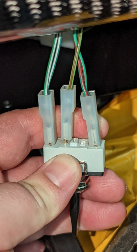
Thanks again @MV8. I used insulation piercing probes with the multimeter in the Diode check position. I also tried continuity and there didn't seem to be any. Now, I'm not sure if I hit the wires on both ends or not as it is tough to tell the difference between a failed open diode and a non-connection with the probe. I will try again. What I didn't think to try that you mentioned was just testing through the switch connector and the connector running to the tac. I presume it is a direct connection from one of the two wires in each pair to the tac, so I should be able to check continuity from the switch connector to before the diode, and then after the diode. I will try that next, and try to visually verify that the probes are getting to the wires, though it might be easier for me to strip the heat shrink off to actually see the wires. Will report back, thank again very much for your time!
-
Ok, so tried to test the diodes, and it looks like there are two of them on the GW and two of them on the GR wires. On on the multi meter it was OL for each wire no matter the polarity. What I didn't do was pull the diodes out and test them, I just punctured the wires on the way in and the GW wire on the way out. I think I am going to have to strip off the heat shrink and see if I can get directly to the leads to test them, and maybe have to cut them out to test. I also re-tried the switch wiring suggestion that Caterham had sent originally, GN on the outside and GR in the middle. The behavior was the same for the left side (all corners blinked) and no indicators on the right. Next I tried pulling out the GW wire from the connector that goes from the diodes to the tac: No change in the turn signal behavior, just the tac indicator did not light up this time, so I think the tac and tac wiring can be ruled out as the issue. Regarding the relays, the one with the tape is the flasher relay: Not sure which one is the hazard relay, but I also found this one under the dash: One last thing to note is that (with everything put back to stock) pushing the switch to the left blinks all four corners AND the tac indicator. Pushing the switch to the right, blinks the right side indicators, and NOT the tac indicator. I'm not sure when the tac indicator is supposed to flash. I think I might pull split the double wires on the switch side next, and see what happens.
-
@MV8 aaah crap, I copy and pasted the email images to the post. My bad! I will fix that up tonight. I am about to go out and test the diodes, and will report back. I can take pics of the relays as well. Thank you for the additional info, that makes a lot of sense, I will see if I can trace the wires as you described. Sounds like the tac doesn't make any decisions about what turns on or not, so I could try pulling those wires out of the ts switch to test. So I assume the indicator on the tac should flash with either turn signal correct, and not just hazards? Thanks again everyone for the help! Jake
-
Hi @sf4018, thank you! and yes I have looked at the 2015 wire diagram, unfortunately it does not have that connector on it. And that connector is fairly zip tied up with the wire bundle that goes down to the trans tunnel, so its fairly hard to get to. However I have not looked at the tac connector. It slipped my mind while I was under there. I will pull the rubber boot off and see if things line up. @horizenjoband @wemtd that is very interesting, thank you for the ideas! They are not LEDs but it could be possible that one of the diodes are faulty. I didn't really consider that, but I will see if i can check them. As a quick sanity check, is the double arrow light on the tac supposed to blink with the turn signals or not? Additionally, should it blink when the 4 ways are on? Thanks again to everyone for the suggestions!
-
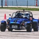
Hi all! Long time listener firs time caller here TLDR Version: Four way flasher button works as expected Pushing the indicator switch to the right works as expected Pushing the indicator switch to the left, flashes all four corners (no double arrow on the tac, flash switch does not light up) Swapping the GR and GW wires on the switch reverses the side that has the issue. unplugging a specific black connector allows the turn signals to work properly, although most of the rest of the dash then does not. Looking for a diagram or pics of the wiring of the connector. Long Version: I have just finished assembling my 420R, and as far as I can everything works with the exception of the turn signals. I have been trying to get support from my dealer and Caterham, but its tough getting anyone to respond or take the issue seriously, so I have been trying to work out the issue myself as it is preventing me from starting the process to getting the car titled and on the road. The issue is that pushing the indicator switch to the left side turns on all 4 indicators, pushing to the right, works as expected, right side indicators only. Swapping the GR and GW wires on the switch reverses the side with the issue. Left Side (not correct) Video: https://photos.app.goo.gl/tHKqnWB3kcGjiqT39 Right Side (Correct) Video: https://photos.app.goo.gl/m4JnVbMWbEcUoiwd6 I received 2 responses from my dealer before he had a family emergency (and I don't want to bug him anymore), and have not heard back from my attempts to contact Caterham directly. First they sent me a picture of the switch, but from all of my research, I think their switch is wired incorrectly. They sent: My switch looks like: Next the said "From the dash switch, this wire runs into the smaller of the two dash control module connectors (GR 14)." Then: "The wire then exits the dash control module through the larger of the two connectors (GR 99)." My wiring to the modules matches those diagrams: The last message was for me to verify that I did have the 420R subloom installed. and based on what they described, I do: S Gauges: R Gauges: Diodes on GR and GW: Connector: Soooo, that was the last I heard. I did some playing around and if I disconnect this one specific connector, the turn signals work as expected, however, most of the rest of the dash does not (as kind of expected) I cannot seem to find a diagram for that connector anywhere. So I would be eternally grateful if someone might share a picture of their working connector, or somehow has managed to get a hold of the pin out for it. Thank you so much, and if anyone has any diagnostic suggestions, or other ideas, I am all ears. Thanks again! Jake