Mudder
-
Posts
56 -
Joined
-
Last visited
Content Type
Profiles
Forums
Store
Articles
Gallery
Events
Library
Everything posted by Mudder
-
Welcome!! Don't purchase hoses, yet. What cooling system does your original build have? If it's the original "partial loss" system (no pressurized expansion tank) consider rebuilding the system!! IamScotticus is a walking encyclopedia on many things Kent engined Sevens and he pretty much coached me through rebuilding my cooling system. I am driving my 1999, 1700 Super Sprint very spirited over High Elevation Passes in Colorado or stop and go traffic in Denver and it has NEVER missed a beat. The cooling system, Thanks to Scott, has been extremely reliable. If you want to go that route, very few of the original hoses will work. Also the stuff Caterham offers on its website might be slightly different than what you have on your car. It will be a waste of money if you plan on a cooling system modification. No worries, it's not a major project, but most definitely worth your while. What shape is your engine in? Cheers
-
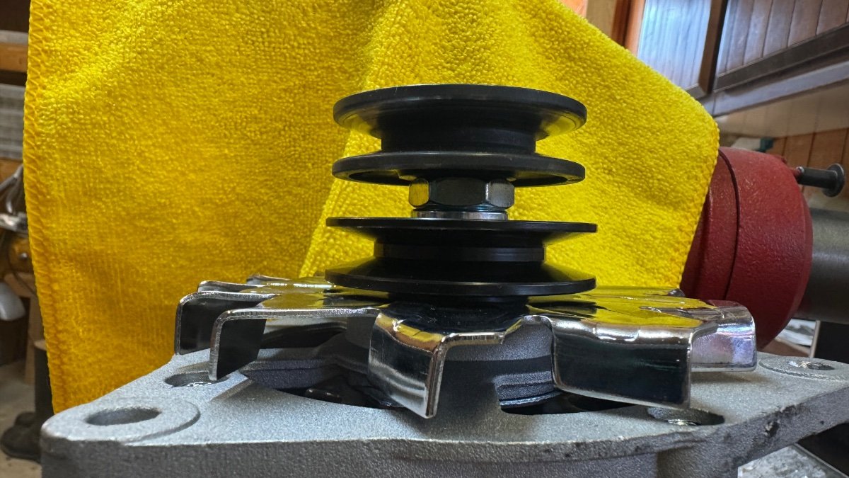
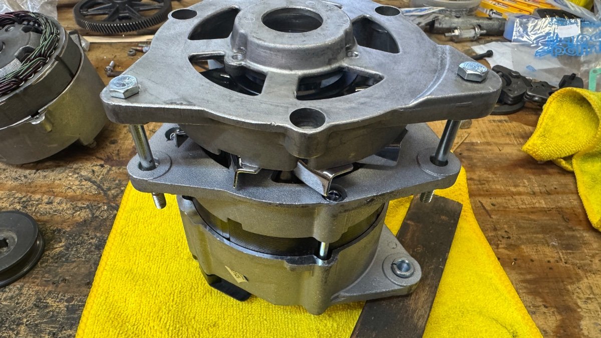
Okay! the first measurements are taken. NSXguys Amazon recommendation might be the ticket, in deed. My Magneton seems to be unoptainium. There is only one supplier in the US and they don’t order spares anymore. The size matches my old “original” alternator and the clocking is as close to perfect as it gets. Even the bracket fits. It might just be a dream which rarely happens in my Brit car experience, but so far so good. I’ll install the Amazonia Version next week and report back. And I am in the process of rebuilding the original. Many Thanks to NSXguy and all the others who helped to get the current flowing again.

-
I'll provide the measurements as soon as I am back in CO.
-
No worries I am always trying to safe everything original!
-
I will. Thanks for posting!
-
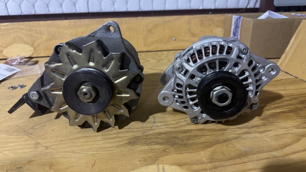
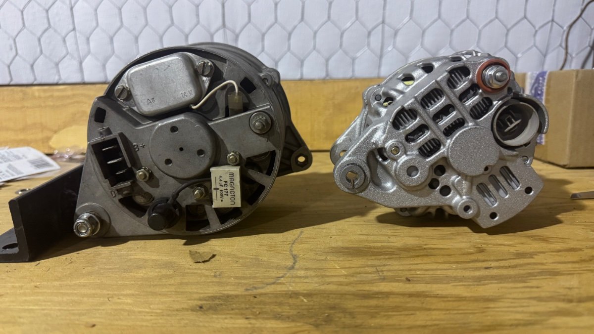
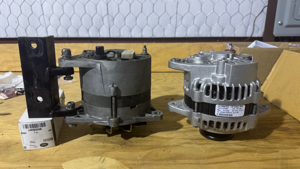
Here are a couple of shots which show the size difference. in comparison the “original” alternator (left)which probably was a mid 2000s replacement, because Caterham supposedly used Magneton Alternators during this time frame demands a blood/skin sacrifice where as the Geo Metro (1996) one leaves the mechanic’s hands somewhat intact. see for yourself the clocking of the new alternator will need some bracketeering!
-
Nice Fabrication!!!! As soon as I find some time I'll send pictures of the brackets installed without the "Boat Anchor"
-
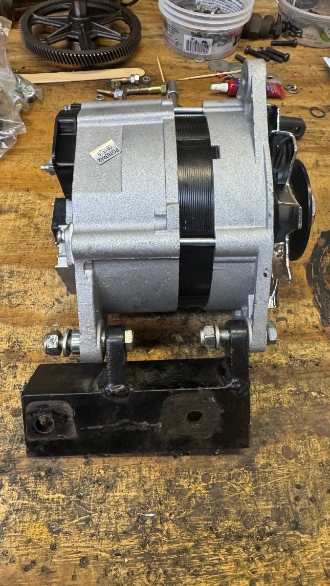
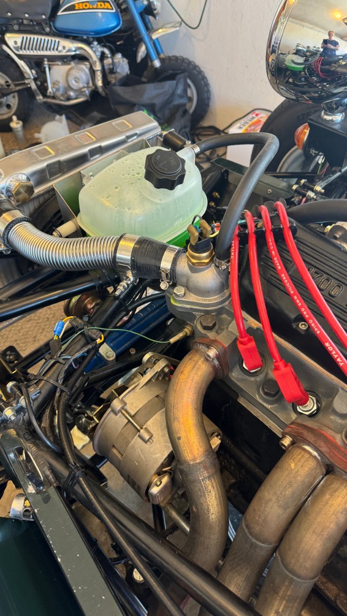
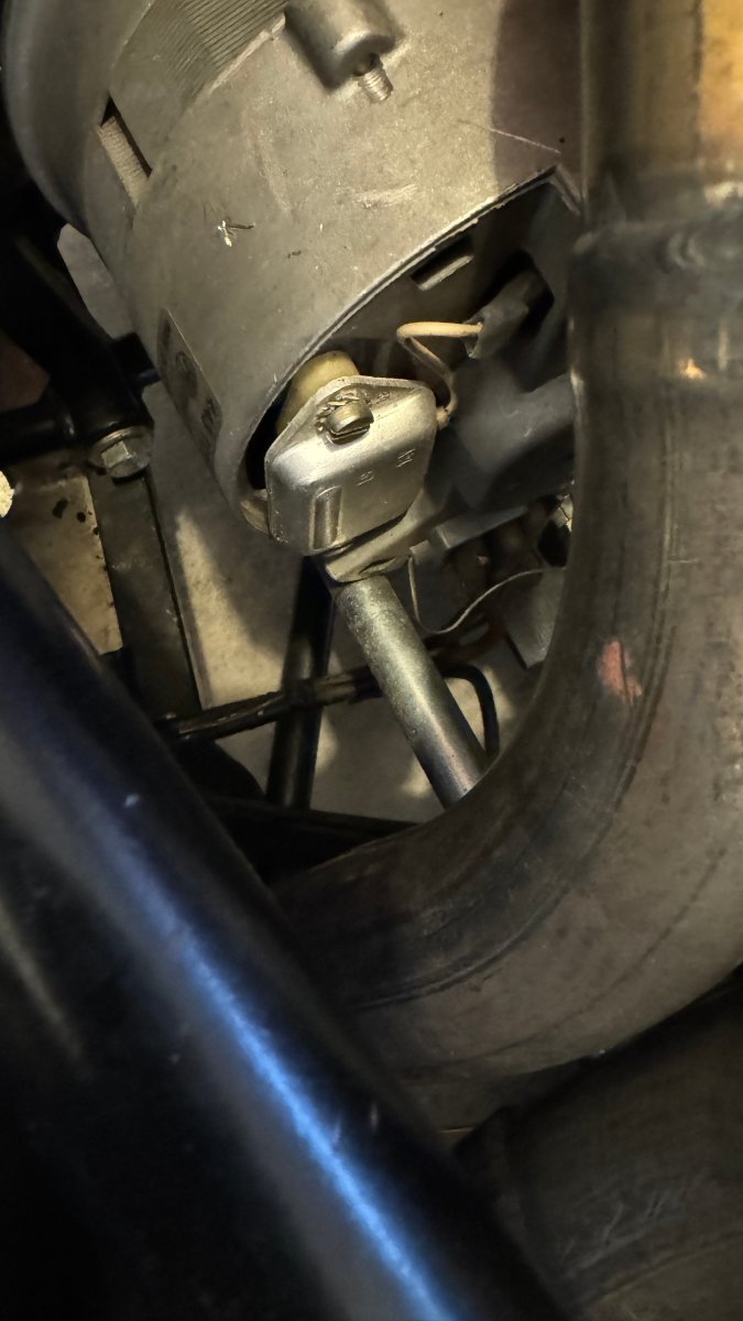
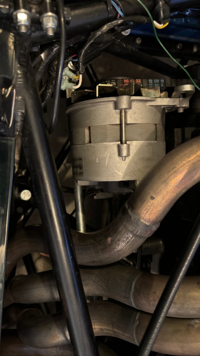
MV8 hit the nail on its head. There is NO space. I pulled the alternator today and it barely (as in nearly not) cleared the exhaust/frame/ steering column. The Geo Metro alternator got delivered and it seems somewhat smaller but needs bracket fabrication. My suspicion was correct. The front bearing on my Magneton Alternator is shot. That's were the ringedinging was coming from. I will try to get the bearings changed for right now. The bracket fabrication will be next (winter project). Thanks for all the help so far.
-
MV8 Thank you very much. Great advice. Working on it!!
-
That made me smile! thanks for sharing!!
-
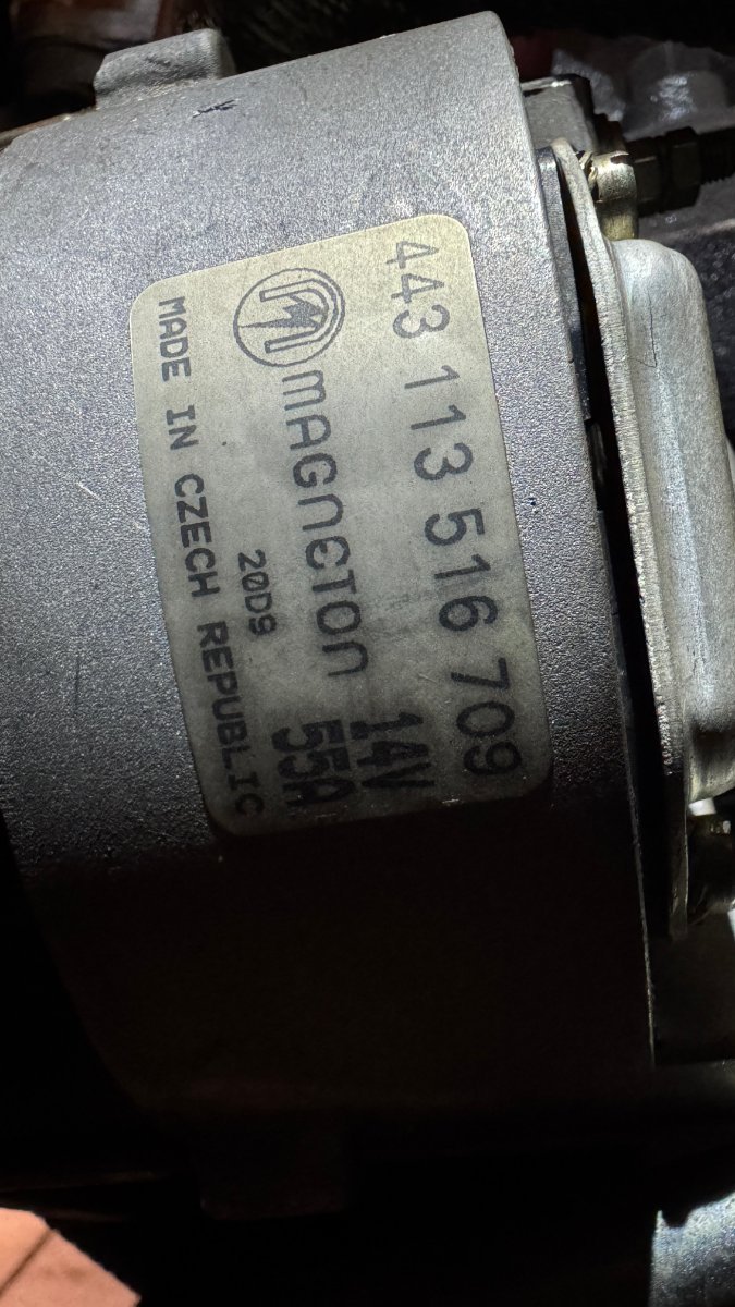
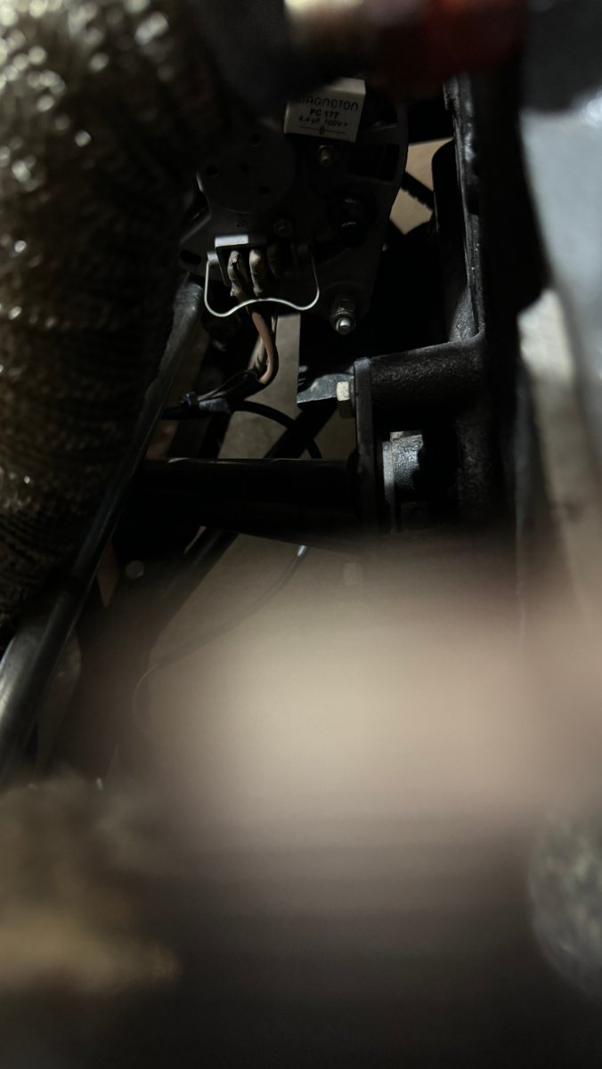
Dear Seveners, I think one of my alternator bearings is going south. The alternator is still working, but the tiny bell like sound (ringeding) it produces drives me nuts. The sound could come from somewhere completely different, but I am getting tired of this Wild Goose chase, so I decided that I will start with the alternator. I would like to replace the unit with something I can easily get off the shelf. Reliability and availability are my main objectives. My Seven is a stock 1999 S3 1700 Super Sprint (LHD). Four in one stock exhaust. The real estate for the alternator is very limited and I am not sure whether it is the original unit (see attached picture) All the attachment points look very much stock. There is an angle iron attached to the bottom of my engine block, which serves as the mount for the two alternator bolts on the bottom and there is the usual adjuster at the top which mounts to the front of the engine. The electrical connections are three spade connectors which seem to have the cover/housing missing. The Alternator is a MAGNETON 14V 55A unit made in the Czech Republic. Part number is 443 113 516 709 Additional code on the sticker: 20D9 (could be a date code) I searched the Googles for a couple of hours, but cannot come up with a matching unit. I contacted MAGNETON, but haven't heard back If any of you has one of these units (working) for sale I would be happy to purchase it. Preferred option is however to come up with a "better" solution. Thank You!!
-
Thank you so much to everybody who chimed in. Still trying to find a cost effective AFR logger. The Innovates are kind of up there. well, it will be a worthwhile investment.
-
Removed!
-
I temporarily plumped a fuel pressure tester right after the fuel pump and my mechanical out put is 3 psi, revving it to 2000-4000 RPM With the Holley regulator in line my pressures are bouncing between 2 and 3 psi in the same Rev. range The regulator is a Holley 12-804 . It's difficult to get ethanol free gas around here. 91Octane comes as E10. I am at high altitude (8000ft) and I will try to jet it down a bit. Thanks!!
-
I talked to Innovate and they couldn't tell me where to install the AFR sensor on my 4/1 no cat setup. The Tech Guy was worried about wrong readings. I'll try Performance Electronics next.
-
Well, 1. revving the warm engine at idle creates black puffs out of the exhaust 2. gas mileage went down to about 15mpg from 20 mpg 3. very black spark plugs 4. fuel droplets on my right clamshell Funny enough it runs fairly well, no real flat spots. 2-3000 rpm, putzing through 30 mph zones it becomes a little erratic. I pulled the floats (plastic, about 19grams each) and reset the height to 13mm and travel to 25mm (measured in the middle of the flat side) I was surprised to see some marring on the needles (1.75, 3000 miles) I synchronized the carbs a couple of days ago and my idle screws are about 2-2.5 turns out. New needle valves (1.75) are on order. Pierce Manifolds recommended a 60 F8 idle jet and I will install a Malossi Fuel pump and regulator. The Holley regulator I installed 2 years ago is inconsistent (measured by my fuel pressure tester) Carb Setup: 40 DCOE 151 (Spanish), new from Pierce Manifolds: Mechanical Fuel pump (very consistent 3 psi out put) Choke 32mm Idle Jet 50 F9 Emulsion T. F11 Main Jet 120 Pump Jet .45 Needle Valve 1.75 Air Corr. 170 Cheers
-
Dear Seveners, I've been tinkering with my 40DCOE's for quite a while and I think I am getting quite good at it. However I would like to get a little more analytical in regard to AFRs. I am running a stock 1700 Super Sprint. My compressions are excellent and the engine is timed properly. I optimized my 123 Ignition on a rolling road and both of my DCOE's are new (40 DCOE 151). The engine pulls pretty well, but at my elevation of 8000 ft, I would like to tweak the carbs based on proper AFRs. Does anybody in our group have experience with installing an AFR sensor in a classic dual Weber, 4 in 1, no cat setup. Essentially I am running four small 425cc engines which can all be tweaked individually ;-). A single sensor wouldn't really work IMO. Please fire away! Cheers Wolfgang
-
I picked up a Caterham - does anybody know its history?
Mudder replied to masanski's topic in General Sevens Discussion
Congratulations! Nice find. The "Twin Cam" looks awesome. I own a 1999 S3 " Life Axle", 1700 Super Sprint. The original owner's son, sadly his Dad had passed, couldn't provide much info. However, Martin Phipps (Martin.Phipps@caterham.com) , the Caterham Archivist, was able to provide all the detail I could have ever asked for. He might not be able to shine any light on your engine installation, but he would know pretty much everything else. Original order, spec sheet, where the car was delivered to, etc. etc. I hope this helps. Cheers Wolfgang
-
MV8, Thanks for all your great advice. I need to find a shop which can do some custom work on the ex-manifold. I’ll check with Josh.
-
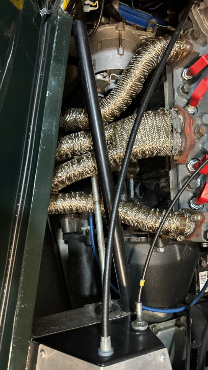
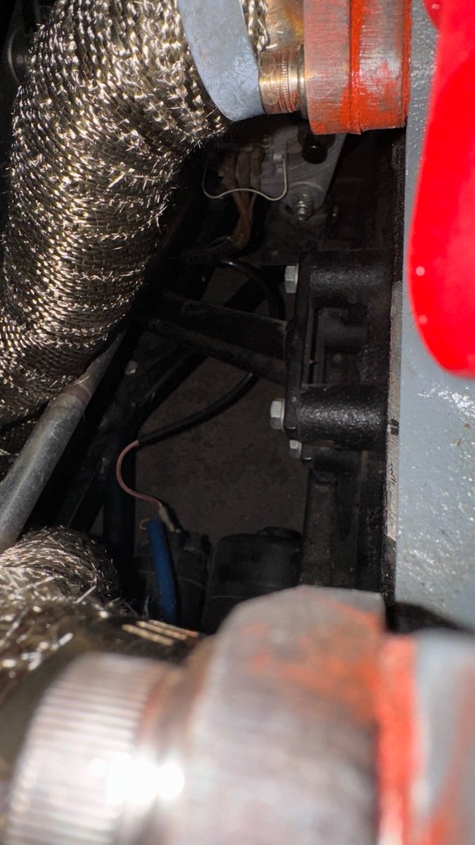
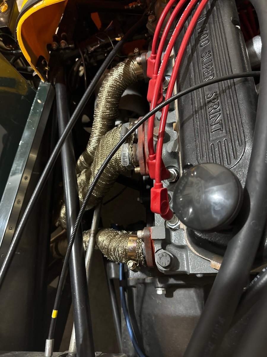
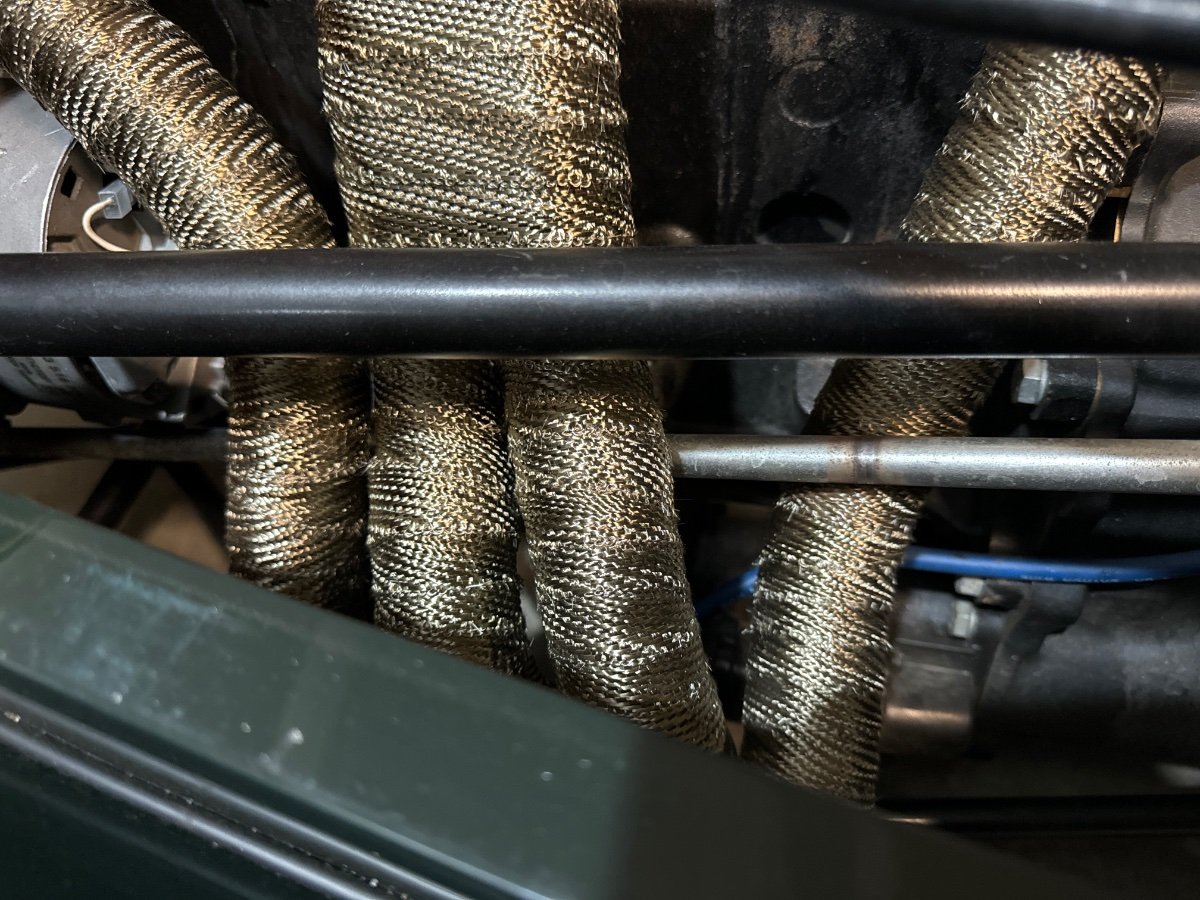
My setup is completely different. see attached pictures. The real trouble makers are no3 and no4 down pipes, but no2 could ply a role, too. Very annoying! I hate to rig things, but….
-
Most probably. It took a little coaxing on the new ones.
-
MV8, Thanks for your input and kind offer. I am a little bit between a rock and a hard place here. Any which way I move things, there will be interference. The steering column has about .5mm wiggle room. I showed it to Josh Robbin’s the other day and even he scratched his head. IMO there are 3 options. 1. Build new headers. That’s my least favorite. 2. “Malletize” the pipes in the problem area. 3. Design a new lower steering column. Retain the attachment points but go slightly smaller diameter with tubing instead of solid stock. Please let me know your thoughts.
-
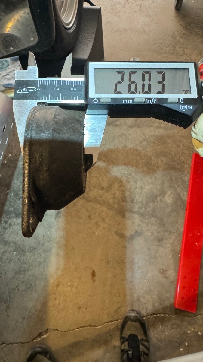
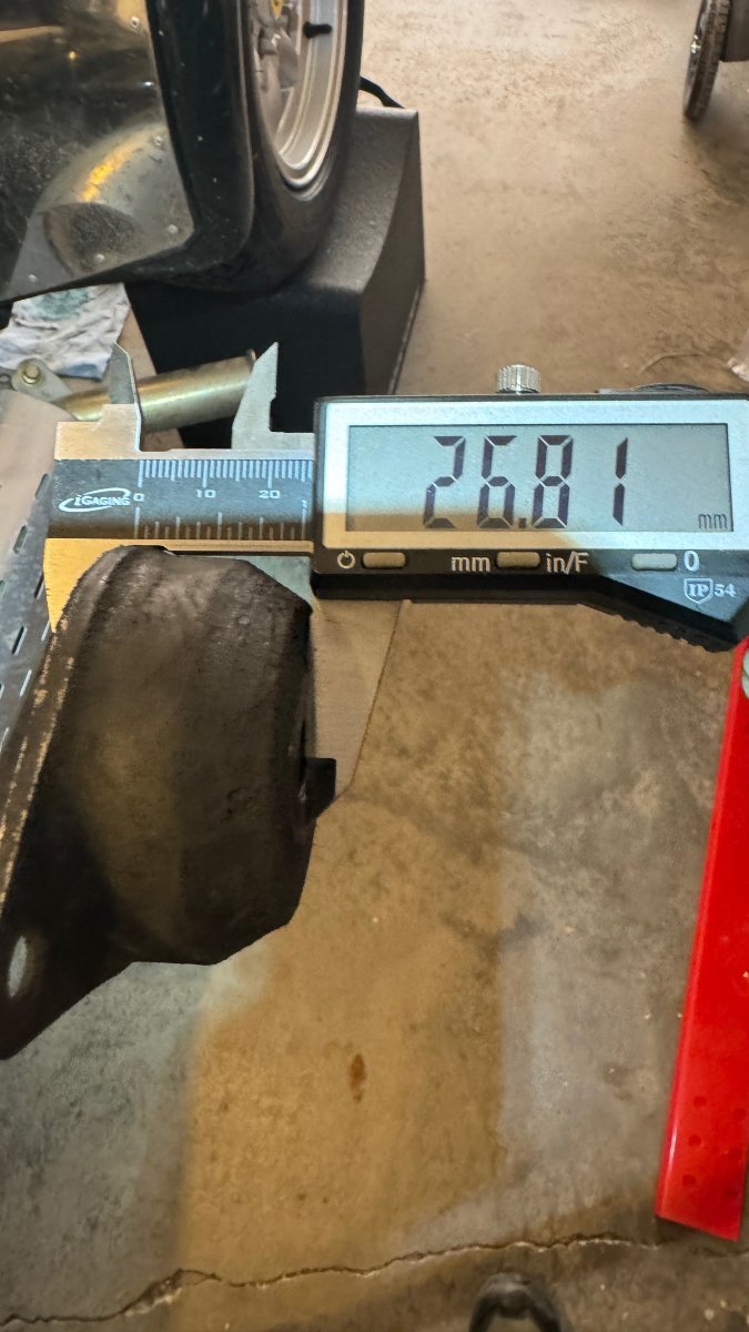
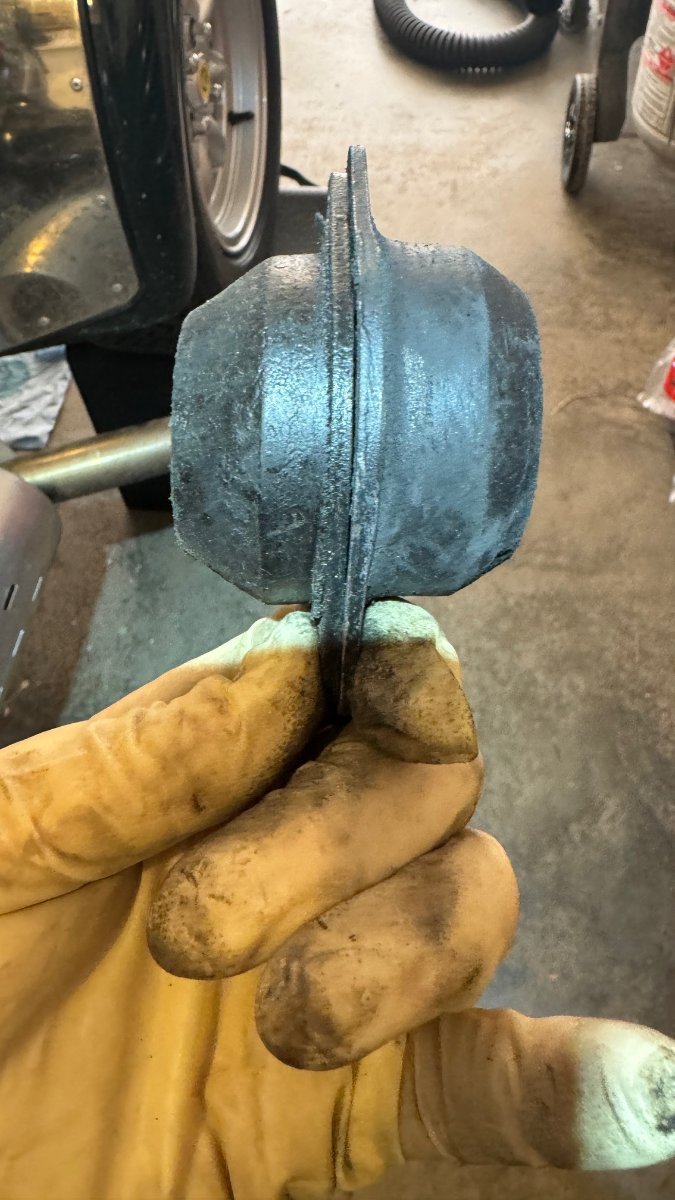
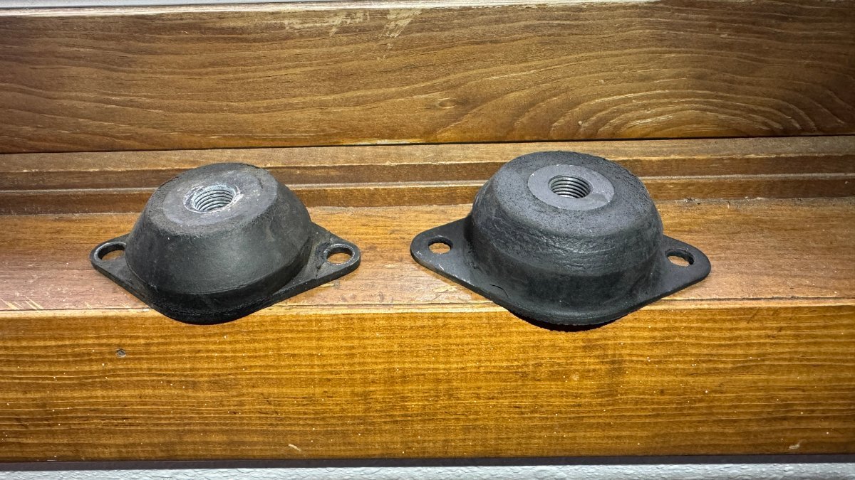
New Engine mounts are in. It took a little wiggling. I loosened all main bolts (3) including the transmission (T9) and jacked the engine up slightly. The new rubber mounts slid right in. The tranny mount hasn't arrived yet. The new mounts appear to be a little beefier. Then on the other side, the 25 year old ones might have settled a bit. (the new one is the one on the right)
-
New rubber mounts are ordered for tranny and motor. I'll report back.
-
Great idea! Thank you.