EdWills
-
Posts
237 -
Joined
4 Followers


-
Not sure if many Seven/7 owners in Canada purchase from the U.K., but I've recently received a few orders from shops from over the 'pond' via Royal Mail, and the service has been fast and I've been kept informed of the routing every step of the way. Not sure if this is new, but I don't have to sign in to the Royal Mail website, they just send me email updates as the shipment progresses? Also, postage and insurance rates seem very reasonable - at least from some suppliers, plus Canada Post has also been very fast with these same deliveries when they arrive here. Found a couple of quotes on-line, one from Jeremy Clarkson: 'Colin Chapman summed up his philosophy thus: "Simplify and add lightness". Mind you he also said "You would never catch me driving a racing car that I have built". 'Which probably explains why Lotus came to be known as an acronym for Lots Of Trouble, Usually Serious'. "Have you ever noticed that anybody driving slower than you is an idiot, and anyone driving faster is a maniac?" George Carlin. Happy New Year. W.
-
- 3
-

-

-

-
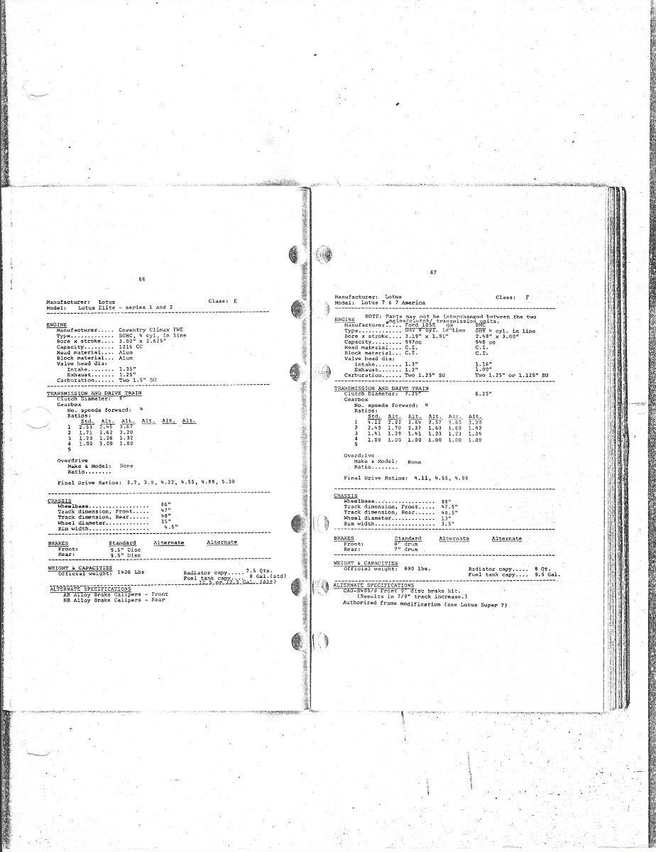
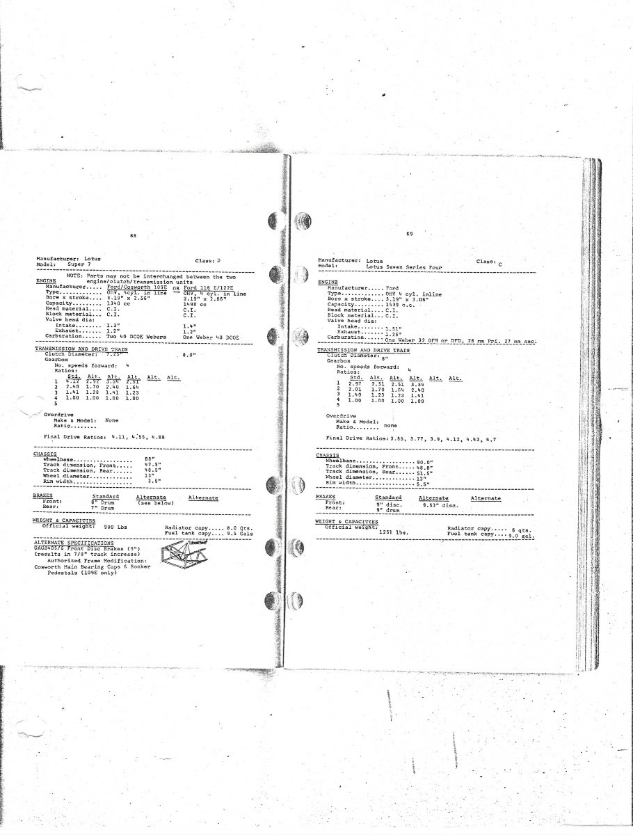
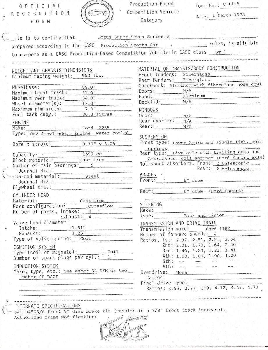
Hi Tim. I found these pages in my notes from when I purchased my car. The second owner had raced the car in Canada. The first 2 pages were from a 'black book' but not sure if it was SCCA or CASC (Canadian Automobile Sports Clubs 1958 - 1988). I have also included a page from the CASC dated 1978, which specifically details the Series 3, however you may note the error of the person/body/organizer who typed in the note that the front brakes specified for the 'Lotus Super Seven Series 3' were '8" drum' with a disc brake conversion as an option.. As front drums had not been used on a Lotus Seven for quite a number of years (and never were used on the Series 3), one can only conclude that they took the info from a very old spec. regarding the Series 1 or early Series 2 cars? Also, not sure if they 'borrowed' the specs from the SCCA? Forum members who race(d) in the older SCCA series may know if the smaller pages are in fact SCCA or possibly CASC specifications? Will. And a P.S. Tim. I hope you won't require a magnifying glass to read the specifications? They are from a very old photocopy from the early 1970s.

-
Looking for bellhousing for twincam/crossflow
EdWills replied to Healeyracer's topic in General Sevens Discussion
Hello Henry. Thank you for all the info. I noted that the same Elan forum also contained a comparison between the 105E and 113E bellhousing ('Difference between 105E and 113E bellhousing') which also shows the factory machined clearance in a 105E unit. As @MV8 advised, it would be a good idea to check the clearances just for peace of mind. On another note, I just received an ad from 'Absolute Lotus' magazine. Although I don't subscribe, I purchased some back editions and they placed me on their list. In the 2026 edition, there is a story of a 90 year old Lotus Elan driver who still competes in hillclimbs (but thinking of hanging up his overalls?). Oh to be young again! Also sad to hear about Chris Rea noted in another post on this forum. Merry Christmas to all, and a Safe and Prosperous New Year. Cheers. W. -
Looking for bellhousing for twincam/crossflow
EdWills replied to Healeyracer's topic in General Sevens Discussion
Hello Henry. I still can't find the article on the Twin Cam bellhousing, but I did find some interesting perspectives on which type is suggested for use on https://forums.lotuselan.net Two contributors, '2cams70' and 'promotor' (under the heading '4 speed bellhousing') provide details on the Ford bellhousing part numbers. '2cams70' advised that some 105E bellhousings he had seen were professionally machined internally (by Ford?) for clearance for the slightly larger twin cam flywheel and clutch. The bellhousing was apparently given a different part number by Ford (not necessarily a different casting number?) due to the machining process. W. -
Looking for bellhousing for twincam/crossflow
EdWills replied to Healeyracer's topic in General Sevens Discussion
Just to confirm what Henry @SENC has noted, the Twin Cam flywheel and clutch may fit in the 105E bell-housing, but an article that I am still searching for, advised that it may be a tight fit, and there may be clearance problems inside the bell-housing. The Twin Cam clutch was an 8 inch diameter unit, but Burton Power advise that the flywheels they sell for the Twin Cam and BDA are for an 8-1/2" diameter clutch? David Vizard in one of his books on the Escort advises that if you wish to upgrade to a Twin Cam in one of these cars, then the appropriate clutch, flywheel and bell-housing are required. He provides the original Ford part numbers for his suggestion, but I do not know if they are still current? As @7Westfield advised, Burton will sell you an alloy bell-housing that is noted to accept the clutch and flywheel for the Pinto, Twin Cam and Crossflow (7.5 inch diameter clutch.), but not cheap. W. -
Lotus Seven Frame and Chassis Numbers
EdWills replied to EdWills's topic in General Sevens Discussion
Hello Henry. I contacted my pal who updates the web site, and he will add a postscript to my article that provides information on J.W.s site in the U.K. Thanks for suggesting it. Cheers, W. -
Lotus Seven Frame and Chassis Numbers
EdWills replied to EdWills's topic in General Sevens Discussion
Hello Henry and forum members above. Many thanks for the compliment. John Watson provided a lot of information to me for the article, I didn't want to duplicate (copy) other information he has previously provided on his web site, so I noted his site in the reference section. On reflection, I should have mentioned where to find this info! John's 'Lotus Seven Register' has a couple of photos that show the possible location(s) where the frame identification is stamped by the frame contractor. They are shown by clicking the 'register page' and scrolling down. J.W. does advise that the frame identifier letter/number can be in various locations depending on when the frame was constructed, but there is no mention if Lotus (or the frame builder) ever recorded exactly where they would be located. Lotus fitters similarly seem to have riveted the Lotus plate in different orientations to fit around the heater for example, but in all of the photos I have seen, on the flat horizontal aluminium sheet in front of the scuttle. Which side of the flat panel would depend on whether it was a l.h.d. or r.h.d. car. It does appear that the 1" angled steel bracket - that holds the front of the brake and clutch master cylinders alloy bracket - was the location used by Universal Radiators, but J.W. also shows another location on older cars produced by Progress Chassis. I am guessing, and this is only my guess, that the angled bracket would be easier to stamp before being welded on to the frame. Similarly, the plate that John refers to as being welded on to the frames constructed by Progress, would be pre-stamped. It really wouldn't matter what order the frames came off the production line, as the mis-match in frame builder letter/number combinations to the Lotus chassis number combinations reveal. Some may be very close to each other, some hundreds of numbers apart. I have only found one Lotus Seven so far that had the exact same builders i.d. number to the number on the Lotus plate. And just to throw another bit of confusion into the mix, John advised me that the last Lotus Seven Series 3s to be produced were SB2649 a, b, and c. I queried this, but it seems that as Lotus was at the end of the Series 3 line, someone at Lotus involved with the Series 4, decided (insisted?) that the Series 4 (or IV) should start with the chassis number of '2650'. With three Series 3 chassis waiting for completion, they were given the numbers SB2649a, SB2649b, and SB2649c. Not sure how this was viewed by the U.K. vehicle licensing office, but it must have been accepted, as they are fully recorded as individual cars in the Lotus factory records that J.W. has, and were registered for the road. W. -
For Lotus Seven owners or prospective purchasers of a Lotus Seven, I have added a section "Lotus Seven Frame and Chassis Numbers" on https://anglocanadianlotus7.ca dealing with frame and chassis numbers, plus the estimated numbers of cars built. The article was written with the help of John Watson of the Lotus Seven Register, plus a few recommended books. John Watson has detailed on his Lotus Seven Registry the locations on the Lotus Seven frame where the frame constructor stamped their build number, before bodywork was added by another company, with Lotus then riveting their aluminium chassis plate with their serial number on to the flat scuttle area. Hope it is of assistance. W
-
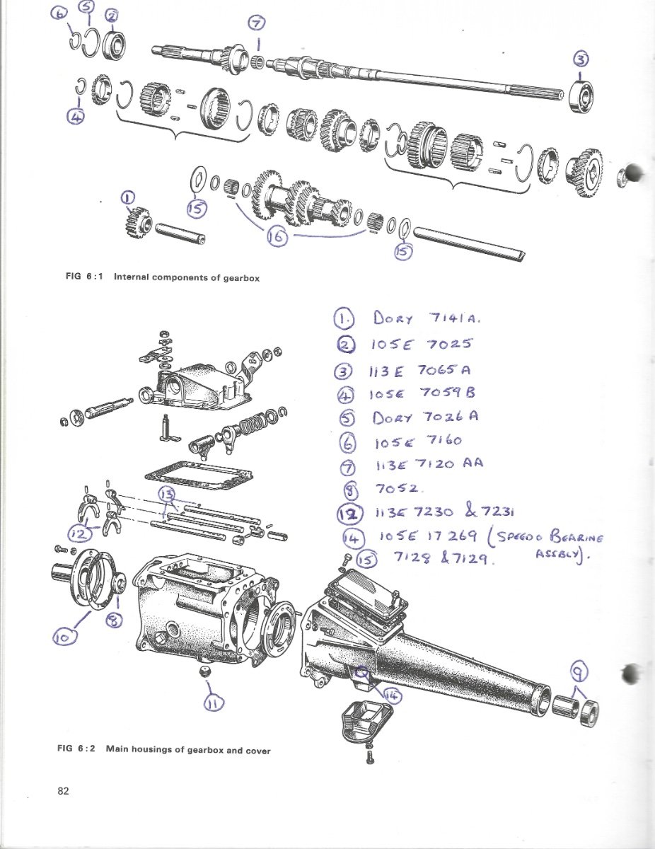
Just rechecked the Burton Power web site, and the 2025/26 catalogue is free with free delivery world-wide (Just ordered one. I have no connection to this company, but have sourced many parts from them in the past). A download version of the catalogue is available at https://burtonpower.com and on pages 114 and 115 there are colour photos of each Ford transmission with parts list and details of each. W
-
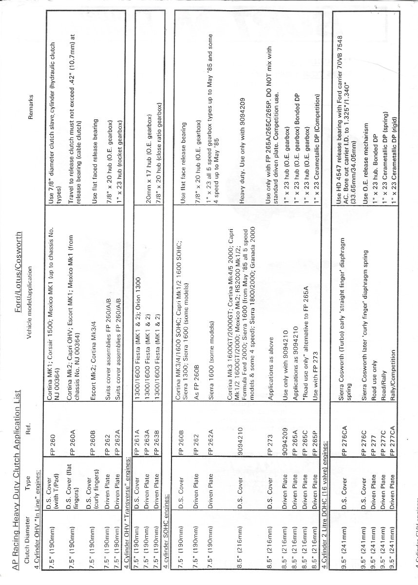
Hi CHristopher. According to author Paul Davies who wrote a book for Cars and Car Conversions titled "Tuning Four Cylinder Fords" (published 1971), quote: 'First all-syncro box was that fitted to the 1200cc Anglia Super and the 1200 Mk 1 Cortina. Apart from the advantage of having a syncro first, this unit should be regarded in the same light as the 105E/109E boxes (my note - no syncro on first on these earlier boxes) having ratios unsuitable for spirited motoring. In this same form this box was also used in the 1500 Cortina, Classic and Corsair models, and - initially - in the GT versions with the addition of a remote change" (remote change part 113E). He also notes: "Ford Performance Centre (as it was then) marketed a special kit which provided uprated 1st, 2nd and 3rd cogs for the 1500 GT casings." These were later incorporated into the 'new' (for 1967) box known 'incorrectly' (Mr. Davies' words) as the 2000E box (actual 2821E). The 2821E was later fitment into some 1969 manufactured Lotus Seven Series 3 models as supplies of the 116E dried up, plus the Seven Series 4 and Elan. The Lotus Cortina Mk 1 received an ultra close ratio box which Mr. Davies noted proved a little unsuitable for everyday use. In the Lotus Seven Owners Manual, Lotus refers to the 116E as an engine and gearbox combination. Christopher, I mentioned to you once before about Burton Performance in the U.K. I realize with the ongoing tariff situation that importing from the U.K. has become overly expensive, but Burton does have good reference material for clutch and gearbox combinations. The 1 inch 23 spline you note was used with the 'Type E' Rocket Box' (single rail operation - as used on the European Ford Taunus and others?). The original equipment gearboxes used the 7/8" x 20 hub according to Burton. I will attach a page from their old print-out regarding AP clutches (these original AP clutches may not be available now, but replacements are), which may help decipher the combinations. If you think it will be useful, a copy of the latest Burton catalogue may be very helpful to you, or just check on-line https://burtonpower.com Only cost for the catalogue will be postage (no tariff charge). It details the full range of gearboxes produced for the U.K. and European markets with all the necessary accessories noted. I have also added a page from the Autopress Ltd Ford Cortina 1967/68 manual where I noted the parts required for my 116E box rebuild as fitted to my 1969 reg. (built in 1968) Series 3. I am guessing that these parts have been unavailable for some time?. Cheers, W.
-
Maybe check with your health professional?
-
A GPS tracker is a great idea for expensive equipment such as a trailer. A neighbour of mine around the block, had his utility trailer stolen from his front driveway during the night. The thief had to drag it out onto the street backwards in order to attach it to the get-away vehicle. Unfortunately, no one heard the probable racket, even the owner. He was able to track the trailer to a trailer storage yard, and the yard owner found it hidden in the back of the lot. An employee of the yard was charged with the theft. Presumably the thief hoped to store it for a while, with no one at the yard noticing, and then sell it on. W
-
Hi Scott. Most of the LHD and RHD Series 3 cars that I have seen were fitted by Lotus with the amber Lucas L691 signal lights mounted on a bracket fitted directly under the headlamps (as per mine and other Series 3 Sevens that were imported into the city where I live). Lotus attached the amber signal lamps to the side of the nose cone on the 13 or so Twin-Cam cars (all RHD except 1), and possibly some owners chose to do the same? Photos on https://simplesevens.org will show how Series 1, 2 and 3 cars are equipped. Also Tony Weale has a number of photos of how the lamps were mounted. (see page 111 for example of a Series 3 RHD). My scuttle came from Arch after the Caterham take-over (I have no photos of my original unit unfortunately), so possibly Arch may have followed suggested aircraft practice and placed the pop rivets at the recommended spacing (roughly 1 inch apart for a 5/32 inch rivet @MV8?). I don't think that Lotus were practising 'add lightness' by only providing 23,24, or 25 rivets on Timothy's or your scuttle Scott, but maybe cutting costs because, as noted, the scuttle is not structural? Also, if an owner wishes to keep the firewall and scuttle in one piece, it does make it stronger to handle to remove and replace and it keeps its shape better this way to avoid having it buckle. Only the hole above where the steering column slot is located needs to be modified to join the two up. (see: 'where can I get a Series 2 nose cone by @Bill. His scuttle appears to have the modification I am referring to). In any event, to remove the scuttle without a firewall attached, you still have to unbolt it from the frame, and remove the wiper mechanisms. With a scuttle that is kept intact, the choke cable also comes off with the scuttle, after unbolting the end from the carb(s). So naturally, whatever works best for you. Cheers, W. Just a P.S. Just read an article from the 1980s by a Lotus Seven racer in the U.S. He described the twisting that an original (unmodified) Lotus Seven Series 2 frame goes through in a race situation, and the stresses placed on the frame, ally body, and rivets. I would have to defer to @MV8 to advise if Arch - with my scuttle at least - were trying to make this body part more structural? With double the amount of rivets than required by Lotus, double bolt and nut fixing on each side of the chassis, and a strong channel piece to cover the area of the scuttle that bolts to the frame, possibly Arch have attempted to provide some structural support to the top of the chassis. I wonder though, how much extra it would provide? W.
-
Hi Timothy. I think I see what you have done. My scuttle has 47 Monel rivets (spaced at approximately 1 inch apart) that connect the vertical firewall panel to the 'U' shaped scuttle front. Each rivet has a steel washer fitted (on the opposite side of the sheets to the domed head) that the pulled stem of the rivet sits against. The scuttle is not a structural component, but where ally to ally is riveted together, a washer on the opposite side to the domed head of the rivet of the 2 pieces to be joined is good practice, and Lotus and Arch seem to have followed this method in most instances. This is the same practice used by Lotus for the structural floor under-tray and prop shaft tunnel riveting method. The vertical firewall also has the starter solenoid installed, and the choke cable pokes out of a hole beside the solenoid unit. The battery clamp shown in the pic. for the Exide battery was used on some Series 2 models and more so on the Series 3. The vertical firewall slots into a 'U' shape formed in the horizontal firewall panel that the battery sits on. My appreciation to John Watson for the photo of a LHD Series 3 Seven engine compartment. In this rather grainy photo reproduced from a Lotus ad, there are quite a lot of rivets on the scuttle firewall. W
-
Hi Timothy. Just my take on this, but if I understand it correctly, you are referring to the scuttle - which is the shaped aluminum section that holds the windscreen and the wiper mechanisms and wiper arms/blades? I see that your scuttle does not have a flat aluminum firewall sheet permanently riveted to the front of the scuttle as designed by Lotus. Lotus did not intend the scuttle to be riveted or held to the top of the dash tube by any means. On most? Unirad constructed Series 2 and Series 3 chassis frames, it was held on to the top of the chassis using 1 threaded bolt welded into the top of the frame. The scuttle was then held in place by a washer and captive nut either side. Later Arch frames incorporated 2 bolts either side, and Arch/Caterham specified a metal channel section to fit over the bottom section of the scuttle to snug it down over the studs and on to the frame using 4 washers and 4 captive nuts. Some owners discovered that the hole in the scuttle through which the oil pressure tube, water temperature mechanism, and speedometer cable (at least as applied to my l.h.d. 1969 Series 3 Unirad built Seven), just above where the steering column exits, caused problems when the scuttle had to be removed. The scuttle was modified by some owners to join the steering column slot to the hole therefore allowing the scuttle to be removed more easily without disturbing the 3 gauge connections. A rubber grommet would still be used on the 3 connections, but would easily slide out of the slot as necessary. The only other items to be unbolted from the scuttle for removal would be the wiper blade mechanisms with their tubes still attached. Many scuttles have press studs riveted or bolted into the scuttle to allow the tonneau cover to be attached, but - as relating to my frame - they were not attached to the dash tubes. I have found that my replacement scuttle does sit a tad too high when loosely placed on my frame, but when bolted tightly with the windshield unit in place, it should sit correctly on top of the curved dash tube. Best. W.