Yoram
-
Posts
283 -
Joined
Content Type
Profiles
Forums
Store
Articles
Gallery
Events
Library
Everything posted by Yoram
-
I know.... Car started and ran fine afterwards. Could there be hidden damage like shorter coil life, or reduced engine performance due to reduced spark voltage?
-
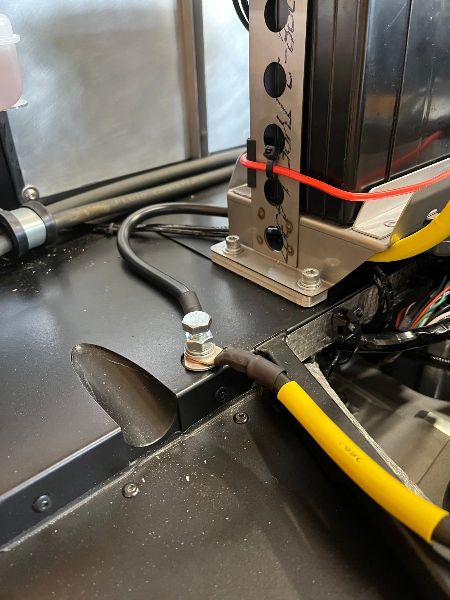
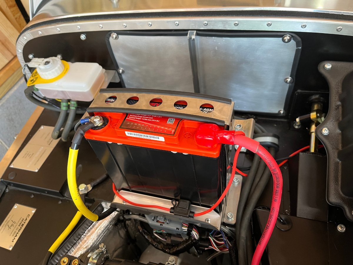
How to jump an Odyssey PC680 battery Before I get to this topic I want to first send a shout out of hope and encouragement to all those of us in the SE USA who endured Helene. I hope y'all and your loved ones are safe and well, your pets and homes intact, and your Se7ens unscathed. Here in the Greenville SC area we suffered considerable wind damage with several large trees fallen on our property, one damaging the detached garage housing Yellowjacket. Fortunately only minor structural damage and the cars are unharmed. One of the effects of Helene was that we lost power for nearly two days (fortunately shorter than many in the area). This power outage triggered the subject of this post. Walking into the garage to take stock of things for the first time after the storm I did my customary Yellowjacket electrics check by switching on the lights rocker (a habit born from the dreaded Banner days). Nothing happened. Another quick check found that when I last pushed the car into position before the storm I accidentally turned on the ignition (to prevent the steering from locking) and left it that way. Now, my Chinese trickle charger does not work during a power outage. It then occurred to me that I had never before thought about jumping the PC680 battery. Now that I did, I realized that it is impossible for regular jumper cables to clamp onto those M6 button screw heads on top. Which brought about another mini-project -- the subject of this post. The ground side was easy. There is an M8 chassis ground bolt on top of the passenger foot well. I replaced it with a longer (40mm) one and a quasi-jam nut. The nut clamps the battery and engine cable ends to the chassis. I first screwed the bolt in until it bottomed out, then backed it up a couple turns and tightened the nut. Done. The positive side is more tricky. After thinking about it for a couple of days I ended up with the current solution. It involves clamping under the positive screw of the battery, on top of the cable ends, a 1-1/2 x 1/2" L bracket with the vertical leg shortened (to reduce protrusion and flex). At present the drawback is that I have not figured out yet a handy removable insulating cover, but the bracket is not at risk of touching the bonnet or anything else. Nevertheless ideas for how to cover it are welcome (other than by electrical tape...). Cheers!

-
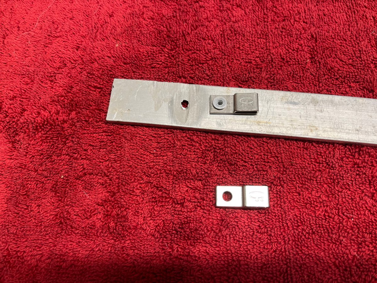
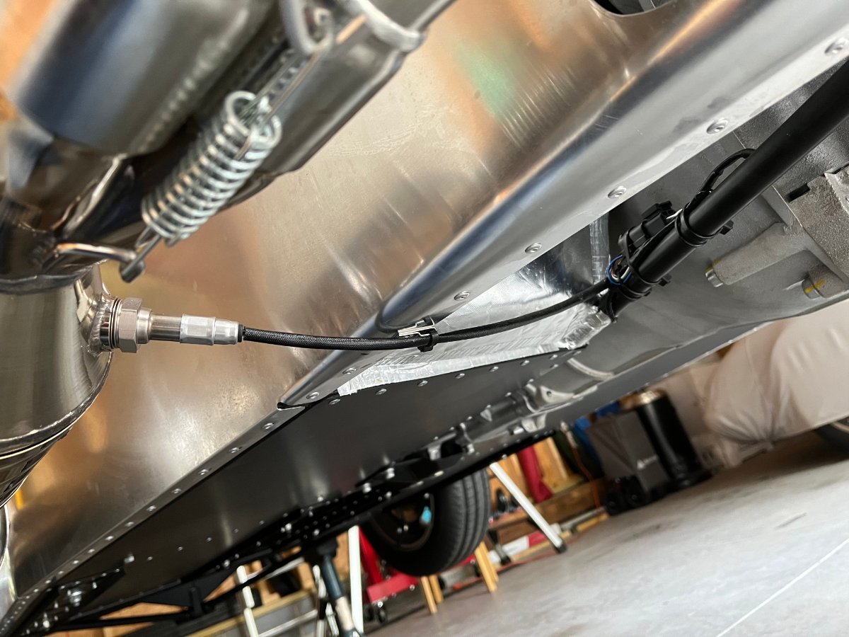
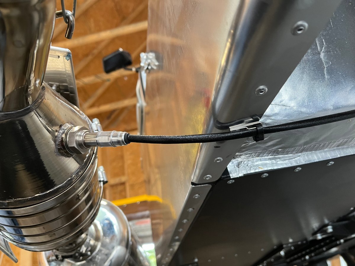
Lambda sensor wire management -- Conclusion Today I drilled out the head and tap-punched the body (unfortunately into the chassis tube) of one of the bottom body skin rivets. In its place I riveted one of the stainless steel zip-tie bases from DigiKey per link a few posts up. I zip-tied the Lambda sensor wire to this base ensuring enough slack to accommodate exhaust motions/vibrations. No problems encountered and I consider the issue closed. Thanks to all who contributed to the solution. The stainless steel zip-tie base, and trial riveting onto a 1/8" thick aluminum profile: Installation on the car: Cheers!
-
Performed a few more process development trials and established a repeatable, capable process . The secret is patience -- very light drill pressure and very low speed. The drill bit eventually picks up the head off the rivet. Then a light punch tap on the shaft and the clean hole is exposed. Only issue is the shaft and bottom part of the rivet would of course remain inside the chassis tube. This will degrade irreparably our highly refined NVH levels... That's where @pethier's approach offers an advantage. Cheers!
-
Paraphrasing Sir Colin: No rivet shall have a free ride!
-
I feel the same way. Thank you!
-
Hello John, Resurrecting an old yet unresolved topic... I am now in a tidying up mode, and this loose Lambda sensor wire has been bugging me, even though it does not droop (yet); it hugs the bottom of the body pretty well. But my OCD side keeps nagging that this is still "wrong". So... I would like to implement your solution of drilling out one of the existing skin rivets and riveting in place a zip tie base. I'm thinking of using one of those below as they are stainless steel, sit flush and allow the rivet gun to react against their surface. https://www.digikey.com/en/products/detail/essentra-components/MTH1-1/3814005?utm_adgroup=&utm_source=google&utm_medium=cpc&utm_campaign=PMax Shopping_Product_Category_Cables and Wires&utm_term=&utm_content=&utm_id=go_cmp-20053924771_adg-_ad-__dev-c_ext-_prd-3814005_sig-EAIaIQobChMIgZXJ4de7iAMVFTYIBR1Jtx5BEAQYByABEgLyZfD_BwE&gad_source=1 My struggle is how to remove cleanly the existing body rivet. I did not attempt it on the car yet. I did some trials installing some pop rivets in a 1/8" thick aluminum profile and then trying to drill them out. Using a drill bit just a tad bigger than the hole I end up spinning the rivet in place... What is your trick to remove a pop rivet cleanly? Other folks please chime in as well. Thanks!
-
Looking forward to meeting at the show. BTW, we are contemplating joining the "Spirited Rally" on Friday the 18th (likely not in the 7).
-
Excellent input! Wondering why buy 2 sticks? To keep the existing one intact as reference and backup in case fabrication fails? Thanks also for the tip re wire rope stick. I actually tried a coiled stick and it is way too flimsy and gets stuck in the tube (buckles and does not make the bend). Sent it back (to Amazon, of course). Great tips, @MV8 !
-
Hello All, Just a reminder - this is a fun and laid-back car show held this year back on the beautiful Preserve at Verdae golf course in Greenville SC. You actually see some remarkable machinery there -- last time on the course I remember, among others, a magnificent Lamborghini Espada and a pristine (of course) 300SL Gullwing. I have registered to enter Yellow Jacket. There is still time to register until Oct 4th. So far not aware of another Seven being entered. Here is the link (once there, scroll all the way down for the Register button...): https://www.motorsportreg.com/events/2024-euro-auto-festival-embassy-suites-preserve-at-verdae-126060?mc_cid=2f26111cc0 Please post here if you've registered or just planning to stop by and spectate. Cheers!
-
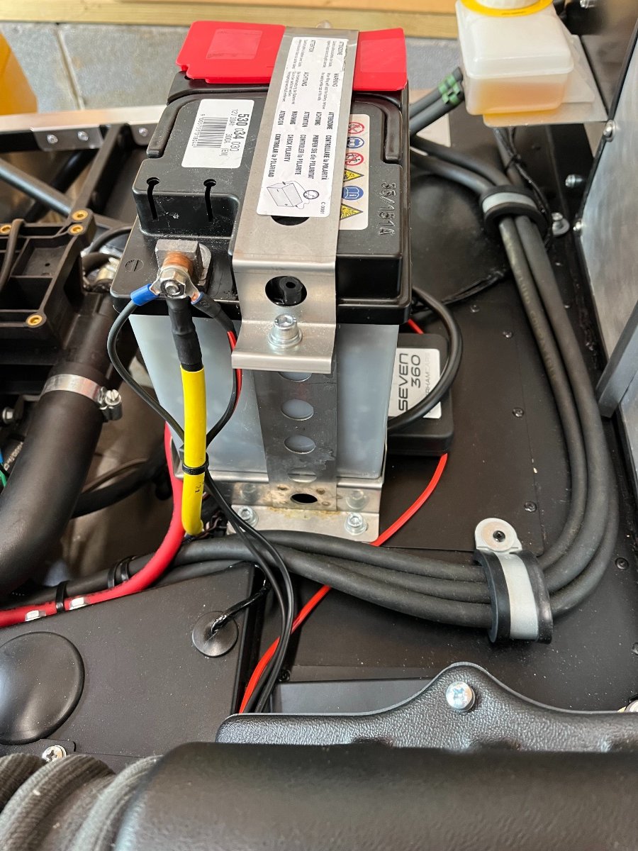
Status report: The Odyssey battery seems to have solved the problem. Due to combination of SC heat and out of town trips, the car was not driven for a whole month. But I made a point of not trickle charging it but rather watch it sit and see what happens. Based on past experience, the Banner would have been depleted over that period. A few days ago I measured the voltage across the terminals and it read 12.9V. The next day I decided it's time and it started right up. This also alleviated the nagging thought that I may have an electrical leak somewhere besides the immobilizer. So for now I decided to continue without trickle charging and just watch how it does over time. The remaining open issues left over from the build are all gauge related: The coolant gauge is dead, the tach is off (hoping for replacements from Caterham), and the dipstick is too short and so far I haven't found a good solution. On the upside, the car seems to drive better every time... Cheers!
-
These look very good! Thank you for sharing. I chose the ones I did because they seemed slimmer (least axial protrusion over terminal) due to my top vs. your side terminals (and because they were cheaper...). Cheers!
-
Added a positive terminal cover from Amazon (trimmed height by about 4mm). Sleeve ID is 10mm but pretty stretchy to pull over and stay in position on the cable. https://www.amazon.com/dp/B088ZT2LFL?ref=ppx_yo2ov_dt_b_product_details&th=1
-
Thanks, @ralph! This sounds consistent with @JohnCh's experience. A Lithium battery will be one of my aspirational future improvement projects... I first need to amortize the investment and work spent on the current AGM solution...
-
@CBuff, thanks a bunch and sorry - my bad -- did not catch the link which was in plain view....
-
Thanks! Looks like you may be running a Lithium battery based on the location of the terminals, or what battery is it? Can you share the Amazon link?
-
Gave up on the Banner battery and completed conversion to a sealed Odyssey PC680 following Josh Robbins' advice. The PC680 was sourced from FCP Euro after 2 failed attempts to get it from 4Wheel Online/Amazon (twice shipped the wrong one). As part of the conversion I replaced the original battery tray and strap (which I had mutilated in a misguided attempt to fit another, wrong battery) with a factory one from Josh, to which I riveted 2 aluminum angle profiles to contain the much thinner PC680 in correct clamp position. Minor rerouting of cables was needed due to the reverse orientation of the terminals required to achieve the clamp position. The PC680 arrived with 13.25 V and the car started immediately. Now just looking for a small well fitting positive terminal cover to complete the job. Cheers!
-

Wanted: Original Battery Bracket and Strap - NO LONGER NEEDED
Yoram replied to Yoram's topic in Parts For Sale / Wanted
@BlueMax, thanks a lot. Josh Robbins was able to locate a new Banner bracket and strap which he can sell to me, so I am all set. Thanks for the offer! Cheers, Yoram -
Looking forward to your detailed account of the conversion! if you don't mind please include a link in this thread.
-
Thank you, @wdb! Very helpful. I'm thinking the same thing. In fact I think that the digital charger I use is for some reason not compatible with the Banner. I do have two of these, one trickle charging my '87 911 for months on end with no issues. I swapped them several times between the 911 and the 7 and they behave consistently vs. the car -- either 911 charger shows fully charged after awhile (2 solid green LEDs) while either 7 one keeps showing trickle charging (lower LED solid green, upper one blinking) forever. Should have cued me into diving deeper into this early on. Duh. Right now my re-filled and recharged Banner seems to have stabilized at 12.8 V (disconnected). I will put it in the car and keep an eye on it. Before and when trickle charging I will have the bonnet off, take voltage readings and observe the cells, and not leave it charging for more than 24hrs at a time. Still looking for a replacement original tray/bracket and top strap. I made my mutilated bracket and strap kind of work for now with longer screws, but am not happy with it. I will certainly look for a better charger - Lessons Learned. Thanks again and cheers! Yoram
-
P.S., my re-filled Banner does not seem to hold charge; in stand-alone disconnected state it dropped from 12.92 V to 12.83 V overnight. Looks like an Odyssey PC680 is next for me too...
-
This ended up an epic fail. Counter to good advice (discovered later) and judgment, I left the trickle charger connected and "unsupervised" for 4 weeks with the bonnet in place. When we came back there was not enough juice to turn on the headlights, let alone start the engine. When disconnected from the charger the Banner read ~2V. I took it out of the car and found only one of 6 cells with fluid (not all the way up), the rest empty. Having decided that the Banner was fried I tried to fit a Duracell SLIU1RXHD battery from BatteriesPlus only to discover that the terminals are too tall... By that time I had modified the battery bracket and strap for all 3 dimensions of the box but neglecting to pay attention to the terminals... BatteriesPlus were good to take it back for a full refund. So next I decided to try and revive the Banner. Got 2 quarts of battery acid from NAPA and patiently filled all cells. I then charged it with my trusty analog trickle charger at 2A for ~24 hrs, disconnected and left it on the bench to monitor whether it holds voltage. So far it's been sitting for ~15 hrs at 12.91V. If it stays stable for another day I will put it back in the car. Problem is that my bracket and top strap cannot be "unmodified" and I need replacement original ones. I posted in the For Sale/Wanted Parts. If any of you reading here have an original Banner bracket and top strap lying around that you are willing to sell and ship please PM me. (I do have all the fasteners.) Once the battery and mounting hardware are sorted I will pursue the trickle charger issue. Cheers, Yoram
-
NO LONGER NEEDED! Looking for an original center-mount battery bracket and top strap for the original Banner battery, like the one shown in the pic. I had modified mine (after the pic was taken) in a misguided attempt to fit a different battery, and now cannot "unmodify" it to revert back to the Banner or accept the Odyssey PC680. Have all the fasteners. Please send PM. Thanks!
-
Trickle Charging This one is quite self-evident but thought I'd share anyway... I left the Se7en in the garage without starting or trickle charging for over 3 weeks, and of course found the battery not able to crank. I suspect the dang immobilizer but given this is a British motorcar and I am the amateur builder it could be anything. BTW, this failure mode was predicted by Josh Robbins (and I'm sure many of you) and I should have listened and hooked it up to a trickle charger; most of it is me being too lazy or hesitant to remove the bonnet... I've already scratched the scuttle a bit in a couple places while replacing the bonnet and dislike this maneuver. So I decided that I need a solution for easy and quick connecting to a trickle charger without removing the bonnet. I got a 1100mA trickle charger with SAE connectors on Amazon. I also got there a 6' dual lead extension cable with ring connectors at one end and SAE connector at the other. I ran the extension cable from the cockpit through the bulkhead hole for the (deleted) heater valve cable and hard-wired the ring ends to the battery. Had to cut the positive wire of the extension cable in the middle because of the fuse housing on it to get it through the grommet and bulkhead hole. Reconnected with a butt connector and used some RTV to seal the grommet. When not charging I shove the capped SAE connector into the side hole in the fusebox cover. Extension lead fuse housing visible at bottom of battery ...the second small negative wire is the whip LED ground. Under dash: At left the bulkhead hole, at right the SAE connector end entering stowage in the fusebox cover. Charging -- SAE connectors engaged. Right side comes from the charger (below). Cheers!
-
Hey Folks, Got an email today about this event with a short writeup. They have a website but it is not updated yet to reflect the new event. This has been a quite good near-annual car show and this year's venue is the best - it's the beautiful golf course next to the Embassy Suites Preserve at Verdae in Greenville. I thought it would be fun to have a small (or large?) contingent of Se7ens exhibited in a group. Registration has not started yet. It should not be too expensive - last time I exhibited (another car) a few years back I think it was $75. I sent an email to the organizers requesting to know when they will have the website updated and registration open so I can enclose a link in this thread. In the meantime it would be fun to know who all here might be interested to show their Se7ens, so please chime in. I plan on bringing mine. I will post here anything new I learn. Cheers, Yoram