Yoram
-
Posts
283 -
Joined
Content Type
Profiles
Forums
Store
Articles
Gallery
Events
Library
Everything posted by Yoram
-
Guys, thanks a bunch for the quick and great responses! @fastg, in Simple Green I assume you are referring to their all purpose cleaner, correct? @wdb, thanks for the pad info. Both the 7448 and the 6448 are classified as ultra fine, and the 6448 as "light duty", whatever that means. Will this combination deliver the matt / satin finish I'm after and not a shiny one, or a brushed one as @mrmustang mentioned? --> What about rubbing out light scratches? Thanks again.
-
Question re aluminum skin finish / polish Happy New Year Y'all!! As I mentioned last year I'm fixin' to post some compilation of lessons learned from the build, but I first need to organize them a bit better offline... However, in the meantime I got a question regarding upkeep of the aluminum skin: I do not want to get the finish to be shiny. I want to keep it matt/satin, but get it more uniform, get rid of witness marks such as from the protective film, eliminate irregularities. I also want to be able to buff out minor scratches and then blend with the rest of the surface. Seeking recommendations for products and methods folks have found to work. Thanks!!
-
Scott, I moved them to the end of the main post.
-
Sure! All of it is generic stuff from various sources. Just need to dig a bit... Links added at bottom of main post.
-
Hahahaha!!!!
-
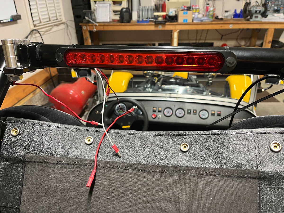
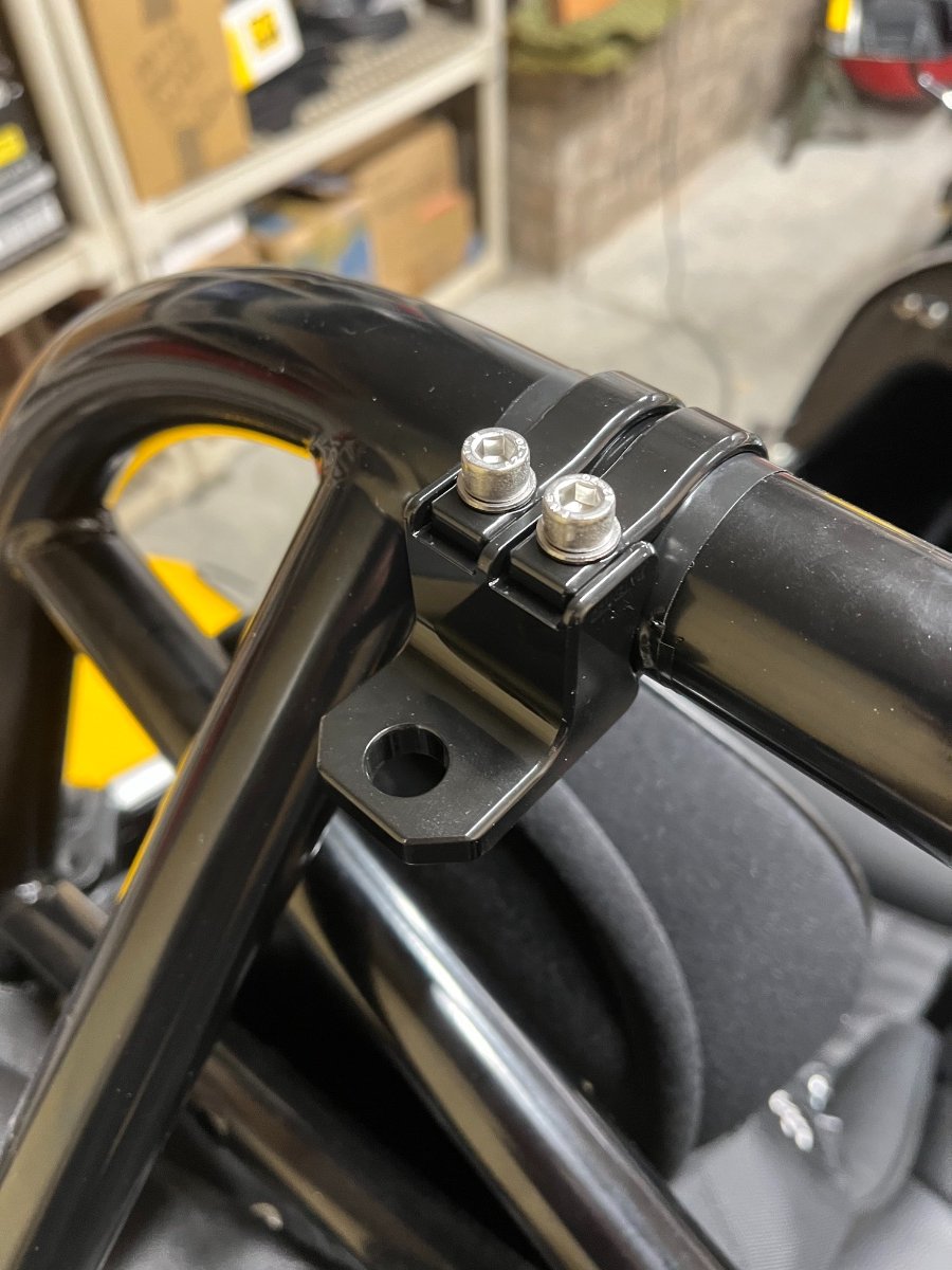
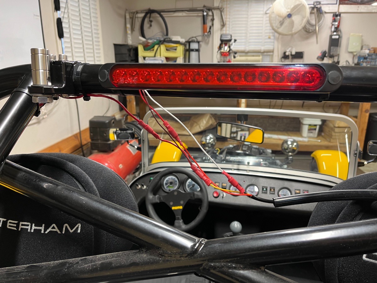
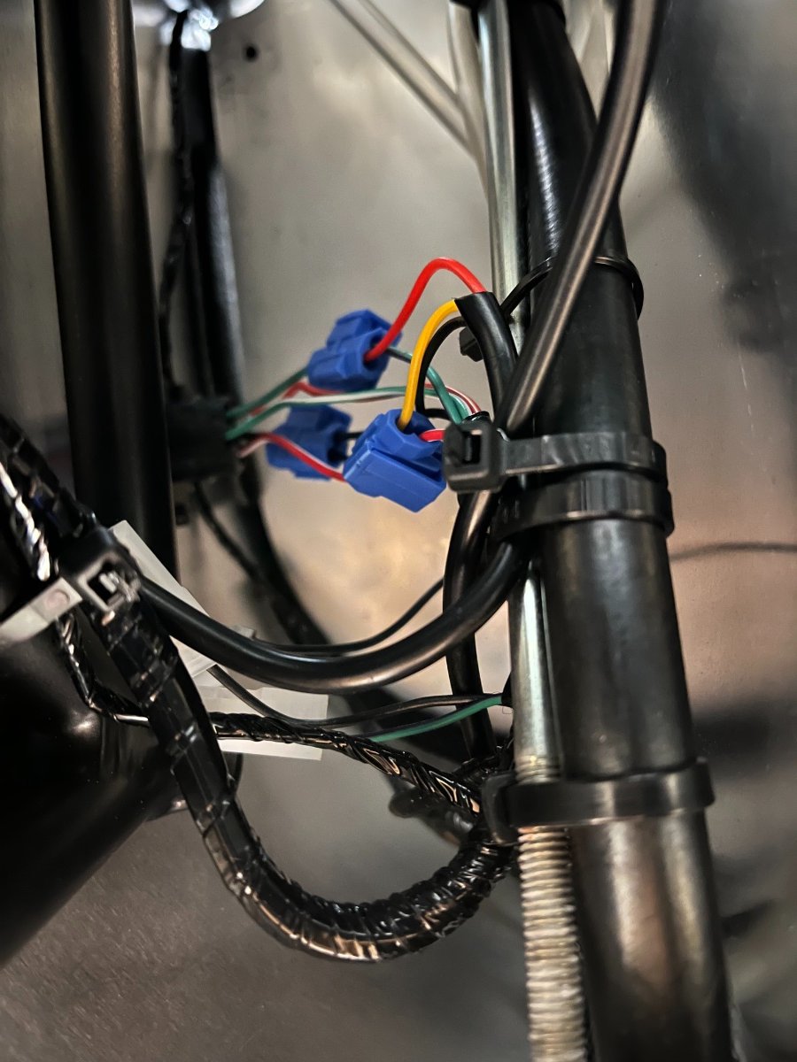
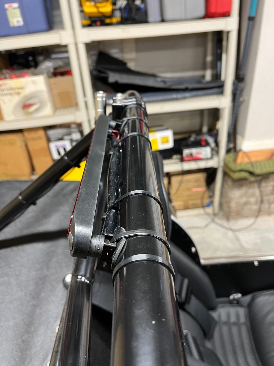
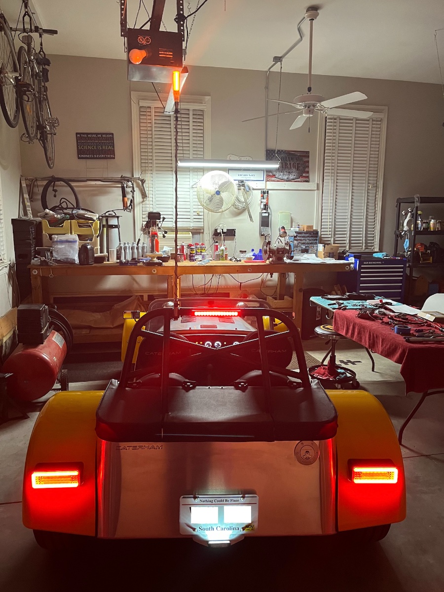
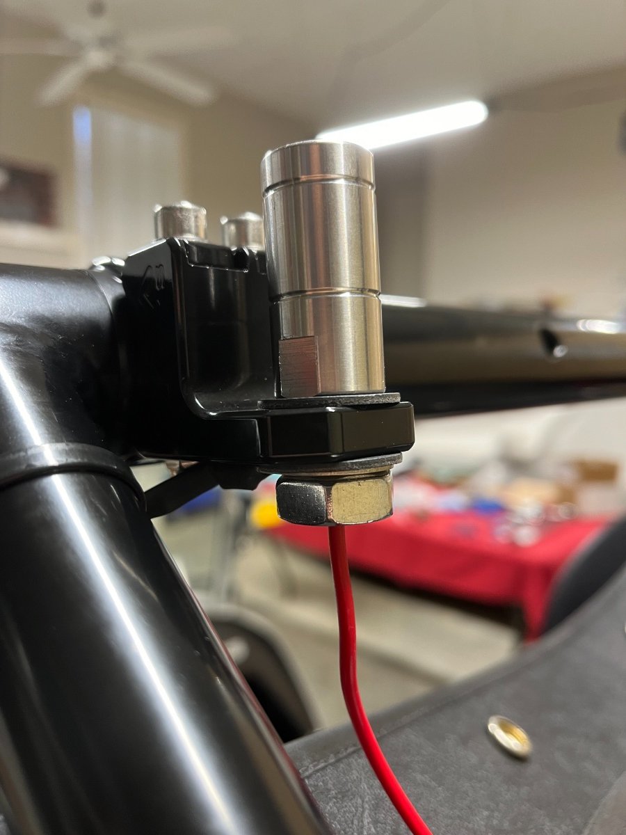
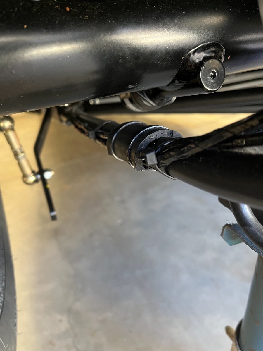
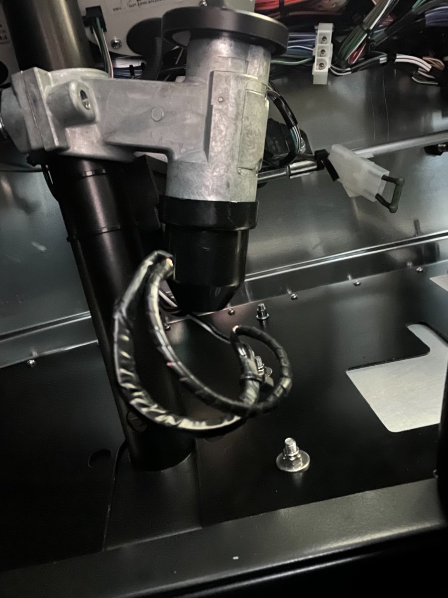
High mount brake light and lit whip For enhanced safety I decided to add a high mount center brake light and a whip with an amber LED light on top. The latter so I am not forgotten and driven over by some jacked up RAM 150000 stopped behind me at a traffic light. The center mount LED light I found on Amazon has both brake and running lights LEDs so it uses two positive feeds and a ground. I used an 18 gauge 3-wire sleeved cord for the splicing and ran it up the RH roll bar brace. I found the easiest place to splice into the rear lights loom is in the right rear corner inboard of the wheel well. This loom also carries a ground wire. Identifying the wires is quite easy when disassembling the connector inboard and outboard of the wheel well wall (which you need to do anyway to access the wires for splicing) and checking voltage across the pins. My wife agreed to climb in and press on the brake pedal for the brake wire... Below: spliced wiring tucked in place (view up from underneath). The new 3-wire sleeved cord is in view right below the splices. The whip came from Buggy Whip following a tip from one of the members here. It has a center positive feed wire and is supposed to use its mount for ground. I have it wired to the same running lights positive feed but to a separate ground through the unused fan switch (heater delete), so I can turn it off if some law enforcement agent finds it objectionable. The "just in case" wire I ran early on through the tunnel from under the dash to the trunk with some extra lengths proved handy for the whip ground. It runs up the LH roll bar brace to the whip base. I kept the existing fan switch ground wire, cut its other wires and connected them to the "just in case" wire. To ensure the whip does not ground through the roll bar (and to protect its finish) I insulated the mount with electrical tape: Below: Whip mount with base. Note red positive wire which will connect to the shared running light positive feed, and the ground wire ring terminal right above the nut. The whip screws into the base and makes (+) and (-) contacts through an RCA connector. I used disconnectable male/female round connectors, male on light fixture side, female on feed (car) side. Below: center light and whip mount ready to connect to the 3-wire feed cord. Center light and whip connected, before tidying up. Silicone sleeve on the right will slide over the connections: Below: My twisted method of attaching the center mount light to the roll bar involves two stacks of spacer washers, zip-tie mounts, larger rubber washers against the roll bar for grip and paint protection, and zip-ties... (I have an idea how to improve on this but it is a bit pricey, so this will do for now.) And silicone sleeve in place to conceal the connections behind the center light: The whip I received has a bad internal ground; awaiting replacement from Buggy Whip, hence the coiled black patch wire, if you zoom in. Sources for the main bits: The center mount brake+running light is from Amazon: https://www.amazon.com/gp/product/B09HWS1C61/ref=ppx_yo_dt_b_search_asin_title?ie=UTF8&psc=1 The 3' fiberglass whip with top light is from Buggy Whip (you need to "build" your own kit -- check the menus at top of the webpage): https://www.buggywhip.com/collections/fiberglass-whips/products/fiberglass-whips-with-lamp-holder These folks are super helpful and will answer all your questions. The 18 gauge 3-wire cord is from Amazon: https://www.amazon.com/gp/product/B0C6HYJ4CF/ref=ppx_yo_dt_b_search_asin_title?ie=UTF8&th=1 The 9mm ID Silicone tube I used as a sleeve to hide all the mess behind the center light is from Amazon: https://www.amazon.com/gp/product/B085N2BF91/ref=ppx_yo_dt_b_search_asin_title?ie=UTF8&th=1 The two zip-tie mounts for the center light are from the Caterham kit. Not sure where all they want me to use them... The rest -- connectors, washers, splice terminals, fasteners -- is at your favorite local (or online) hardware stores (usually takes more than one place and trip to collect it all...) Cheers and Season's Greetings!

-
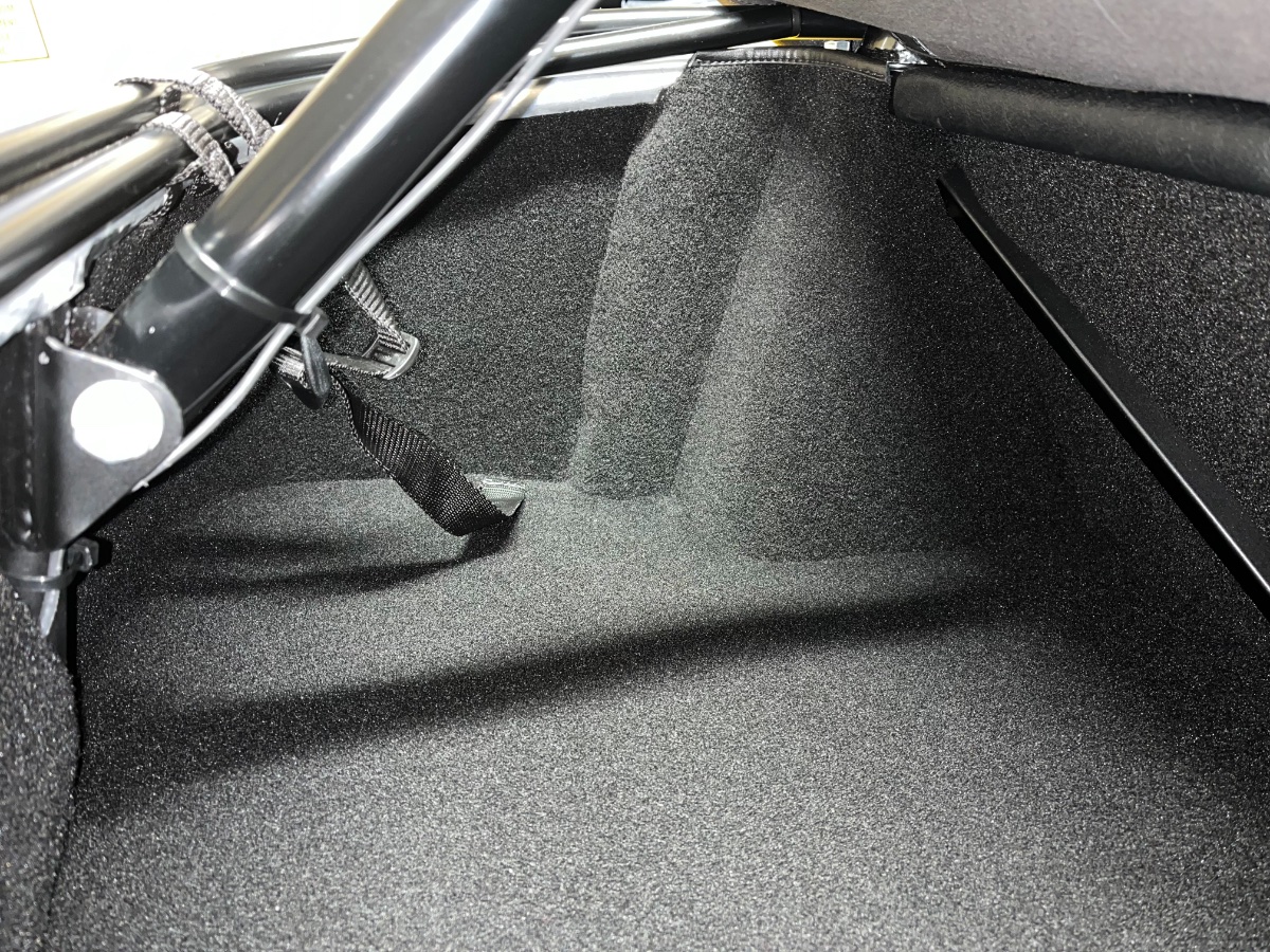
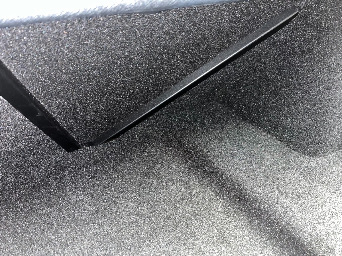
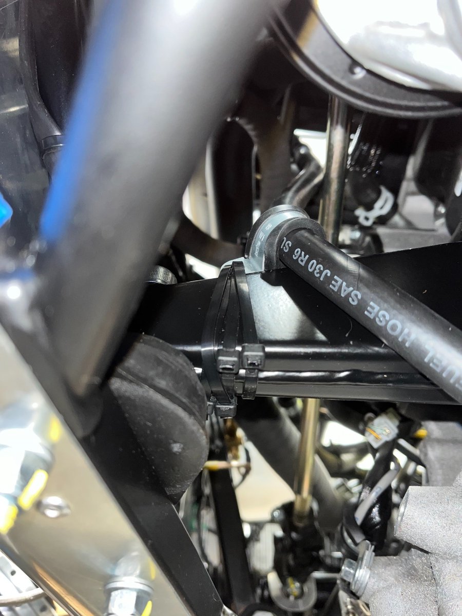
Hello folks, Hope everybody is well and excited about the Holidays. I am coming back healthwise... not quite 100% there yet but most of the way, and the doc says give it time. Been gradually able to resume work on the car over the last couple-three weeks. My build is just about done (very mixed feelings). In this post I will cover some of the loose ends that got finally tied down. Title and Registration I have a SC title and a personalized plate! The process took some time but was not too bad. It involved, after submitting the paperwork, two visits to my house (garage), one by a Law Enforcement Officer (could have been also a DMV agent), and one by a DMV Compliance Auditor, each to look at the VIN on the chassis, compare with the paperwork, and sign a different form. One would think that in small government SC they would look for a way to eliminate one of these signatures... On the other hand it was a great surprise that both times they were willing to come to the car at no extra charge and save me the cost and headache of trailering it to the DMV. And the last odd thing is that neither visit involved any technical or functional inspection... (When I read in the guides and in Chris Collins' blog about the IVA, I shake my head. The pendulum never seems to stop in the middle...) Anyone in SC facing this step feel free to PM me and I'll be happy to walk you through it and forward you the forms. Trunk trim Completed trunk trim - walls and floor. Gorilla-glued the edge of the rear bulkhead cockpit carpet which had lifted. Used carpet tape for front and rear wall pieces, and Gorilla glue for rear edges of forward side pieces and top of small center triangle. Floor carpet took perhaps 20 trimming iterations to get it to fit… Dipstick "calibration" This has been "work-in-process" for quite a while, previously reported in this thread. The issue is that the dipstick does not show the oil level correctly because it does not reach deep enough into the sump. In fact, initially the dipstick would not register anything with the sump full. I tried several steps of shortening the guide hose, which eventually ended up getting the level to show at maybe 1/4 when actually full. Problem is that with each shortening, the guide hose gets closer to the steering shaft and requires measures to ensure it doesn't touch. So today I took another step and cut one more inch or so off the hose. This brought the displayed level to ~1/2 with the hose just about touching the shaft. I loosened the plenum bolt that secures the top bracket of the dipstick hose and rotated the bracket clockwise as far as it will go (not very far...) to alleviate some of the tension in the hose. I also placed an adel clamp on the hose just above the engine mount bracket and tugged on it as far outboard as I could with 4 zip-ties wrapped through its hole and around the engine mount bracket. I hope to improve on the zip-ties but am declaring the dipstick calibration issue closed with actual "Full" reading displayed as 1/2. Rear assist rebound bumpers I have previously observed and reported that with the rear suspension in static full rebound (chassis on jack stands), there is a vertical gap of only ~3mm between the deDion tube and the chassis rails. My concern is that during dynamic rebound events with greater deflections in the coil-over top and bottom mounts, the deDion tube could be hitting the rails. Per good suggestion by @MV8, I zip-tied short lengths of slit high pressure hose on top of the rails under the tube for protection. The next post will cover the installation of the high mount (a relative term on a Caterham...) center brake light and 3' fiberglass whip with LED top light. Cheers and stay well! Yoram
-
Update and Joyful Thanksgiving! A couple weeks ago I lost my footing and fell during some yardwork and banged my head on the driveway. Recovering from a concussion after a night and day at the trauma unit. According to my neurosurgeon I am on the path to full recovery but It will be several more weeks before I can expect to feel back close to normal. Makes you realize how fragile life is, who are your true friends, and what really matters... especially around this wonderful Holiday. Looking forward to stepping again into the Caterham, but obviously remaining progress is delayed and will be slower than anticipated. Progress since last post: Swapped submarine sender for a new one received from Denver - no change; culprit is temp gauge; Denver is working on replacement Switched tach dipswitches around and collected OBD II vs. tach RPM data - in "best" setting tach reads ~350 RPM high at idle (~1300 instead of ~950) but a near constant ~200 RPM low up the range; Denver is inquiring with the factory Secured zero deductible agreed-value collector car insurance coverage with American Modern (considerably less expensive than Haggerty) Received my SC title; ordered and awaiting personalized license plate Ordered and received center mount LED brake light and (separately) wiring and connectors from Amazon * Ordered a roll-bar-mounted 3' fiberglass whip with strong amber LED top light (BuggyWhip.com) * Ordered and received custom build plaque from PlaqueMaker.com; will post once riveted in engine compartment * will post an update on splicing into the rear lights wiring loom and installing both lights. I also intend to compile and post here a collection of my top Lessons Learned and what I would have done differently in hindsight. In the meantime, my sincere thanks to all of you for following and contributing to this thread over the last year (almost to the day!). I learned a whole lot from many of you and much of my car has benefited from the collective wisdom on this forum. Wishing you and yours a Safe and Joyful Thanksgiving Holiday, surrounded by whom and what you love. Cheers, Yoram
-
It seems to me that it should work. Not 100% sure whether the "drp adapter" includes a longer M5-0.8 screw or a an M5-0.8 male thread that threads in place of the original windscreen frame screw, but since they call it the SPA Caterham Mirror Mount sounds like that's what it does. I think your path will be easier than mine.
-
John, thanks a bunch for your quick and helpful response. Much appreciated!!
-
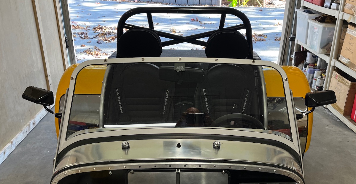
Side Mirrors A few weeks and posts ago I reported my spectacular fail attempting to install the garbage aftermarket side mirrors supplied by Caterham. I since ordered, received and installed a pair of Lifeline MSA Formula mirrors which this post is about. I threw away the original mirrors that came in the kit, except I decided to keep the Caterham adapters that came with them, and modify them to accept the MSA mirrors. Each MSA mirror is designed to attach with a single 1/4"-28 screw inserted from inside the body into the female thread in the MSA mount. Then the base of the mirror threads onto the outer thread in the mount and gets fixed to it by 2 tiny grub screws. So, I decided to add 1/4"-28 threads onto the original Caterham mirror adapters and keep their attachment feature to the windscreen frame with their M5-0.8 threads (replacing the frame middle screw). Not having a lathe I took the adapters to my favorite local source -- Harris Machine Shop in Greenville. They determined that they could not (or did not want to) cut the 1/4" threads, but were able to turn the adapters down to the major diameter (nominally 1/4"). They also made a holder that I could place in a vise into which the adapter threads with its original M5-0.8 end. That way I could cut the 1/4"-28 thread myself with a manual threading die. For some reason I now have a 1.94 MB total file size limitation which does not allow me to enclose enough detail with adequate image quality (I'm guessing I used up my lifetime file size allocation with this "blog"), so I am enclosing a link here for the steps and results: https://www.dropbox.com/scl/fi/qz7s7juthw39b9ce84qne/Side-Mirrors.pdf?rlkey=arpgu9nijvlilujevnqsuyu07&dl=0 Below is one pic of the completed installation: All seems well but I have yet to test the mirrors in driving, especially for vibration and how well they hold their adjusted positions. Will report soon. Next are roll-bar mounted center mount brake (and running) light and whip with LED on top. Cheers!
-
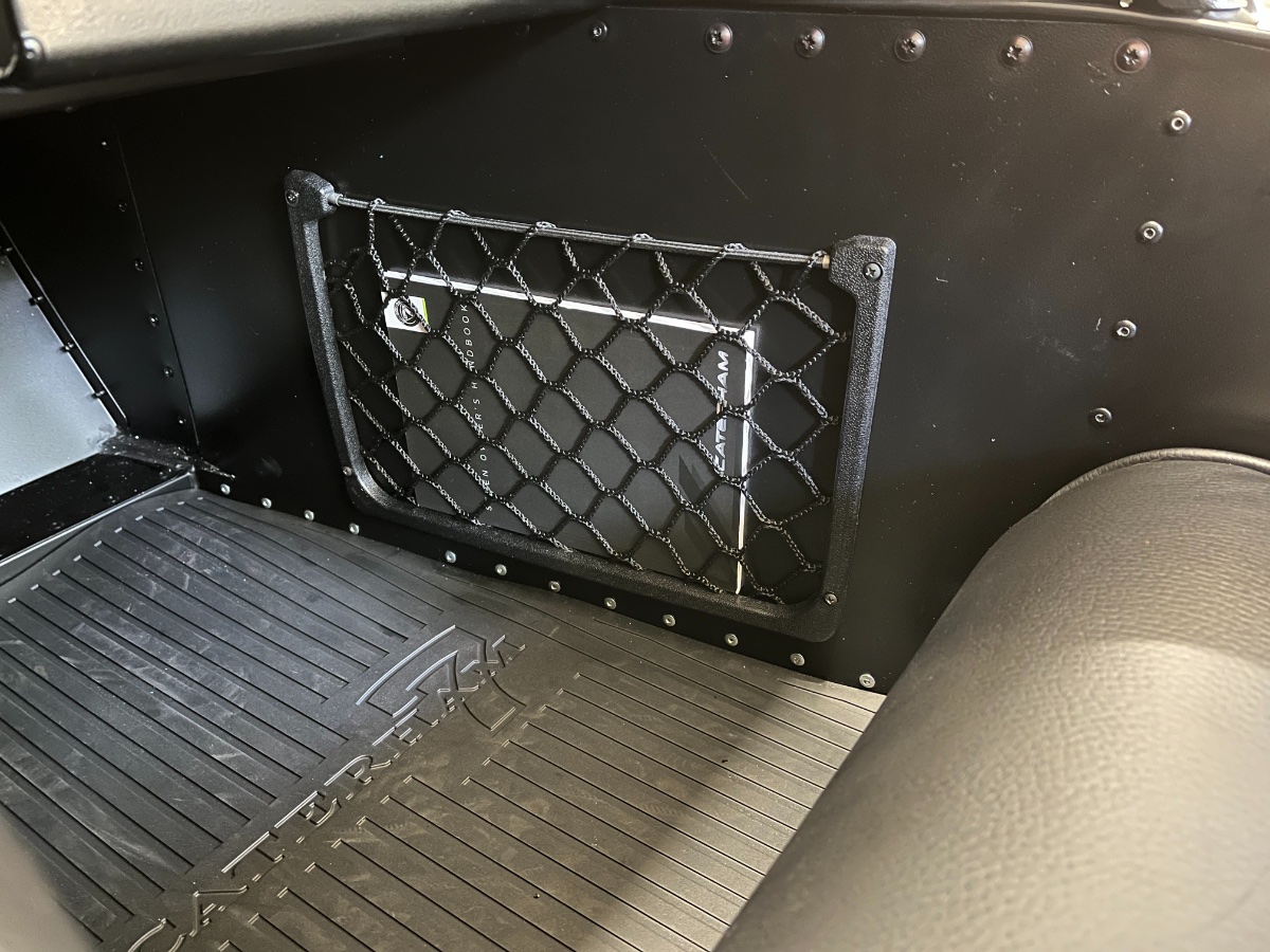
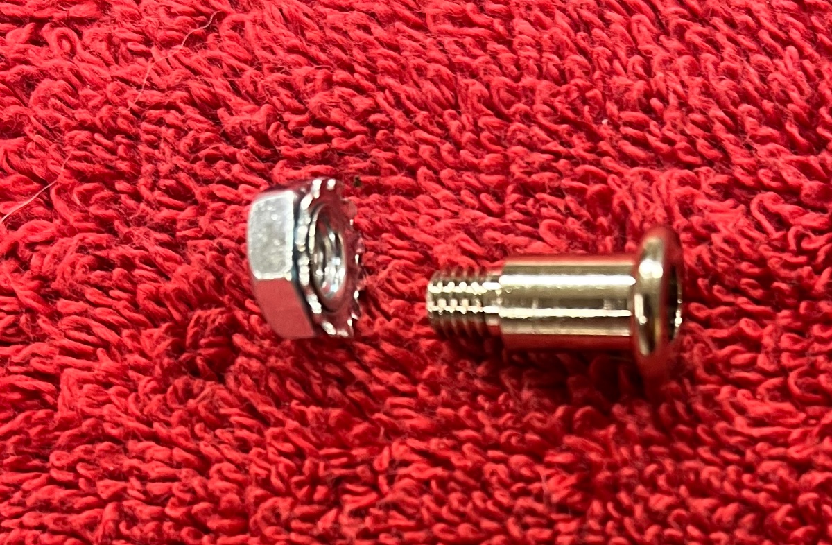
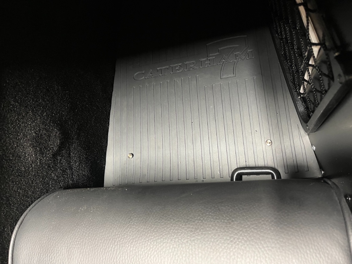
A couple of interior tweaks: Map pocket / storage net When I ordered the kit I checked the box for the Map Pocket. It arrived as a generic aftermarket piece which you can get on Amazon for 20% of the cost (80% less). Anyhow, I finally came around to install it. I mounted it in the passenger footwell on the outer wall. I used #6 x 1/2" sheet metal screws. 3/4" length would have been easier but I was intent on adding lightness. Could not find black sheet metal screws in those sizes so bought a small pack of stainless ones at HD, screwed 4 of them into a small board and sprayed the heads flat black. The pocket holds the owner's manual and can hold a small purse and an iPhone... Floor mat retaining studs The Caterham-supplied rubber mats are quite thick and seem pretty well wedged on the floor due to the trapezoidal shape, so I was hoping to leave them alone. However, after a few short drives we saw them "buckle" and slide forward, mostly I think due to the entry and sit down maneuver, which involves dragging our heels forward on the floor as we lower ourselves into the seats. After some search I came across (no, this time not on Amazon!) floor mat studs that looked OK. The source is Millworks Hot Rod and the stated application is 1928-1931 Ford Model A... Not sure what makes that application so particular. Luckily it seems to work also on a Caterham Seven... The studs come with lock nuts (captive serrated washers), 4 per kit. The threaded stem is quite short and does not leave enough height for any extra washers, and the shoulder is quite narrow, so you want the hole in the floor to be pretty tight, just big enough the let the stem through. You want to drill the mat holes a bit smaller than the stud head. If, like me, you don't play well with others and choose to work solo, tightening the inboard passenger side stud (or both) is easier before installing the muffler, but it can be done afterwards as in my case. Next steps are side mirrors, center brake (and running) light, and a whip with a top amber LED light. Wiring stuff on order... Also dipstick and coolant gage calibrations. In parallel, waiting to hear back from the SC DMV to my initial submission for title and registration, so driving options are quite limited for now. Cheers!
-
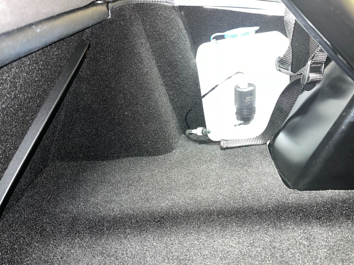
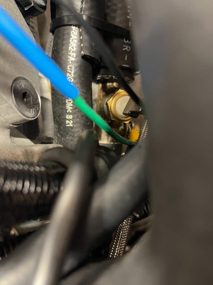
Coolant temp reading update In looking for possible causes for the discrepancy in readings, I repositioned and rotated the submarine and placed insulating hose sections between its hose and the adjacent hose to ensure sender housing is not even close to touching anything around it: I then repeated the OBD II vs. gage comparison during temp run up at idle. Nada. Got identical results: Denver suspects the sender rather than the gage and are thinking of mailing a replacement. I'm not excited about draining the system and pulling the submarine out and refilling... Would prefer instead to add a cheap potentiometer between the sender and the gage and “calibrate” the gage to match the OBD II data in the zone of interest (100-120C). Not a clean solution but a cleaner job... and conceptually the same — manipulating resistances to get a desired visual... We'll see.
-
I look at this one differently. I don't have the data sheet for the gage (submarine) sender, am too lazy to search for it, and it could also be off, rather than or in addition to the gage. The OBD II data falls in line with what I read so far about Duratec temps, and I tend to trust the ECU sender in the head more than what seems like an aftermarket gage sender (not sure why they have both - either redundancy which obviously doesn't help when one is off, or Caterham wanted an analog gage and it was easier to concoct the submarine than patch into the engine ECU looms) . The senders are also only a few inches apart in the circuit so there is no reason for a big difference between them unless one or both are off. So in my mind the path is first try to get a replacement gage under warranty. If that doesn't work or solve the issue put a pot in series with the gage, adjust it to match the OBD II in the region of interest (100-110C) and leave it under the dash.
-
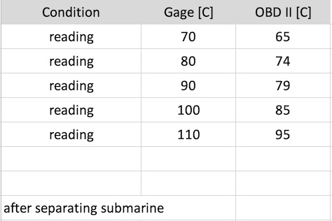
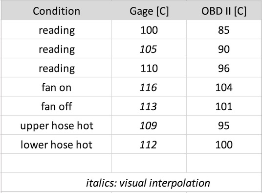
More Cooling Stuff With the high coolant temp readings I have been seeing, I hooked up the OBD II scanner, started the car in the open garage and let it idle. Here is the data I collected: Looks like the gage (or the submarine sender) is a bit off... Awaiting assessment from Denver... Cheers.
-
Very helpful!! I will hook it up later today to the OBD II scanner and see what the ECT readings are compared to the gage, especially when the fan kicks in and out, and go from there.
-
Awesome info, Ralph! Thanks a bunch. Re high brake light, I looked more closely and there is no practical way to run the wires through the bar, which renders my first question moot. I am familiar with identifying and splicing into existing wires. The barrel nuts are a great idea! Re the spare wire through the tunnel, this was a decision "just in case" before buttoning down the console so who knows, it may stay there forever as is, subtracting lightness... Re mirrors, just picked mine up from the post office - a pair of Lifeline MSA Formula convex, black, from Demon Tweaks. Seem quite similar to yours. Working on a simple adapter to mount them in place of the middle screw on the side of the windscreen. Will report out. Not worried either about not being able to swing the door out 90 deg. Thanks again for the great info and your car looks way cool. Cheers!
-
Thank you!!!! Converted above to Celsius... Very helpful! Looks like yours in not getting as hot as mine. My fan kicks in and keeps it in the white (non red) zone but a bit higher than I'd expect. I'm wondering whether my thermostat is too high. I also read about folks putting 85C thermostats in place of the standard oner which is referred to as 100C. Found a very interesting writeup here: https://purplemeanie.co.uk/index.php/2017/10/21/build-session-27-more-bleeding-coolant/ One idea I got there is to confirm the coolant temp with an OBD II scanner, which I may do next. We'll see what Josh Robbins says... Thanks again!
-
Good tips about splicing into the rear lights! Did you run the wires inside the roll bar or zip tied to it? My car does not have a center brake light at this stage nor side mirrors yet. I have submitted the paperwork for titling and registration last week and don't know how this process will play out. Generally SC is quite lax but I definitely plan on having a center brake light and side mirrors, regardless. Just in case, I ran a spare double wire through the tunnel before covering it up and have the front few feet bundled up under the dash and the rear few feet bundled under the trunk floor -- if I decide to tap into the power supply to the relays and fuses and use a relay (like for trailer lights) or such.
-
Yes, but I want it to be higher. Again, my biggest concern is being completely hidden in front of one of those jacked up (or even not jacked up) "personal" trucks. I am a bit less concerned about being visible from a distance with lights on and my yellow wings...So it will need to be some kind of a rod or pole sticking above the roll bar. I was thinking of mounting a pole/whip at the unused LH shoulder harness point. Thanks! Yoram
-
P.S., A pet peeve of mine is flatbed tow trucks driving around with their "emergency" white/yellow lights on. I get it when they are pulling over, loading and pulling out, but driving with a car (not an oversize load) strapped on a flatbed is no different than a truck with any standard load. I guess if they can get away with it I should be able to as well with my little life saving strobe (should I still decide to go that way).
-
Yeah, I see the issue... I don't want it to be super bright, so I think I am getting off the strobe idea, but I want it to be really high up, above the hood height of the common monster truck. So in my mind some sort of a mast, pole, or whip is a prerequisite, and hopefully hollow to run wires up to a small yet reasonably bright omni-directional light. Thanks for sharing this!
-
This looks awesome! Says it has a lamp holder and obviously a hollow mast for wires! Bookmarked! Definitely a candidate. Thanks a bunch!!
-
Very funny!! Yup. All very good points. I'll probably go with a bright constant amber light, not a strobe. But then again... looking at what all is driving down the road in these parts... blue headlights, purple neons, light bars, lift kits in front only aiming at the sky, flesh cutting spikes out the wheels etc etc, I doubt anyone will give a $hit about my little strobe....
-
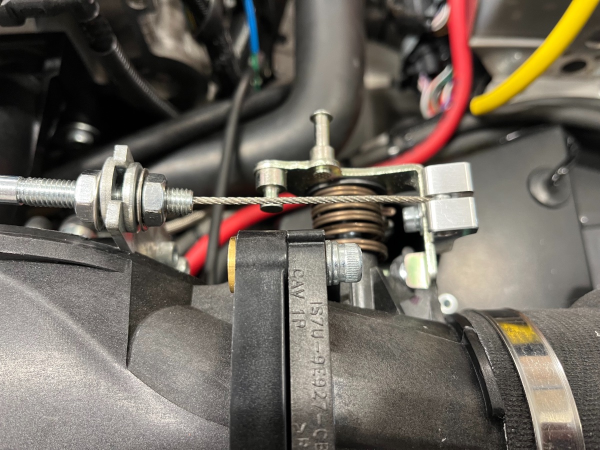
A few fixes, tweaks, findings... Tach misreading I noticed that the tach wouldn't read above about 1200 RPM when I revved the engine to what sounded like 4000 to 5000. (I do not rev it that way yet but did briefly under no load just to verify as was not seeing almost any response.). Josh Robbins suspected tach was set for the 420 instead of my 360. Per his guidance I pulled it out and set dipswitch #2 in the back to off. That took care of it. Immobilizer drama Right after/due to the tach fix, I encountered one of the more annoying conditions to date - no start. It first started fine right after the fix when the tach was still dangling off the dash. Then, after I tucked everything back in and installed back the steering wheel the car wouldn't start - no response at all from the red button. Long story short (and another Josh R correct guess) - while futzing behind the dash I dislodged the Immobilizer antenna. I now have it secured back with a zip tie around the ignition switch near its face, but there are times I need to shove the little Sterling fob backwards towards the antenna for the system to acknowledge it. I already deeply hate the Immobilizer and want to remove it altogether or at least disable it permanently. Saw some posts on the forum on the topic from about a year ago and also shared my sentiments with Josh R. He is acutely aware and lobbying Caterham to eliminate it from future US spec cars. Planning to revisit once I get through most of the rest of the To Do list. Idle speed adjustment Edited - originally mis-reported due to dyslexia/brain fart. Revisited and addressed per the below. Again per Josh, the voltage across the throttle position sensor at idle should read 1.13V. Stuck back-probes in the back of the connector and it showed 1.3V a perfect 1.13V with maybe a +/- 0.003V fluctuation. Left it alone. This means the throttle opening needed to be reduced. Started by screwing in the stopper screw (vertical screw under the inboard end of the throttle, need to turn engine off and rotate the throttle open to access) all the way down. Then adjusted and retightened the throttle cable length (nuts in front of the throttle pivot) to ~1.1V. Finally backed the stopper screw up in small increments until reached 1.13V and tightened the nut underneath it. Cable length adjustment nuts on the left, stopper screw on the right under the end of the cable. The wires to back-probe are the white/gray (center) and the pink/black (bottom) As a result of the small cable length adjustment, I am now missing 2 deg of full throttle opening as measured with a digital level on the throttle lever (pedal stop hits before throttle stop). I think this is quite good and am leaving it as is. You don't want the throttle cable to tug against the throttle stop under the weight of your foot. Dipstick misreading I believe I mentioned in a previous post that while I know I have exactly 4.75 quarts in the sump, the dipstick was barely registering. I cut just about 1" off the bottom of the guide hose in two steps and the oil level now reads ~1/3 of the range. Obviously the ID of the guide hose is bigger than the OD of the dipstick so they are not behaving like a push-pull (e.g., bicycle brake) cable, and there is room in the hose for the dipstick to bend more than the hose and therefore a hose length change does not translate to an equal change in dipstick reading. So to reach perfect calibration I need to cut more off the hose. Problem is that shortening the hose reduces its bend and gets it closer to the steering shaft. It is now about 3/8" away. Yes, there are ways to pull it away but I don't feel like disassembling the plenum to dive in there. So I'm leaving it alone for now and will await an opportunity or inspiration to revisit. Mental note for now: 1/3 of dipstick range is Full! Open issue (or not?): Coolant temp Took a 10 minute drive in the neighborhood yesterday with my good friend and neighbor, leisurely pace but between the two of us around 400 lb payload... The coolant temp rose up to and settled not much below 110C (end of the "OK zone"). On the upside, coolant level is now stable near the Max mark and no leaks. Josh had mentioned that the Fords run hot -- up to 105-106C. Concern is it was maybe 70-75F outside and light load... What would happen at 100F charging up the mountains. Wondering what temps folks with 360 and 420 cars are seeing. Upcoming tweaks: Side mirrors, floor mat studs, map pocket, strobe light+mast? Cheers!