Yoram
-
Posts
283 -
Joined
Content Type
Profiles
Forums
Store
Articles
Gallery
Events
Library
Everything posted by Yoram
-
Round where I live an annoyed Bubba might pull a gun. I'd rather be more passive aggressive...
-
Not too excessive... an option.
-
My nagging fear is getting stuck first in line at a long red light or railroad crossing, and a big RAM 1500 with 20" lift kit pulling up behind me and by the time the lights change he forgets I'm there (once stopped behind me he cannot see me at all). Thinking of attaching a long thin flexible post on a spring base (like old antennas) at the open top seat belt mounting hole, with a strong strobe light on top like in school buses... Less than half-kidding! Seriously, anyone has any experience or ideas where to source something like this? I don't want a flag as it raises a racket flapping at speed.
-
Thank you! In my case the studs on the spacers are identical thread to the ones on the hub. I confirmed this before purchase. I am using the lug nuts that came on the spacer studs to tighten the spacers to the original studs, and the original lug nuts to tighten the wheels on the spacer studs. In fact, it would have been impossible to use the original lug nuts to tighten the spacers to the hubs as they are way too tall to fit under the wheels.
-
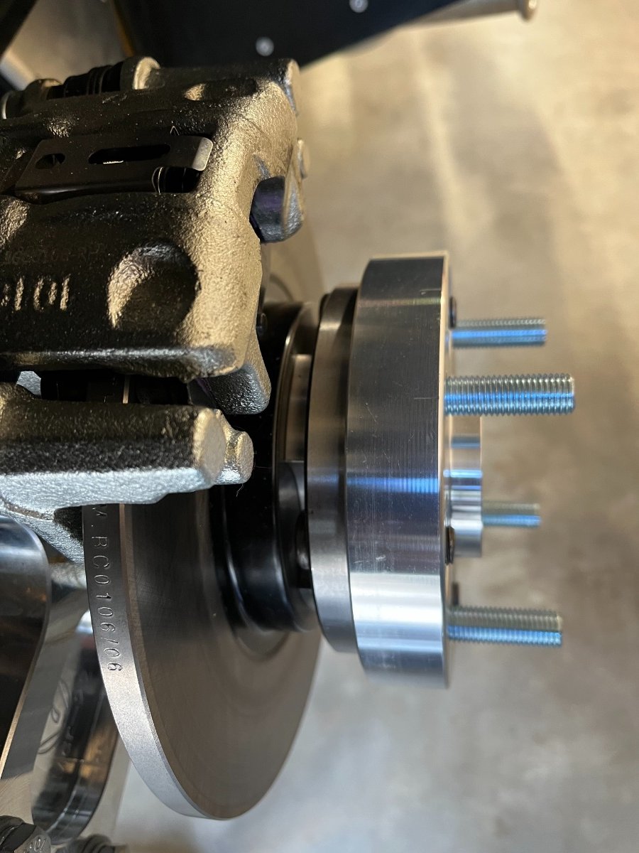
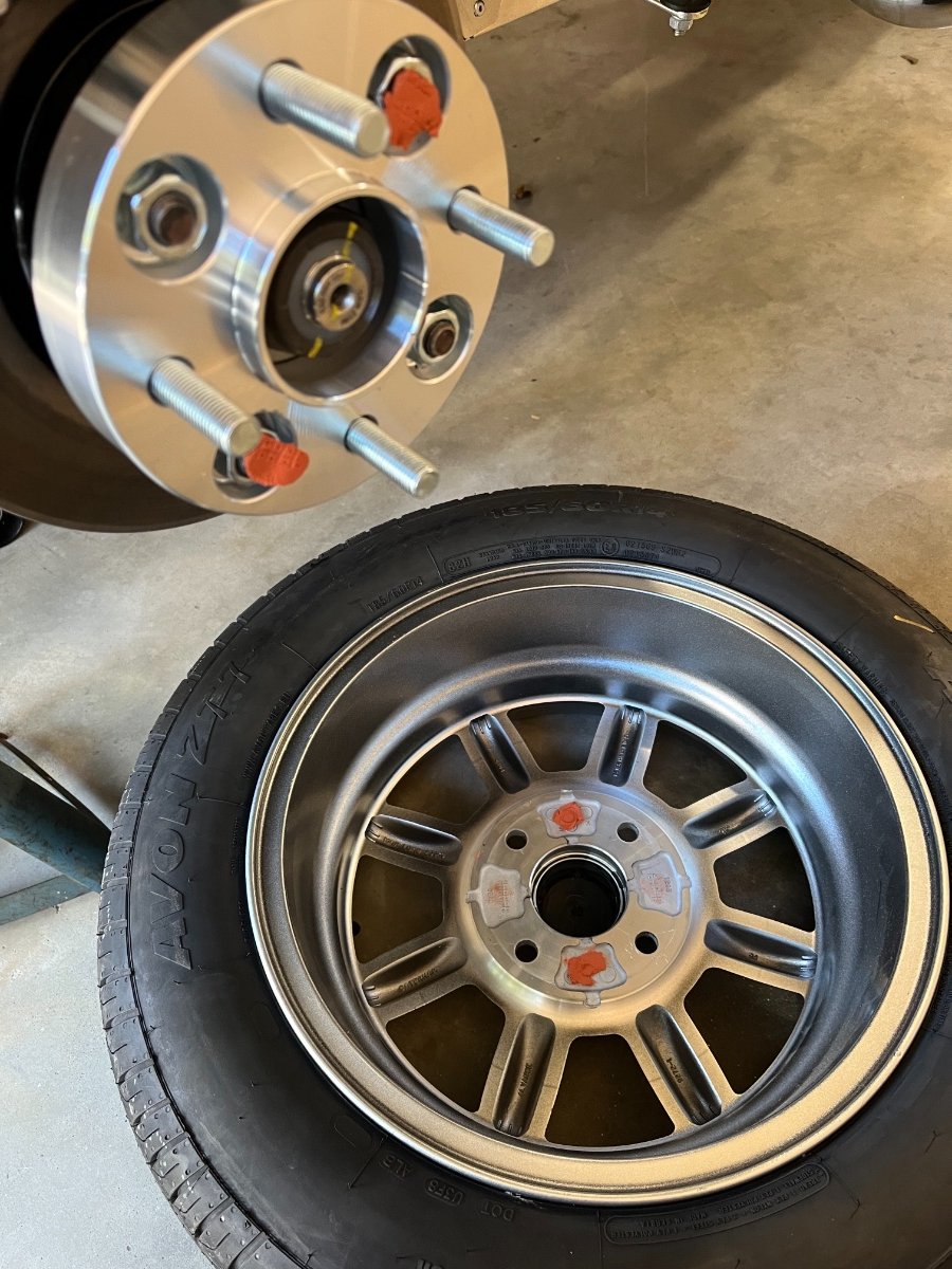
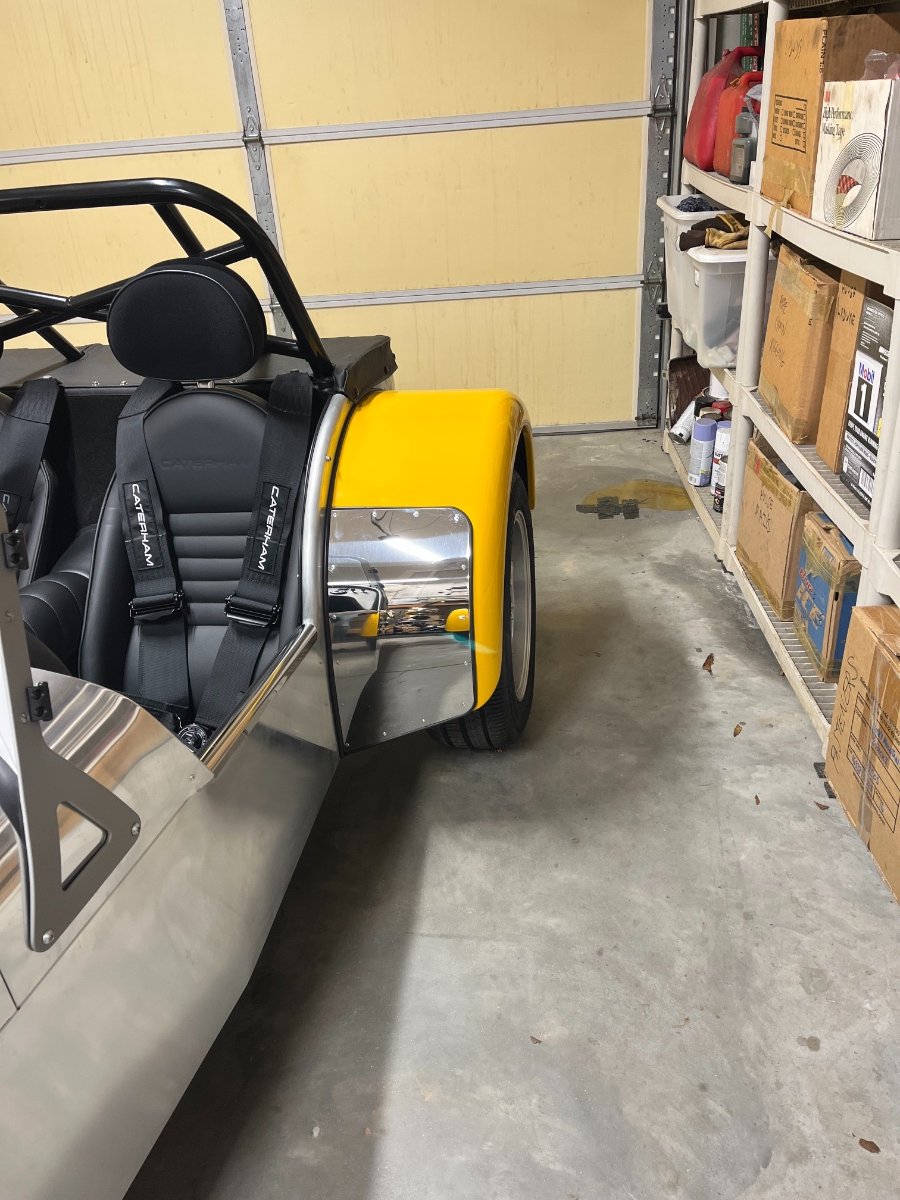
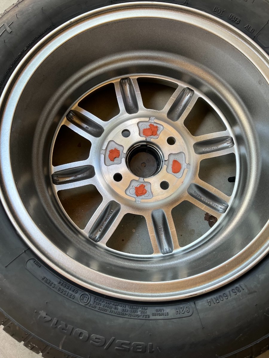
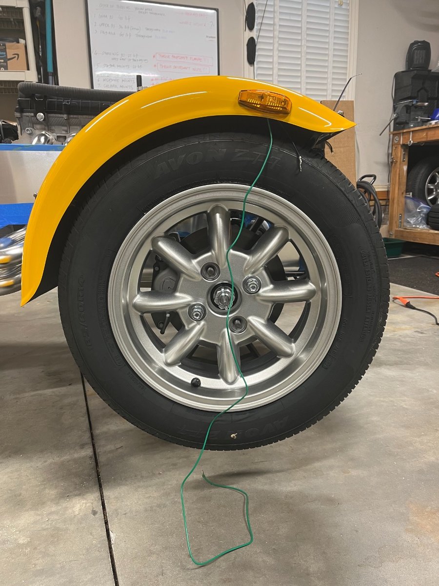
Rear Wheel Spacers I know this is a controversial topic and am anticipating good comments. So... I decided to add spacers for the rear wheels for purely visual reasons. The stock wings and 14" wheels (185 cross section tires) on the 360 make the rear of the car look very wimpy (to my eyes of course). However, I do not want more tire because I like the vintage feel of building noticeable slip angles even under relatively moderate cornering. So, the main considerations for a spacer are the right thickness for wheel fit within the wing and avoiding or minimizing modifications to the existing studs. After some figuring and searching I found 25mm thick hub-centric aluminum spacers which mount on the existing studs and come with their own studs and nuts (clocked at 45 deg). The key dimensions are 108mm stud/hole circle dia, 63.4mm centering dia, 4 x M12-1.5 studs, 25mm thickness. https://www.amazon.com/dp/B09QBSZJK6?psc=1&ref=ppx_yo2ov_dt_b_product_details 25mm seems optimal here in using the available wing width without the wheel sticking out. It also provides good thickness under the added retaining nuts and for their height. (I've looked at a 20mm version which of course has less meat under the nuts, and the nuts themselves shorter.) A critical point was to verify that the existing studs would not crash into the inner surface of the wheel. The length of the existing studs is 27mm, which means they stick out of the spacer by 2mm as can be seen below. I measured the 4 recesses in 2 wheels multiple times as best I could with calipers and came up with a consistent ~2.5mm, which is promising but close... So I decided to confirm clearance with modeling clay similar to checking valve to piston clearance in engine builds. I installed and torqued the spacer on the hub, placed some clay in the 4 recesses of the wheel and mounted and gradually torqued the wheel. Upon removal and inspection I found the 4 clay globs showing healthy remaining thickness. I'm comfortable that the original studs do not contact the wheel. I cleaned off the clay and mounted and torqued the wheels. Since I widened the rear track by 50mm and therefore reduced a bit lateral weight transfer, I stiffened the adjustable rear stabilizer bar by one hole from my "benign" starting point (went from 2nd lightest to 3rd lightest). Actual/final setting is of course subject to driving which I have yet to do. However, the visual result to my eyes is very satisfying: BTW, I've had a very similar setup at the rear of my '87 911 for the last 14 years with no issues. Cheers!

-
Done. Thanks!
-
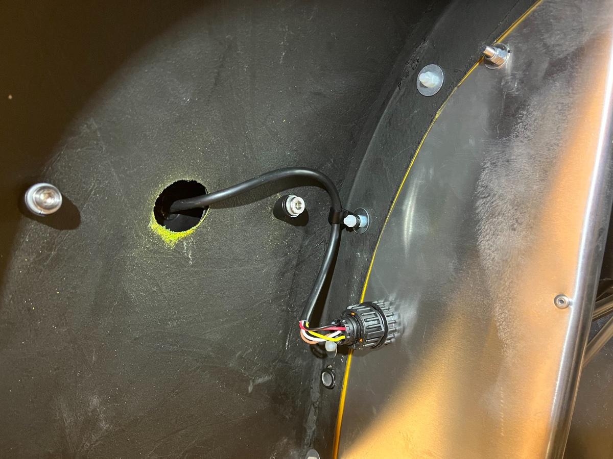
Rear lights wiring - minor clean up Small stuff but thought I'd throw it in for completeness. 1. Secured the rear light looms (which run along the lower chassis rails) on the outside of the rails to eliminate risk of pinching -- above by deDion tube at rebound, inside by coil-over mount at rebound, below by jack. 2. Per @mrmustang's good prod, added grommets to the holes in the rear wings for the tail light looms. Couldn't find the correct size so cut larger grommets to fit. Cheers!
-
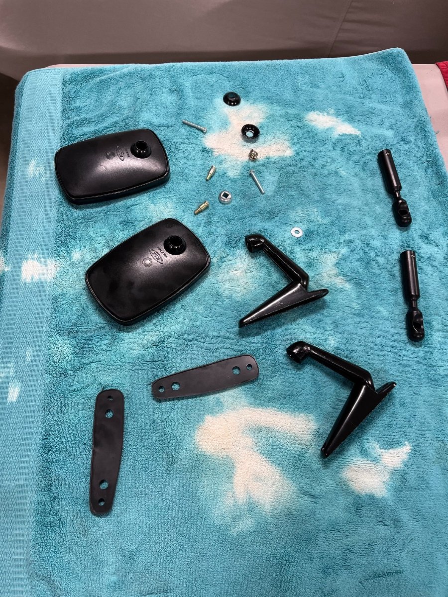
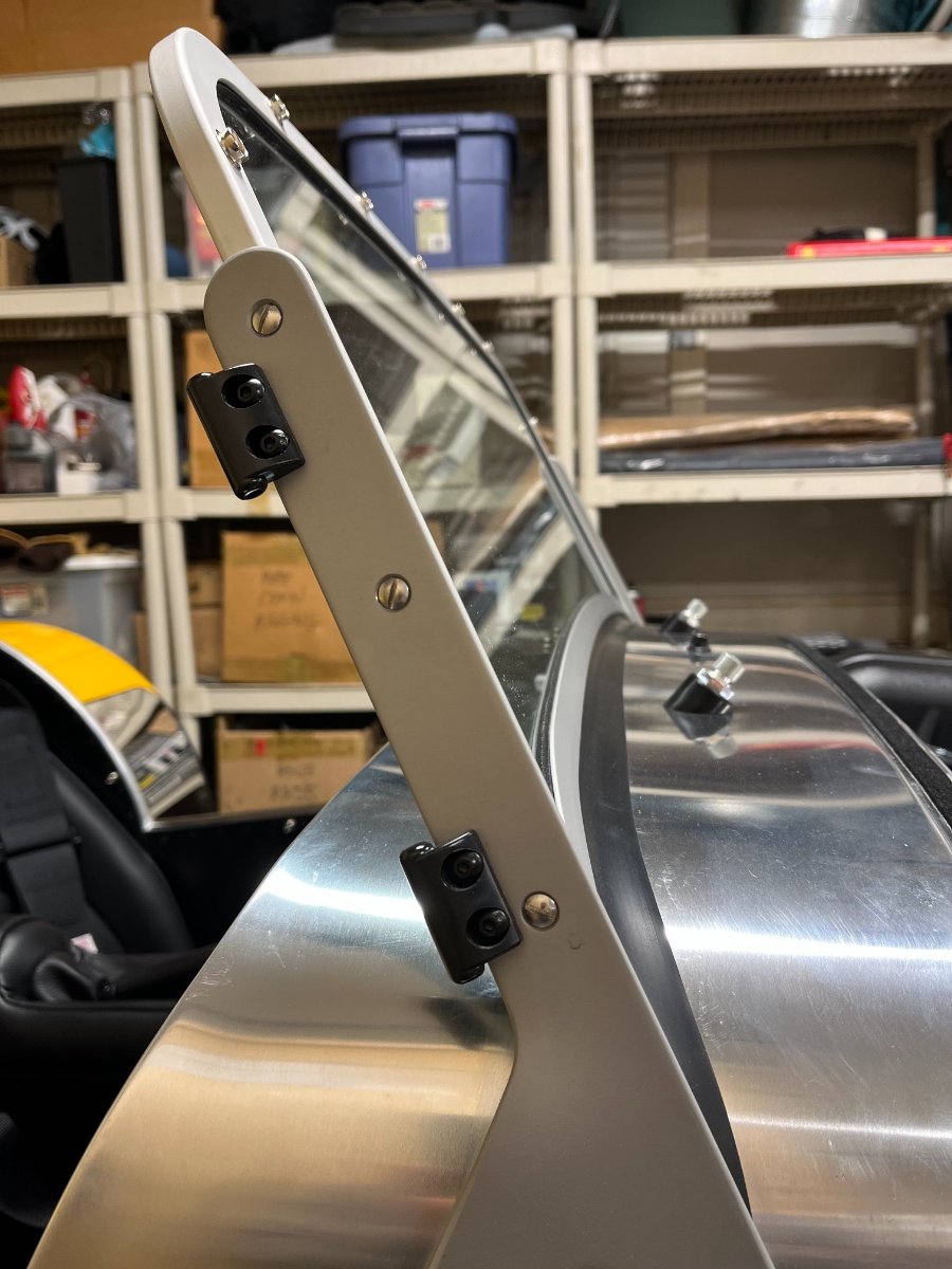
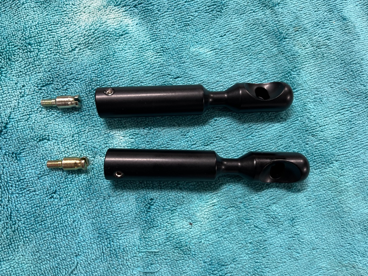
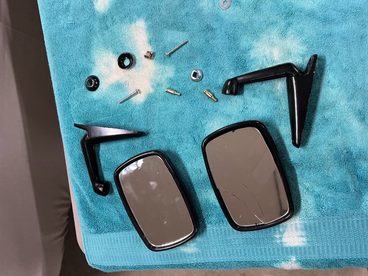
Mirrors trial 1 (Fail) Now that I'm preparing to have the car registered and start driving on public roads it's time to install the side mirrors (or wing mirrors as the Brits call them although they don't mount on the wings). The kit comes with a set of 2 aftermarket (door or wing) mid-sixties' style mirrors, and 2 Caterham-designed stays and mounting screws. You are supposed to unscrew the AM mirrors from their stems and screw them onto the Caterham stays. The Caterham stays attach to the middle thread up the side of the windscreen frame by an adapter screw and a setscrew. The little devil in the details is that once you unscrew the AM mirror from its stem all the backing hardware inside the mirror comes loose and goes to rest at various corners of the housing. The nonchalant tip in the IKEA guide is to "unclick the glass" (and then install the mirror housing on the Caterham stay and snap the glass back). The little problem with that is that the glass is glued to the housing, and it does not "unclick". It chips and breaks when trying to pry it off. No biggie, but this is the shoddiest piece of kit in this kit. I have a pair of single mount Lifeline MSA Formula mirrors on order from the UK. Will need to come up with some kind of adapters to attach them to the intended middle thread in the windshield frame. I will of course post progress. Middle screw on the frame is replaced by an adapter screw to carry the Caterham stay: Caterham stays and adapter screws: AM mirrors after "disassembly": ... and after "unclicking the glass"... In summary - garbage (literally). Mirrors on order: https://www.demon-tweeks.com/us/lifeline-msa-formula-mirror-244324/ black, convex. Cheers!
-
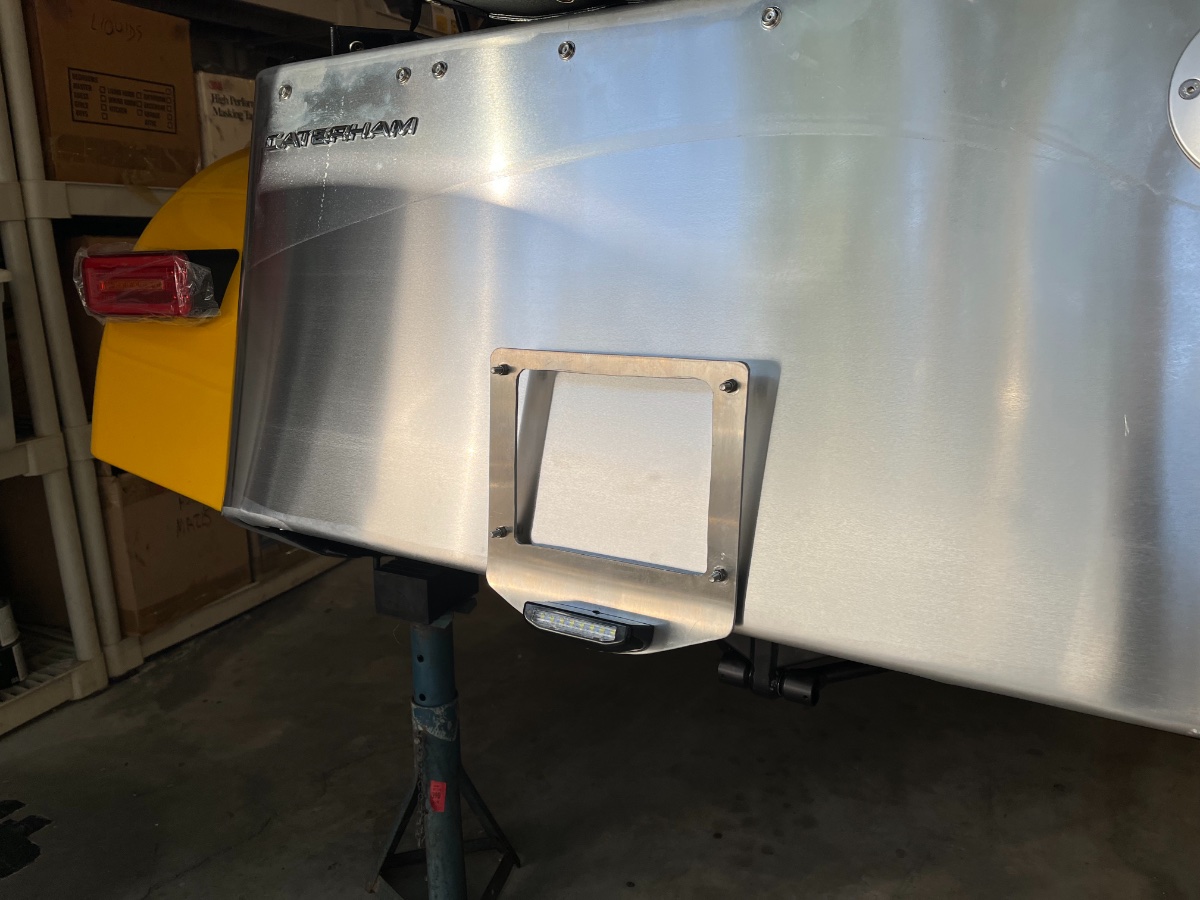
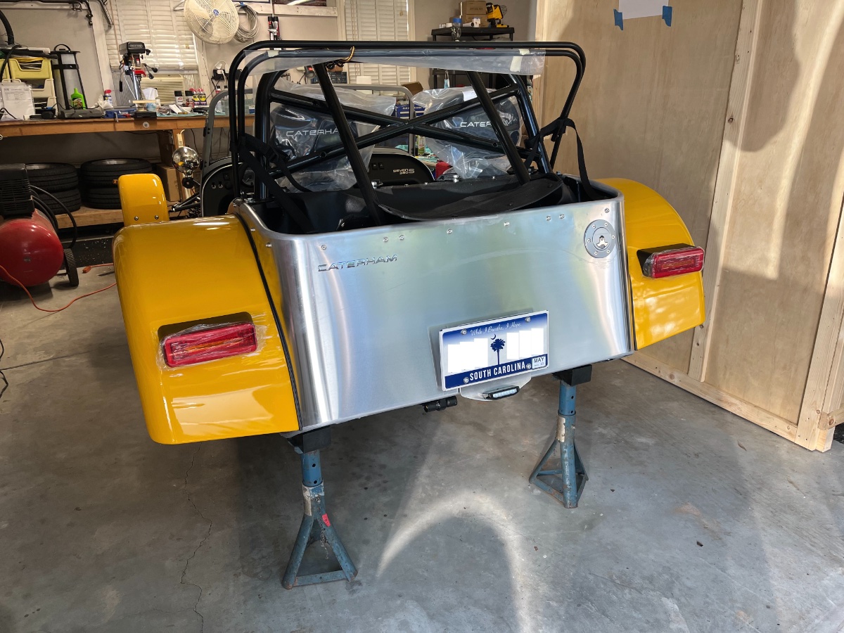
... and one more backlog post... License Plate Bracket (and light) The kit comes with a nifty little combination license plate+reverse LED light fixture which installs with 2 screw on a bracket pre-welded to the chassis below the skin. However it does not come with a license plate bracket. But you do not want to drill the rear body skin and besides it is not vertical. I did quite a bit of searching and found nothing I thought I could adapt to the Se7en, so decided to fabricate one. I wanted it to be stiff, light, corrosion resistant and to bolt under the above light fixture sharing its bracket and screws. I proceeded to fabricate it from a 8" x 12" x 3mm aluminum plate, with a large window cutout in the center to "add lightness". Used a drill press, small electric jigsaw and Dremel rotary and contour sander tools. My biggest problem was bending the plate to allow the license plate to sit vertical. Using clamps and a water pipe clamp as lever I ended up with a curve rather than a tight bend which raised the license plate above the light by 1". I decided to let it be. Due to the narrow gap between the bracket and the body at the bottom I installed the license plate mounting screws (M5-16 stainless steel, left over from front wing mounting) from the back side and jam-tightened to the bracket with nyloc nuts under the license plate. The license plate will be secured with nylon nuts (left over from rear wing mounting) with stainless steel washers on both sides. Installed the bracket and light on the car along with an expired plate to verify fit and alignment. Seem to work OK. Tucked the short loom and connector up above the lower chassis rail. I am hoping to have the car titled and registered next week! Cheers!
-
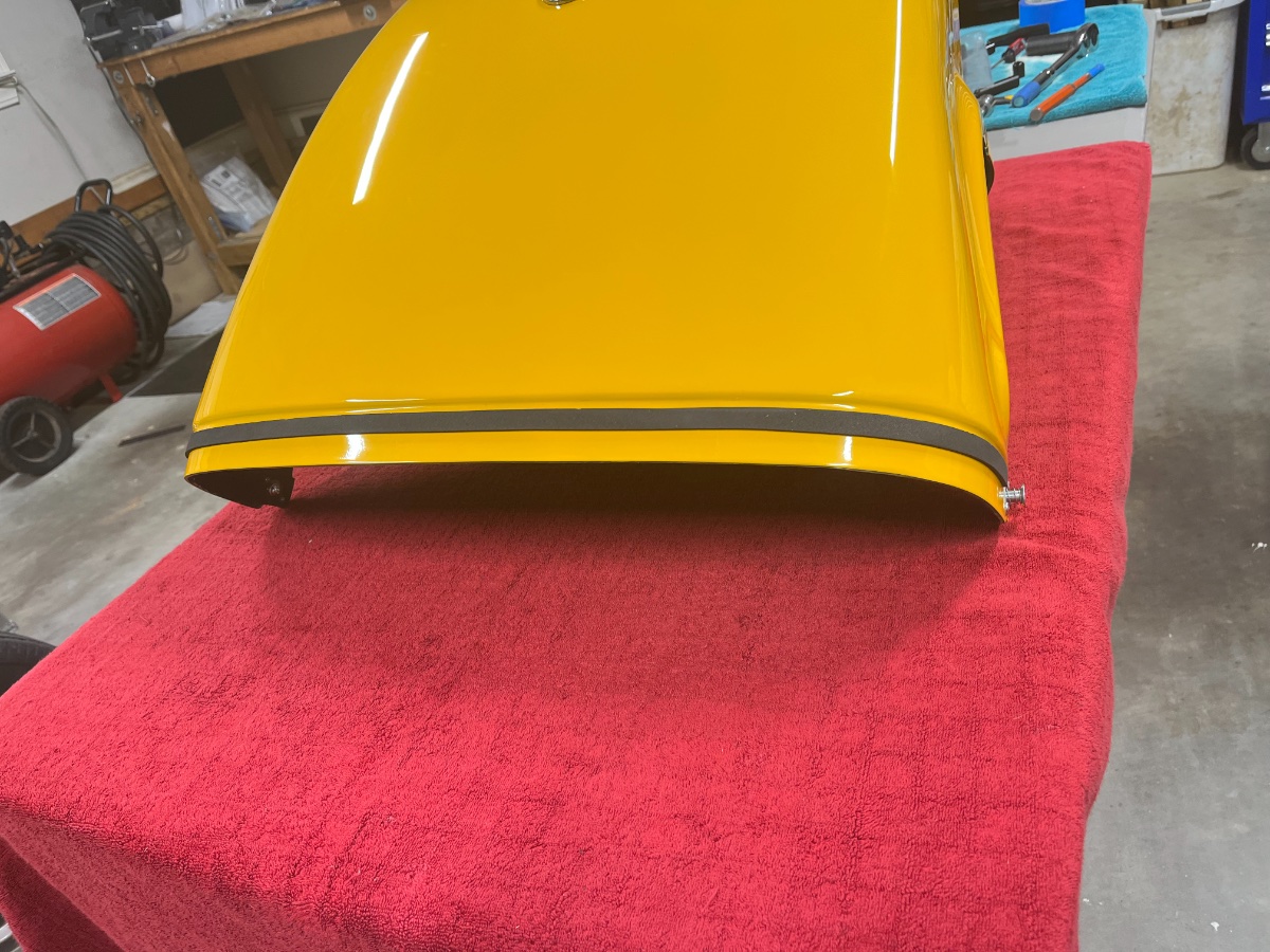
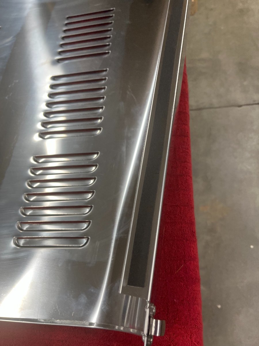
Another posting backlog item predating the first drive: Bonnet The only tedious part about this one is peeling off the blue protective film from the top surface. Applied Amazon-sourced 1/2" x 1/8" high density black self adhesive foam strips (instead of the crap supplied in the kit) to the nose cone and the bonnet's long edges. I found the best way to lay the bonnet down onto the car is to hold it on both sides in its target orientation (one arm stretched over it) and then lower the rear edge onto the scuttle. Then, with the rear edge resting on the scuttle, move forward, grab the front side ends and pull them apart a bit to clear the nose cone as I lower them into position. Obviously the nose cone needs to be secured in place before putting on the bonnet. Clamping the bonnet down with the 4 latches is straightforward. I am thinking of adding clear film on the skin behind the front ones to prevent scuffs. 8 October edit: Had some leftover silicone hose I used for cushioning the front wings on their stays, and decided to try to use short pieces as body skin protectors over the springs of the bonnet front latches. I may actually leave them on like this, or not. Cheers!
-
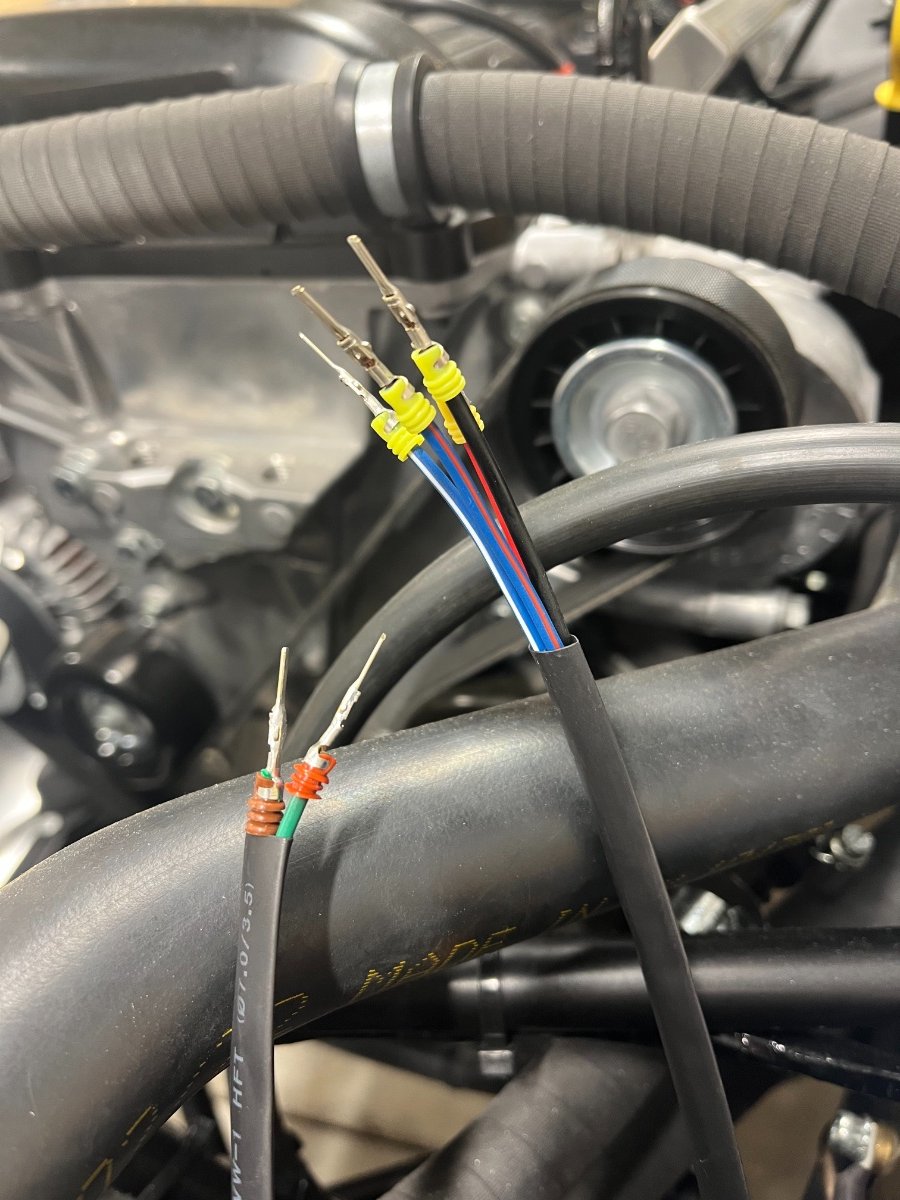
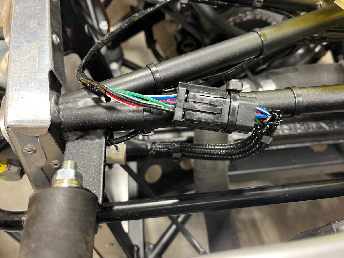
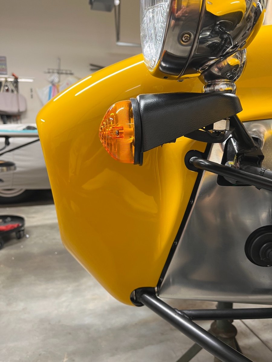
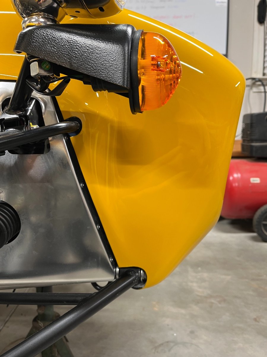
This post is out of sequence -- part of the posting backlog of tasks completed before start-up. Headlights and front turn signals Unfortunately, in the heat of the battle, I did not take pics of some key assembly steps and I apologize for that. I know text alone is not the best way to communicate this kind of stuff. The headlight and the turn signal "pod" share a hollow vertical stem that passes through the headlight stay and routes the wires through it. To install the turn signal you first remove the lens, attach the base to the "pod" (a black plastic shell) and then reassemble the lens. The pod mounts on the headlight stay under the headlight. To install the headlight you first need to disassemble the reflector/glass unit from the housing, including disconnecting the clip holding the headlight bulb housing and pulling out the running light bulb housing. I then installed the headlamp loosely on its stay on top of the turn signal pod, and threaded the ground wire from the turn signal pod through the hollow stem of the headlight into its housing and added it under the headlight ground screw. Next pic: Disassembled headlight and pod loosely on stay, with the turn signal ground threaded up into the headlight housing. Next steps are tighten the turn signal ground ring to the headlight housing, install the bulb housings back into the reflector/glass unit and attach it to the housing. Next I reconnected the bulb housings with their bulbs to the reflector/glass unit, threaded the bundle of 4 wires down the stem and reassembled the reflector/glass unit to the housing. Then I threaded the bundle of 4 wires from the headlamp and the positive wire from the turn signal pod through the hole in the headlight stay and into the chassis. Finally I tightened the single large mounting nut under the pod. This nut gets loosened for aim adjustment. Alignment of the headlights and pods on the stem is "infinite" -- it is up to the builder to align the pods straight, and to use headlight aiming equipment to fix the headlight horizontal and vertical angles. The counter torque to the above mounting nut is your hand holding the headlight, and maybe your knees holding the pod from turning... The electrical connection of the front lights to the chassis loom is made with a 6 spade "Econoseal" connector per side which you need to put together. Each Econoseal connector combines 4 leads from the headlight (low, high, running and ground) and 1 each from the pod and wing repeater (turn signal positive wires). Easier to assemble than I expected. The 2 spades in the sub-loom on the left are the turn signal wires. The insulating sleeves are not in their final position. Secured the repeater wires with zip ties under the front tubes of the upper wishbones leaving sufficient loose length outboard to accommodate steering. Next I added 1/2"" braided sleeve to the last ~6-8"" of the bundles near the connector (the edges look fraying but they are melted). Finally I routed the lighting loom inside the chassis and connected and secured the assembled Econoseal connectors to the top chassis tubes. Proper loom routing and securing is a key ingredient of the front lighting installation. It is critical to first properly route and secure the repeater wire along the wishbone to keep it out of the way of things, yet allow enough slack for steering. Only then you can finalize the routing and securing of the rest of the wires. Cheers!
-
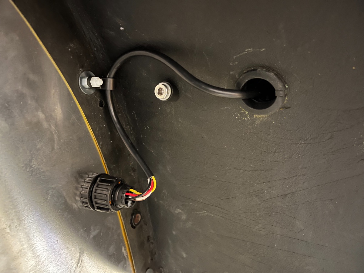
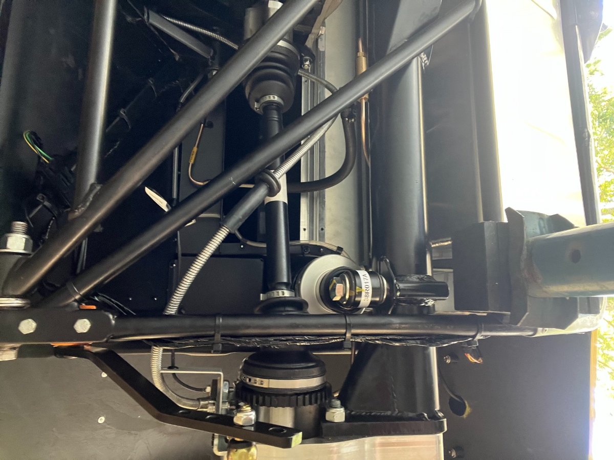
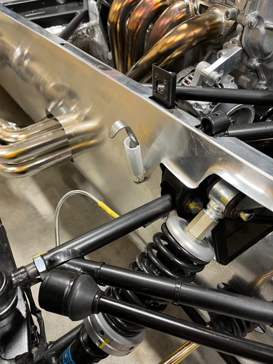
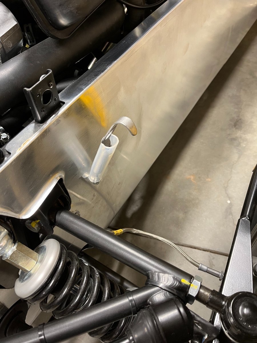
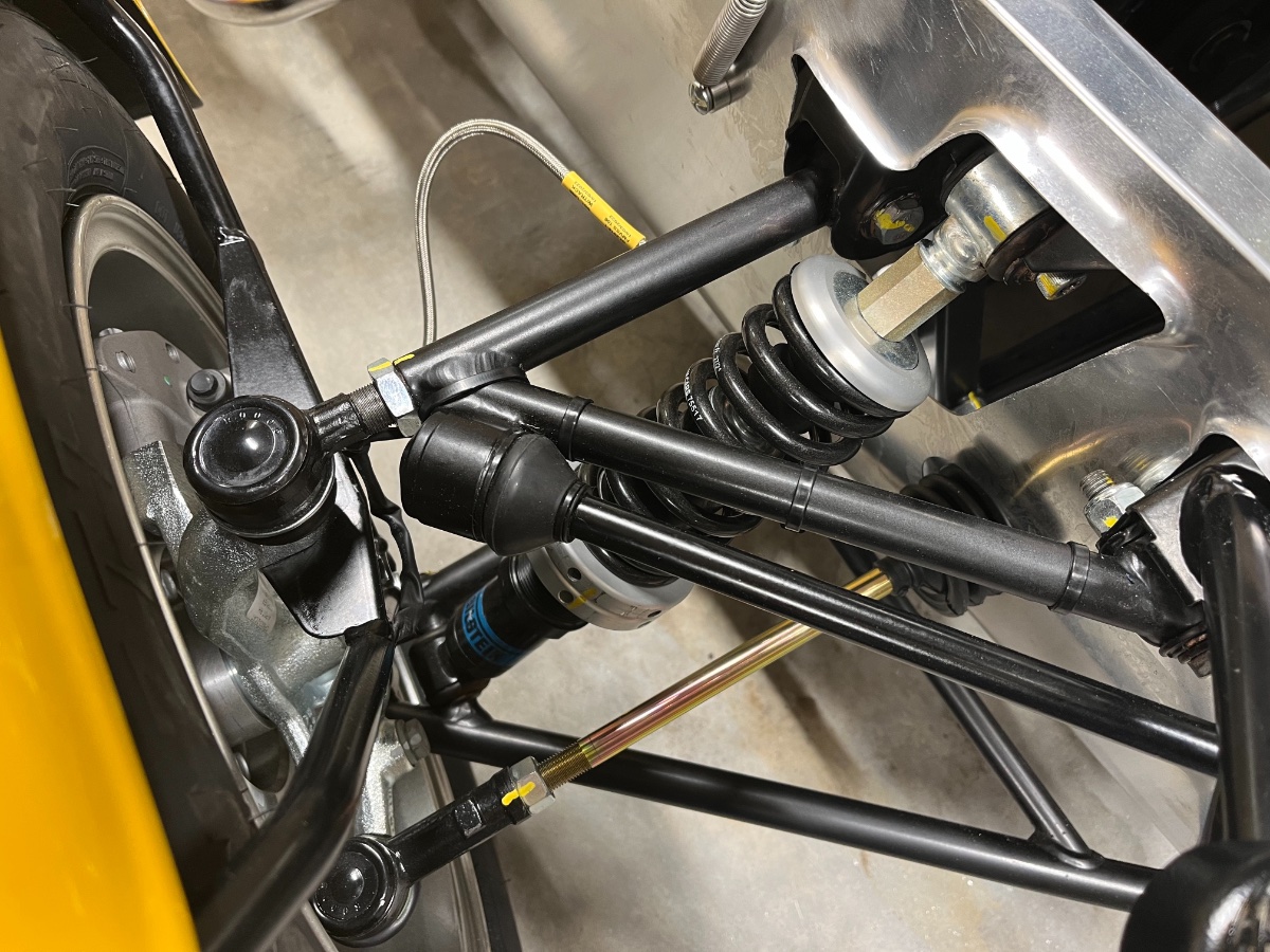
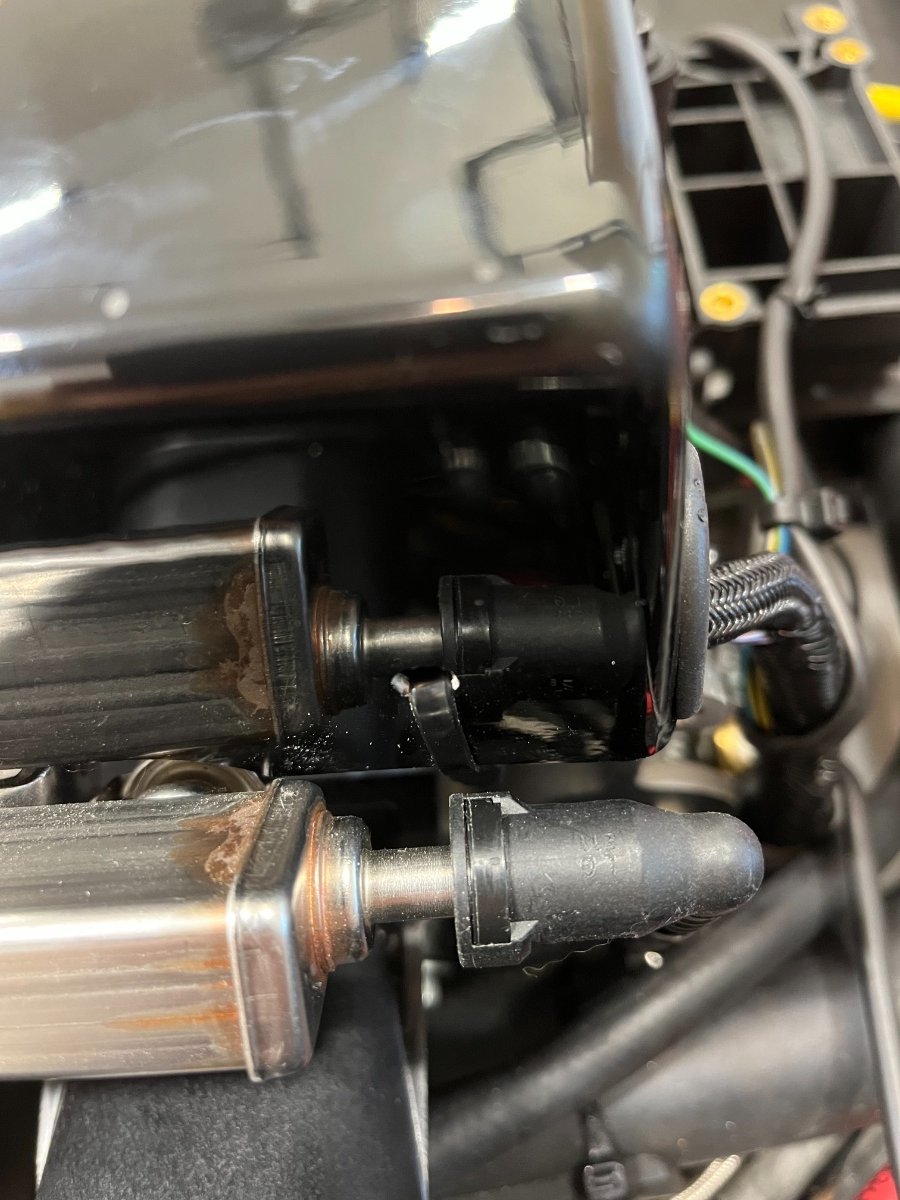
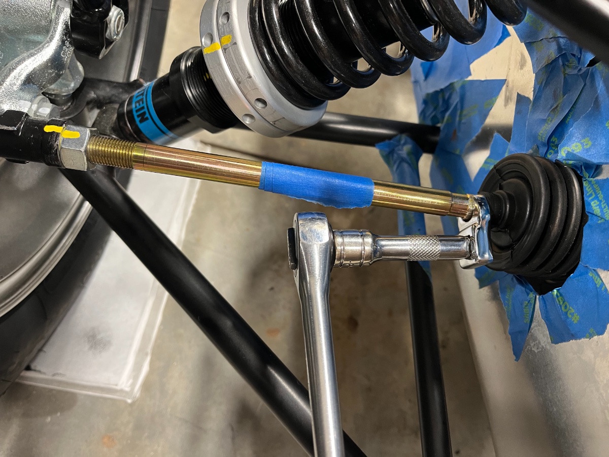
Small fixes after first drive Speedometer not working My first suspect was the gap between the sensor and tone ring being too big. I removed the sensor from the bracket (which also serves as the sta-bar link attachment). The range adjustment of the sensor was already at minimum, so the only option was to bend the bracket. I decided to do this in situ with a long woodworking clamp running underneath the wheel hub and reacting on the rear side of the deDion tube (over a piece of wood). I had the rear of the car on jack stands so once I got some bend in the bracket and reassembled the sensor I started the car, put it in 3rd and let the clutch out. The speedo sprang to life. Coil cover touching bonnet The coil cover is held by 2 screws on the RH side and tends to lift up on the LH side. Due to the shape of the cover and small witness marks on it the risk of bonnet contact seems worse at the rear. I drilled a small hole on the LH vertical side of the cover about 1" up and forward from the corner, and snuck a zip tie through it and through one of two small holes in the valve cover. The zip tie and hole are visible in the following pic right above the fuel connector. If this fix does not eliminate the rattle we were hearing I will simply remove the coil cover and add lightness instead. Next items to address are TPS and idle calibration, and dipstick "calibration" which will most likely involve cutting a TBD length off the bottom of the dipstick guiding hose. I also started preparations for titling and registering the car in SC. I will devote a beautiful post just to that, once we get there... Cheers!
-
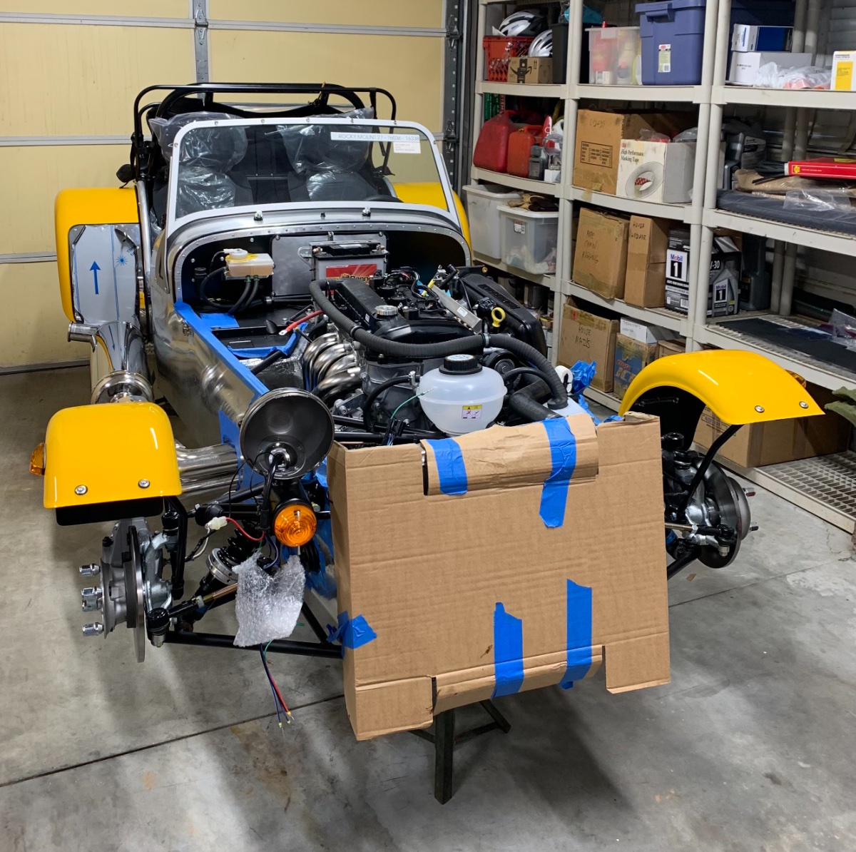
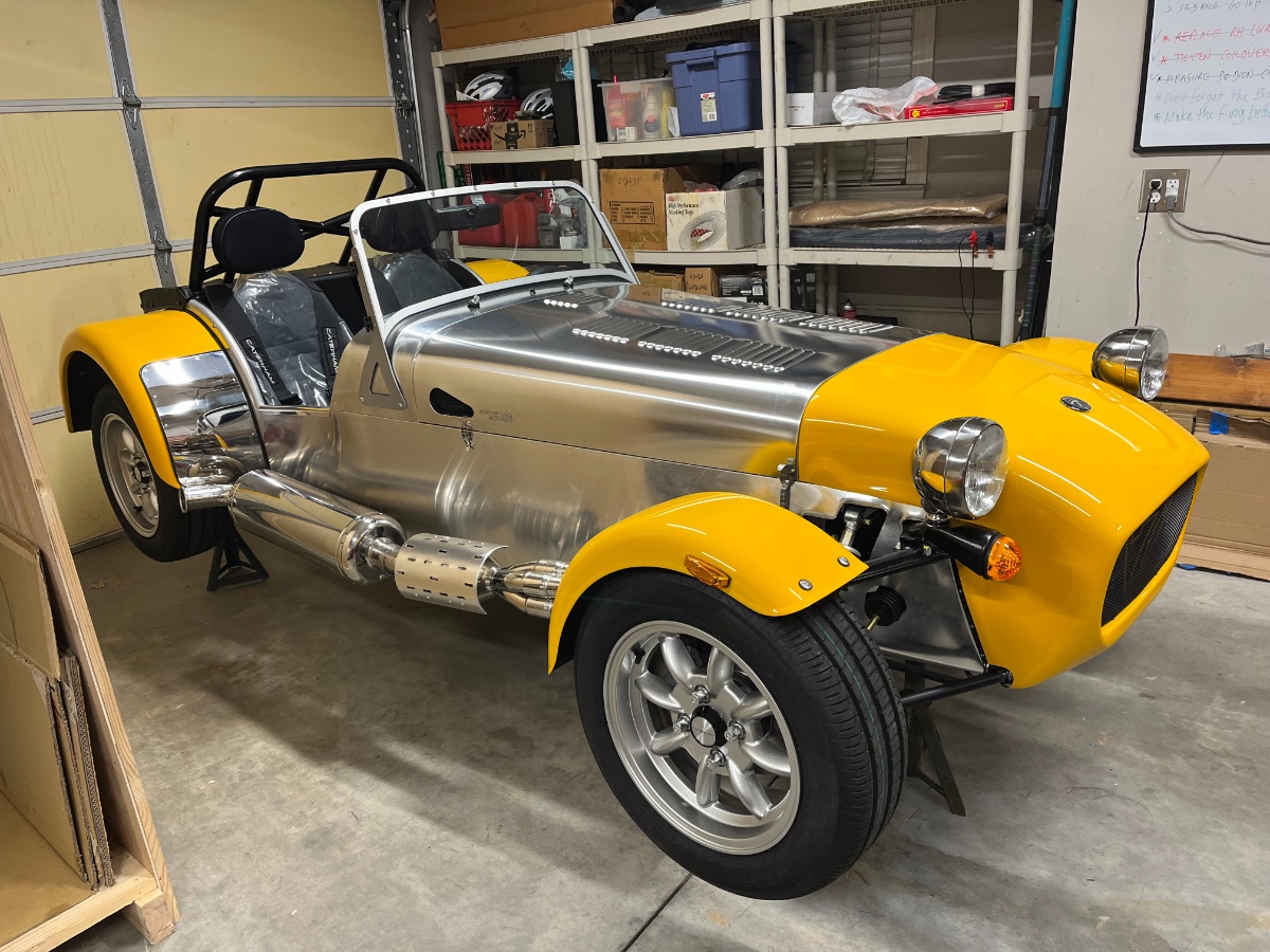
Maiden Drive! My wife and I went out today (Tuesday, 3rd of Oct) for our maiden drive! Drove a leisurely 2-3 miles or so around our neighborhood, got accolades from some school kids… It was awesome!!! We were both grinning the whole time like idiots. Got once into 3d gear for a short distance… Key points from the drive itself: - throttle response is not bad but then again I barely used any... I know I need to calibrate the TPS and idle - brakes are heavy as expected (not bedded in and no booster) - steering is delightful - clutch is almost on/off. Will get used to it. Disengages and engages fine. - shifting is great - oil pressure perfect - coolant temp quite high - leveled off pretty quickly at ~100C; granted we were driving very slowly - no speedo response. I know this is quite common and traceable usually to either the gap between the sensor and gear, or a bad ground. Will chase this tomorrow. - no unusual noises except what seems to be the coil cover occasionally touching the bonnet — it lifts up some on the no screws side. I’m envisioning a small custom hole and a zip tie clamping it to the loom, or just leave the dang thing off. An underperforming component should not get a free ride. Sir Colin would likely not have one to begin with. - my wife loved being in charge of canceling the turn signal... After the drive: - oil level barely registering on the dipstick, hot or cold. I know I have the specified 4.75 quarts in the system. You can see a trace of oil at the very bottom, below the flat area. I suspect the dipstick hose is too long (or there was an undocumented change in sump capacity...) - coolant level started near max mark before the drive and ended up after the drive at bottom of the expansion tank. I guess more air being purged. When it cooled down I filled it to the min mark, started it and let it idle for about 10 min. The level did not drop again. When it cooled down again I filled it to near the max mark. - no leaks of any kind Will be chasing next the oil and coolant level issues and the idle and TPS calibration. Our neighbor took a short iPhone video in our cul de sac; I'll see if I can have the hi-res version posted on Dropbox or such and include a link. The pic below is a stop-gap from before I dropped the car on its wheels. It does show the bonnet on for the first time... Cheers!
-
Thanks, Graham. Found some on Amazon too, cheaper yet (with Prime free shipping).
-
Nose Cone My plan for today was to install the nose cone and bonnet, get the car on the ground and go for a short and leisurely Sunday afternoon drive around the neighborhood. I thought the car did not need to be driven before looking "complete". A matter of decorum.... Well, our maiden drive is delayed because I got in a fight with the nose cone and it consumed several hours of Dremeling out the anti-roll bar and lower wishbone clearances and trying to line up and engage the four diabolical "screws". They have cute coin turn slots but no way I can engage one with a coin between my fingers... ended up using a stubby flat screwdriver. A satanical concept this fastening method. Eventually I won that fight and got all four engaged and all suspension clearances good. But I lost the one against the self adhesive foam strip that goes across the back of the nose cone under the bonnet. There was no way I could peel the F-ing backing off the F-ing adhesive!! I got so pissed that I threw the damn thing in the trash and ordered some 1/2" wide x 1/8" thick high density black on Amazon, due to be here tomorrow. Once it arrives it will be time to futz with the bonnet. Hopefully with less drama. It's amazing how smooth and effortless the start up went compared to these dumb bits. OK, the nose cone is on, no scuffs, and I feel a little better now... Now expecting the maiden drive within the next couple of days. P.S., an upcoming post will cover the headlights and front turn signals. As you can see they have been installed (prior to the start up) and all work fine. Cheers!
-
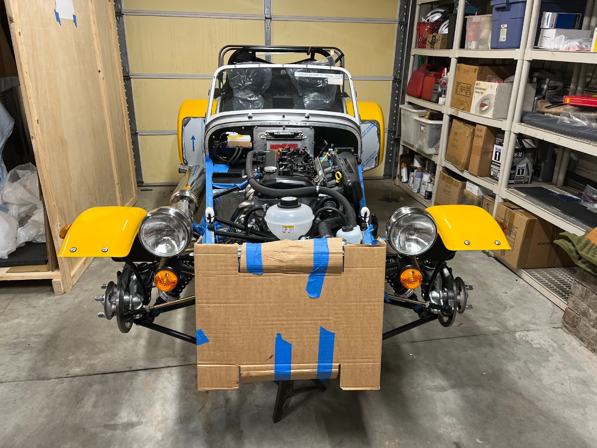
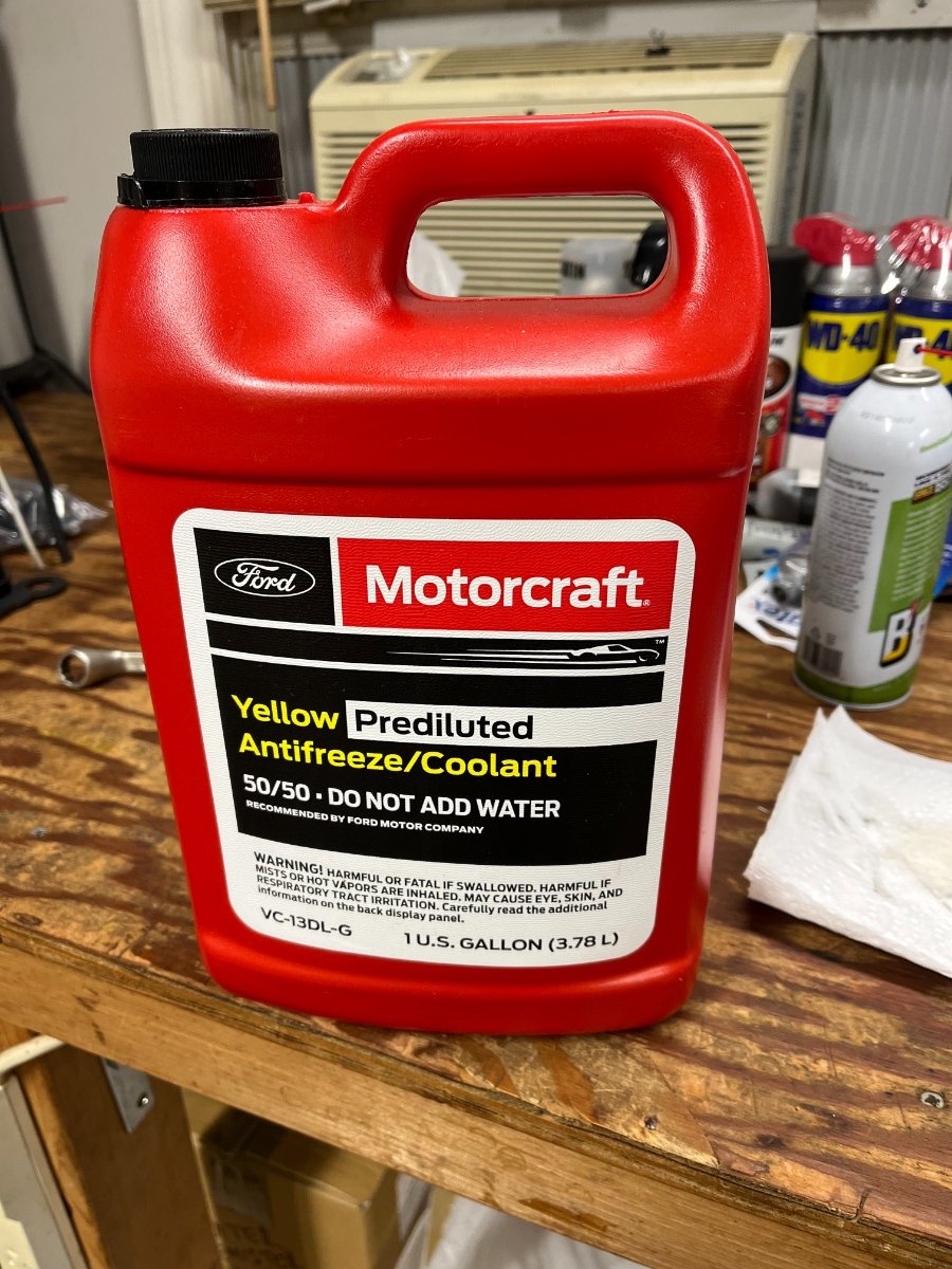
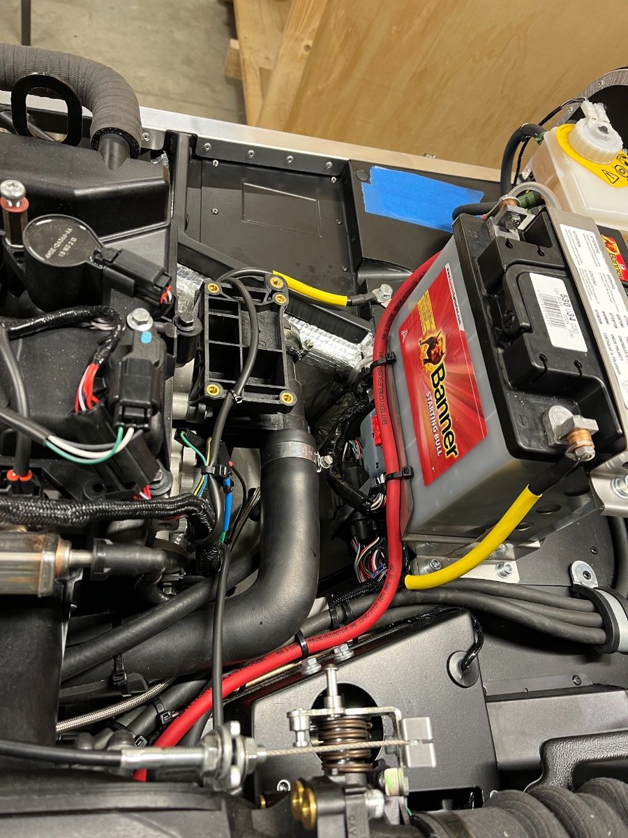
=== SPOILER ALERT === I am currently running about a week behind posting about progress in chronological order. However, today (Saturday 30th of September) I've reached a significant milestone, so I will jump right into it and postpone reporting prior progress for a bit later. Prep for Start Up Tried to charge the battery with the trickle charger but it wouldn't charge. Josh Robbins pointed out that it is delivered dry and needs acid fill. Duh... Bought 2 quarts at NAPA, removed the battery from the car, filled it up (took near 2 quarts) and set to charge at 6A. Filled engine oil -- 5 quarts + 600cc = 5.3L Mobil 1 5W50. Raised the front jack stand height by ~1"" to slope the car back a bit to help coolant fill. Tightened all hose clamps and loosened radiator fill plug. Filled coolant (no heater) -- 4.5L Motorcraft Yellow prediluted. ""Pumped"" the main coolant hoses (squeezing by hand) and watched air bubbles out into the expansion tank. Installed the fully charged battery -- 12.73V. Filled 5 gal of QuikTrip 93 Octane "Top Tier" gasoline from brand new container. Mounted the wheels to signal the car that we're serious, but left it on the jack stands in case need to access hoses or wires or look for leak sources underneath. Connected the battery terminals. All kinds of lights and dials came on! Took a little while to figure out what are all the On vs. Off positions and turned everything off. But so far everything seems to work! Connected the fuel line. Start Up!! Turned the ignition on for ~5 secs and turned off; repeated maybe 30 times to prime the fuel line. Pulled the inertia switch connector off as well as the spark plug connectors -- realized that should have cranked the engine first to lubricate it before priming the fuel line, so wanted to avoid any risk of unwanted ignition. Proceeded tp crank the engine for the first time (with no fuel). Love that red button!! Kept cranking for close to a minute - it cranked strong and built oil pressure up to near the 3 Bar mark. Reconnected the inertia switch and pressed its top button. Drum roll.... Pressed the start button and the engine kicked in immediately and settled right away into a reasonably smooth ~600 RPM idle, as if I just shut it off after a trip!! No sputtering, no hesitation, no shut down. Surprisingly civilized sound level and smoother idle than I expected! Strong oil pressure and gradual rise in temp, as expected. Video accessible at the enclosed link (I hope it works... please let me know if not) shows that actual very first start up. https://www.dropbox.com/scl/fi/q5jh0a9p557abp9fqmzt5/IMG_0375.MOV?rlkey=y3gub64k1zt7ncjyqbpnjcwrm&dl=0 Note gauges: This was truly a flawless start up! I let it run for less than 1 minute and turned it off. Oil level was at bottom of dipstick and water level was near bottom of expansion tank. No leaks anywhere. Topped both up and restarted. Ran it for another ~1 minute, stopped and topped up the coolant and oil again. Restarted and let it run for a few minutes until the radiator fan kicked in and out a couple of times and then I turned it off. No further topping was needed and again no leaks. Never touched the throttle. Ended up filling in total 5.7L oil and 5.3L coolant. * * OCT 5th EDIT: Oil: After consultation with Josh Robbins I drained 1.25 quarts for a final fill capacity of 4.75 quarts (4.5L). My dipstick calibration is judged wrong based on known fill specification and my actual fill. I will be adjusting the calibration by shortening the dipstick guide hose. Coolant: Ended up adding coolant after the maiden drive (see a couple posts down). Final fill quantity at time of this writing is 7 quarts (6.6L). Tomorrow I will drop it on its wheels, torque them to 63 ft-lb (left the torque wrench on the driver's seat...) and take it out for its maiden little drive around the neighborhood! It's a beautiful thing!! Big Cheers!
-
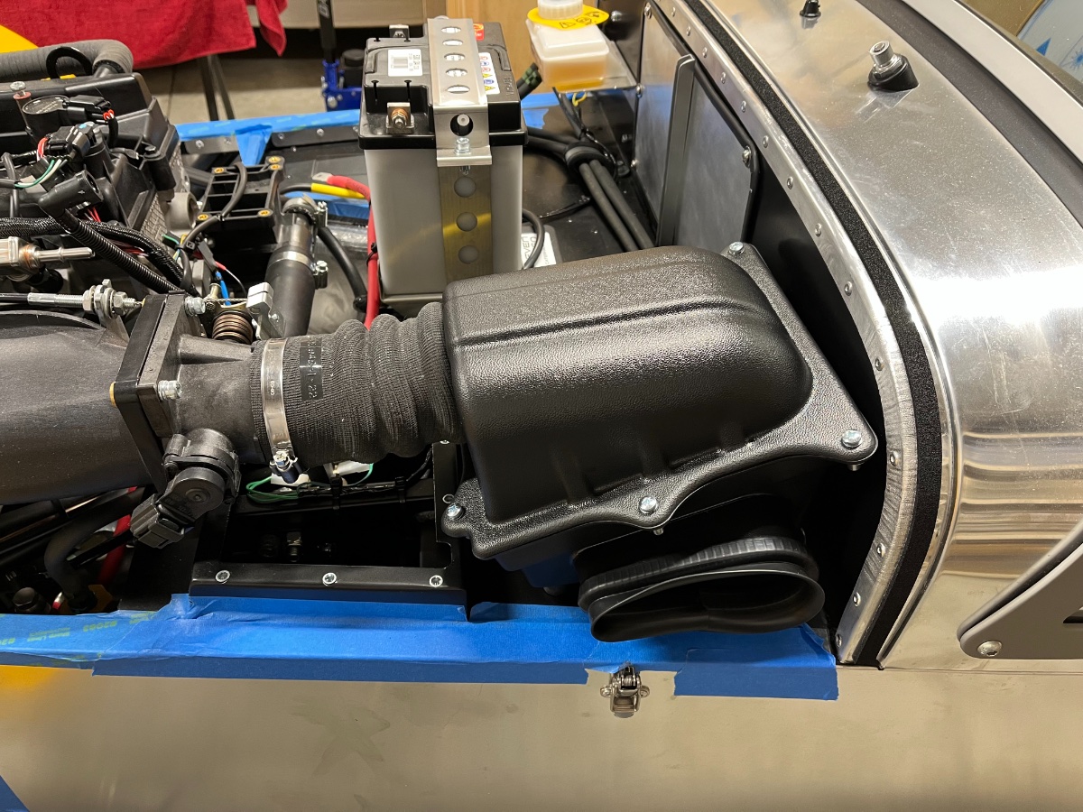
Air box Installed the intake seal on the bottom part of the air box, with the ends at middle bottom of the intake. This job was a bitch! Installed the air box with the air filter on the car. Used 3 wide washers inside the box under the nuts (same parts as for the rear wings to body connections). Left the pedal box covers off for pedal stop adjustments after start-up.
-
John, thank you. As you can see in my last pic, drilling out one of the existing floor rivets would be quite a detour/bend back and I don't want to drill out any skin rivets. In general I don't like the idea of drilling out rivets in rails/tubes as the back bit remains in the tube. I realize you don't hear it rattling about over the general racket of a Seven but still... I will be watching the loom over time and see... Cheers!
-
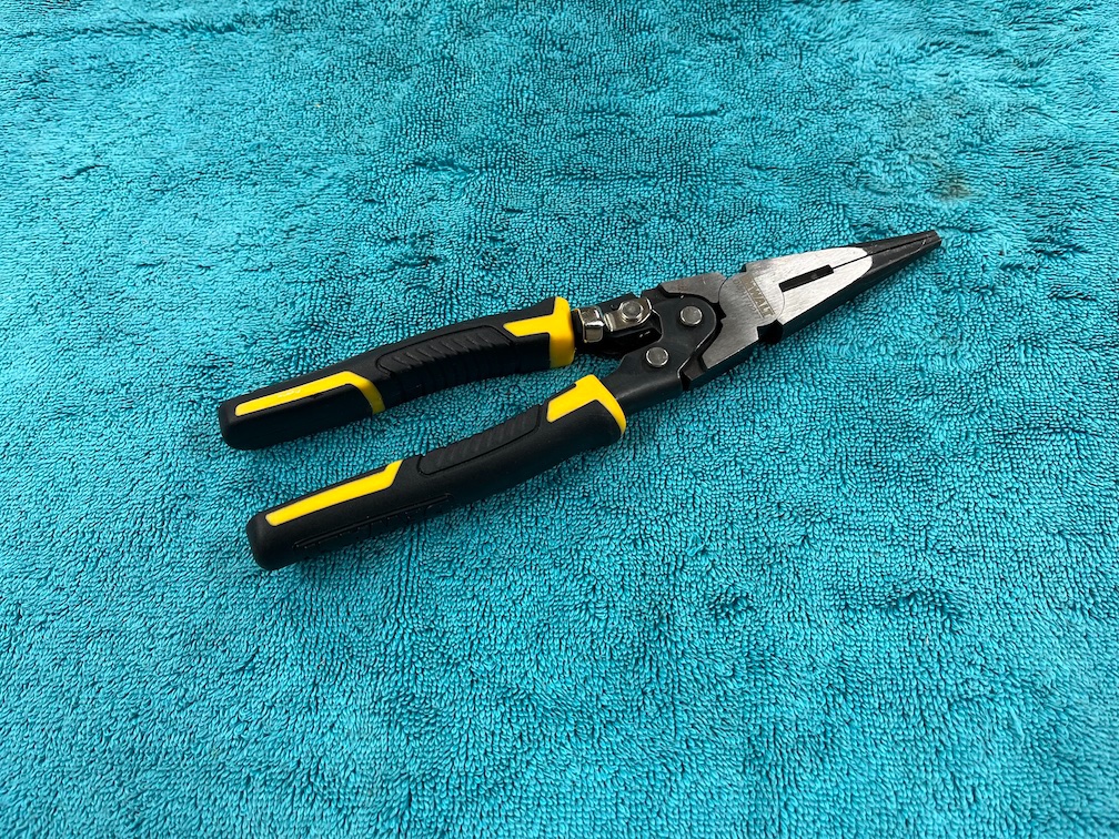
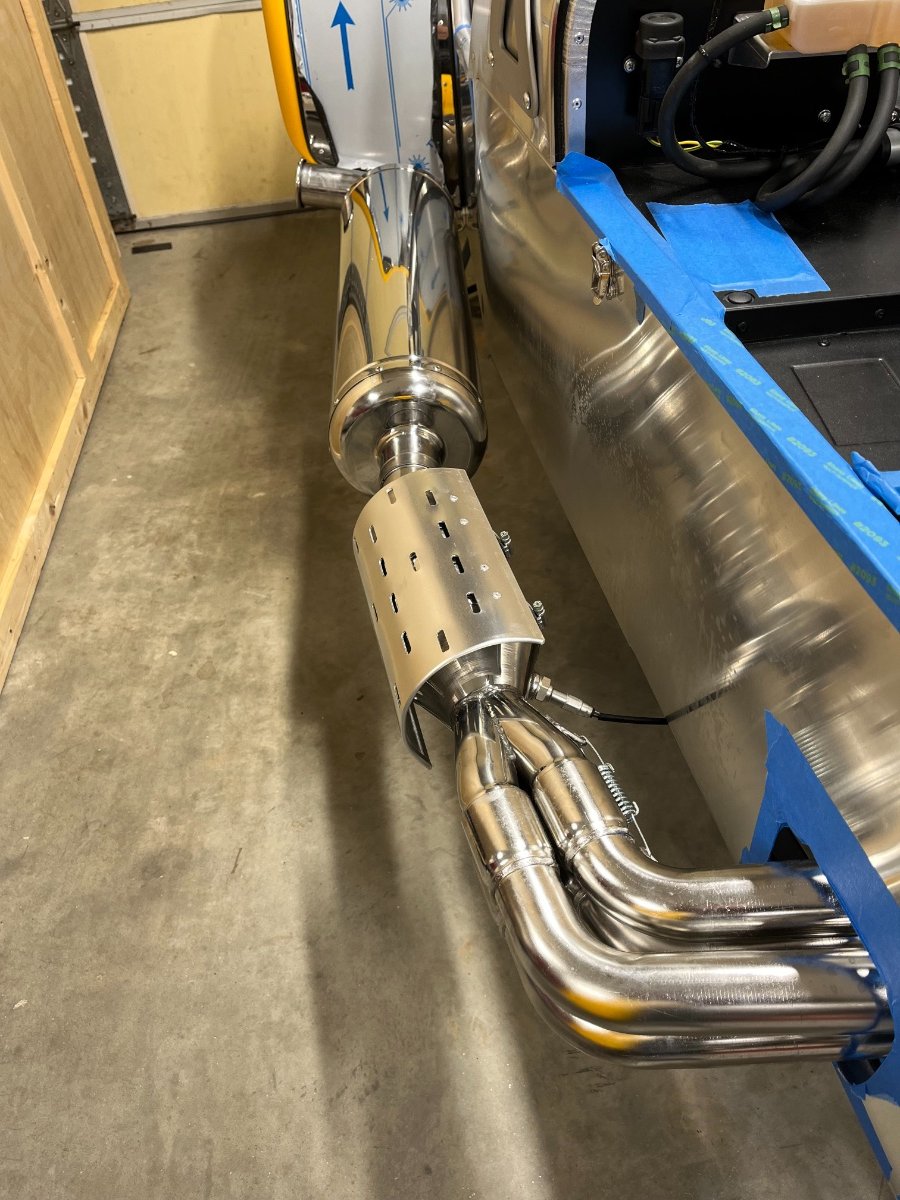
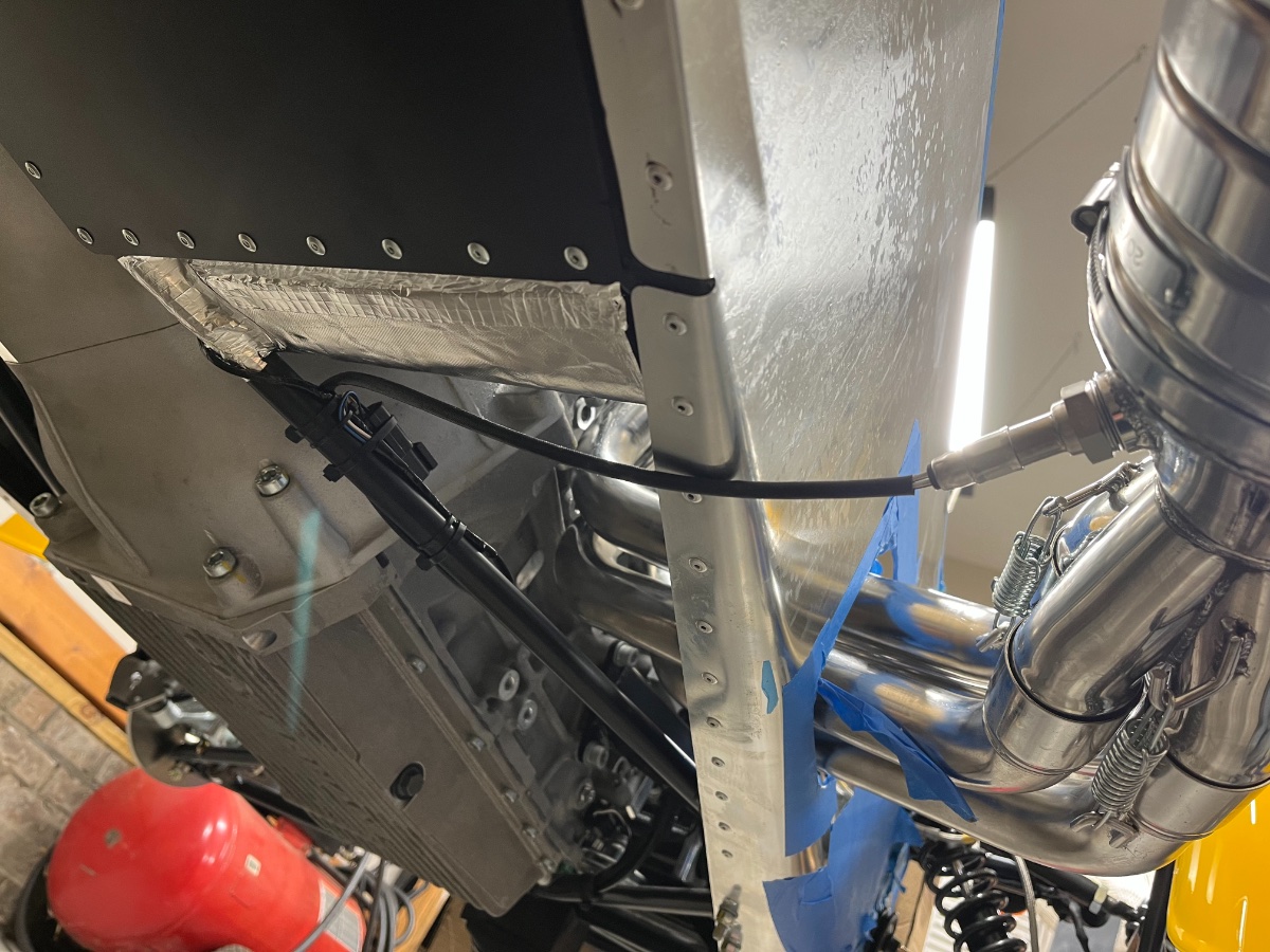
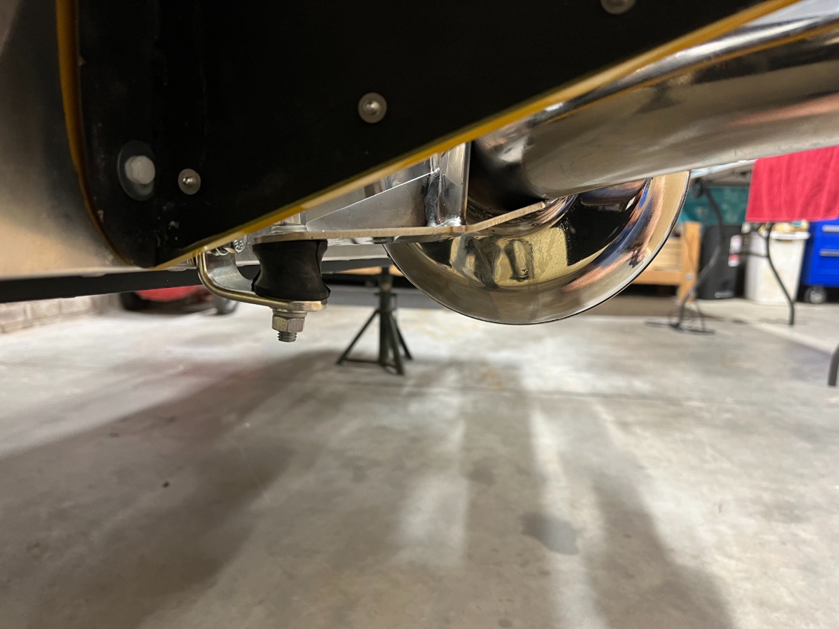
Exhaust Exhaust installation was pretty straightforward with the following details worth noting: - hooking up the two springs connecting the primary exhaust pipes to the collector/cat takes some effort - installing the muffler is better done prior to installing the RH rear wing - muffler ground clearance is a concern in a Seven (I tried to maximize it) - there is no good way I know of to secure the Lambda sensor loom to the footwell Here are the steps I took: 1. Installed collector/cat on the primaries. Compressed the connecting springs as much as possible with 4 zip-ties each and used pointed toggle pliers to force them over the hooks. 2. Once the collector/cat was installed, torqued the primaries to the head. 3. Installed the muffler rear bracket and isolator on the chassis near the rear wing. 4. Installed the muffler. Need to exercise care not to scuff the wing while maneuvering the muffler into the cat outlet pipe. It may be safer to install the RH wing after installing the muffler. 5. Rotated the muffler on the cat outlet pipe so as to maximize ground clearance (within reason -- outlet pipe is rotating up as you do this) and tightened the clamp. Rear bracket and isolator: 6. Installed the cat heatshield and the Lambda sensor. 7. Secured the Lambda sensor loom and connector to the chassis diagonal. Decided not to attach the loom to the outer chassis rail or the footwell so as not to damage the footwell heatshield covering. I suspect I will get some feedback on this one. Next (very brief) post: The counterpart: Intake (airbox). Cheers!
-
Bill, thank you for the kind words. Indeed, I didn't think that one was functionally needed (and none included or even shown in any of the guides). The wire loom has a sleeve, is secured close to the hole on both sides, and the hole is in fiberglass. However, I will make it a point to try to add one. The hole ID is 33mm and the connector OD is 32mm, so the grommet will need to be stretched over the connector after the connector was passed through the hole, and then the grommet would be installed. Hopefully Ace Hardware will come through... I will update the post once added. Cheers!
-
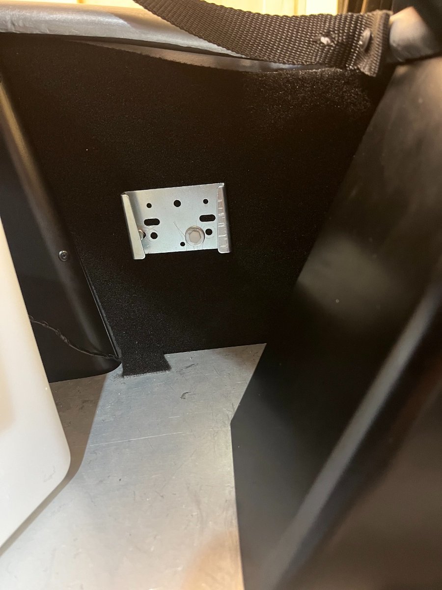
Water Bottle Bracket, Full filler Cover, Taillights These steps are a bit related to the rear wing installation so we will mention them here. Had to drill 2 "unplanned" new holes in the washer bottle bracket and one "planned" hole through the body skin to be able to fit the washer bottle between the boot lip and floor. Installed RH corner boot wall carpet piece under the washer bottle bracket and fuel filler cover. Installed taillights and secured each loom with a nylon clamp onto a nearby wing mounting nylon bolt. Cheers!
-
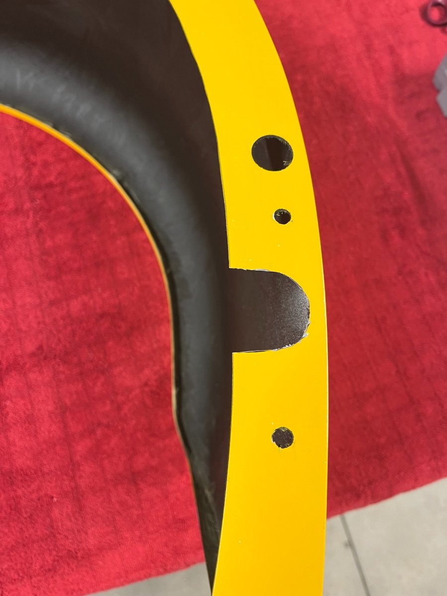
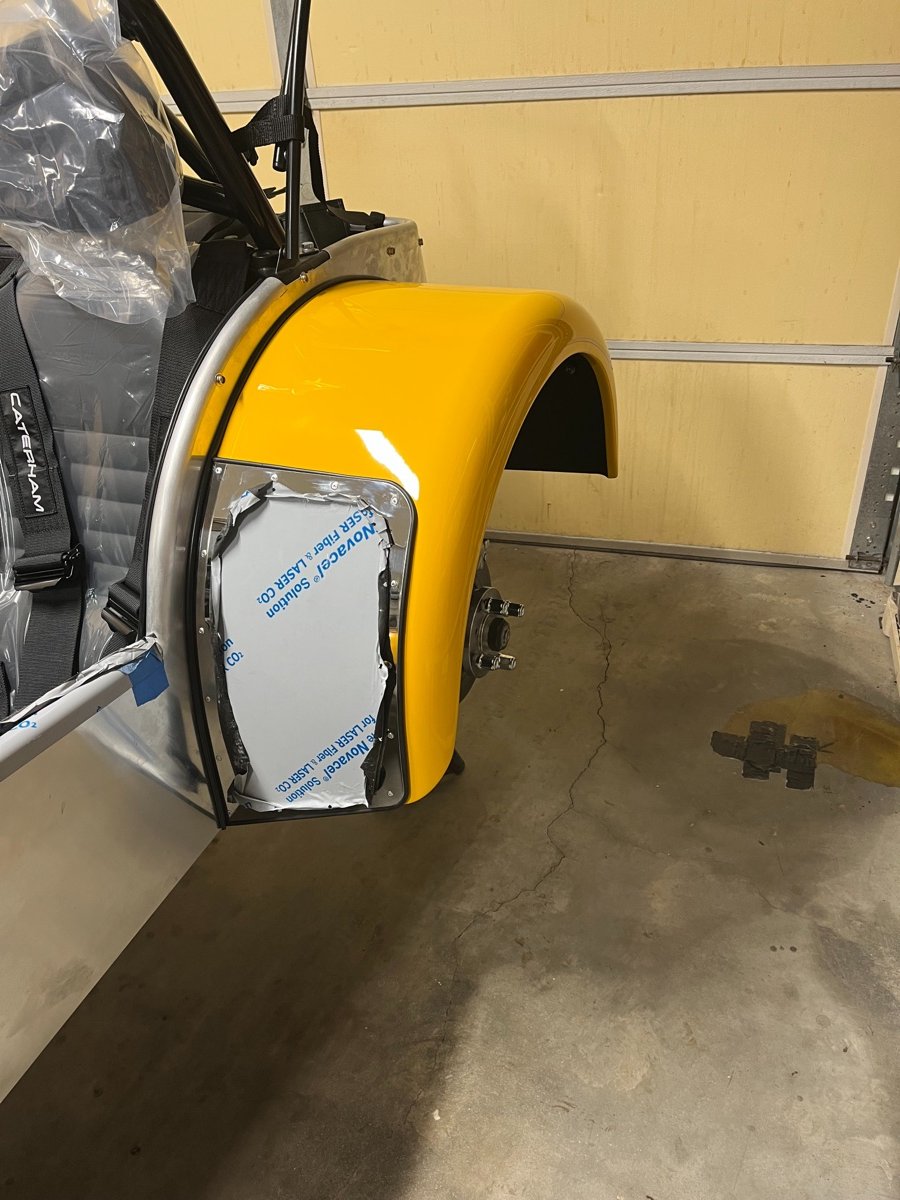
Rear Wings I have to admit that drilling and riveting the protectors to the wings was probably the hardest and most nerve wrecking part of the build. But here are the steps I followed to get the rear wings on the car: Planning: Reviewed protectors, piping and rivets. The kit does not include washers for the back side of the wing protector rivets but I decided they are needed. Assessed workable size of the washers. Washer ID should fit M3 bolt. OD constraint is the radius of the fiberglass ""fold"" along the body interface and the location of the holes in the protector along that edge. For the protector's inner edge to line up with the wing's, the washer OD should be up to 8mm. Ended up ordering from Grainger stainless steel washers M3 ID, 9mm OD, 0.8mm thick based on availability. Also, per advice in Chris Collins' blog, reinforced by Josh Robbins, ordered M5 plastic bolts and nuts for the body connection (from Bolt Depot). These provide a weak link protecting the body skin in case of a minor mishap with the wing. Decided to forgo protective films for the wings and nose cone. Wing prep: 1. Cut out the radius link slot with rotary Dremel tool. 2. Laid out and cut the piping for the wing protector and attached it to the underside of the protector with electrical tape. 3. Rivetted protector onto wing (see pic of installed wing further below). Several challenges: Need to ensure inboard edge of protector lines up with inboard edge of wing. Not easy, as you start at the inboard bottom corner and work your way up the inside trying to keep the alignment while overcoming the curvature of the wing. After 3 rivets up the inside egde started riveting along the bottom and outer edge to help hold the curvature. Ended up needing to sand off about 1-2mm of the protector edge towards the upper inside corner; used a Dremel Contour Sander. Pre-curving the protector does not seem practical since without rollers the risk is creating a visible fold in the protector. Chose to proceed without minimal pre-curving which creates a challenge to overcome the curvature with each successive rivet. Need to line up the piping to fit; used electrical tape underneath beforehand to help keep the piping generally near position. Difficult to place the washer on the underside when trying to insert the rivet while bending the protector. Ended up gluing one to the underside with superglue. On LH wing ended up with the protector inner upper edge protruding around 1mm beyond the wing. This would cause the upper part of the inner wing to not sit flush against the body and/or the protector edge to cut into the piping. Sanded the excess edge off with a Dremel linear sander. 4. Cut the body piping and attached to the wing with electrical tape. Wing installation: Installed wing on car with nylon bolts (and nuts in the rear holes) and the supplied wide washers. LH wing: One of the pre-drilled mounting holes lined up right at the trunk floor level, precluding inserting a bolt. Fixtured the wing temporarily to the body with bolts in 2 other locations and drilled a new hole from the inside through the aluminum skin and the fiberglass wing about 1" from the misaligned hole along the arc.
-
Indeed! As well as many opportunities for continuity issues, in the best British tradition... We will find out hopefully soon...
-
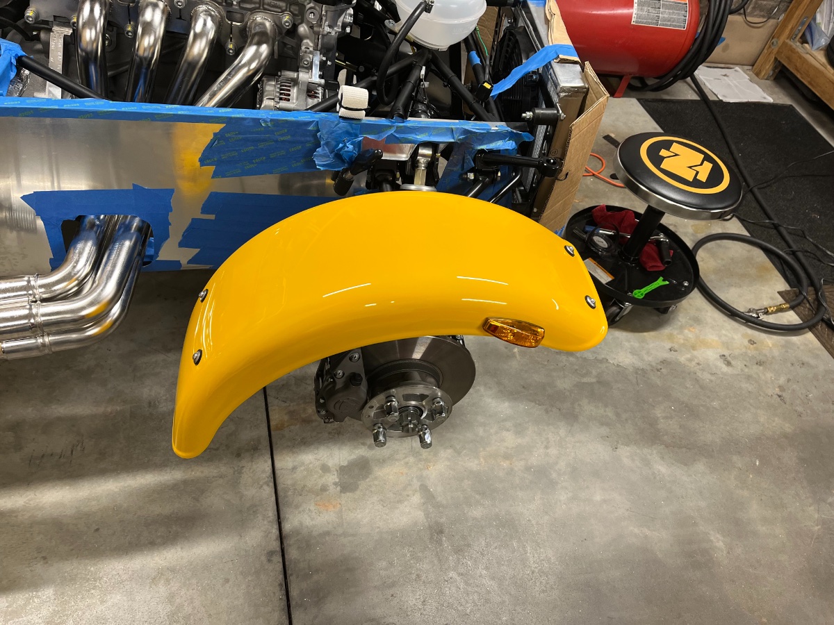
I found both front and rear wings to be tricky and quite nerve wrecking because of the many opportunities to mess up the finish or even the wing itself. Also, keeping the wings off improves access to other assembly and setup tasks and reduces the risk of accidental damage during the build. That's why I delayed them until as late in the process as possible. I have all four of them installed now with minimal blemishes (a sigh of relief) and will cover here the decisions and steps I took. This will be broken up into several posts based on pic file size limits. Will start with the fronts. Front Wings The front wings mount on tubular stays attached to the front wheel steering knuckles. The first decision required is whether to use fasteners per the 2015 text guide or adhesive per the IKEA guide. I considered first adhesive because it is the current direction and offers a cleaner look, and contacted several sources for information. After some learning and based on drawbacks in cost, surface prep, reliability and maintainability of the adhesive approach, I decided on mechanical connection of wings to stays with M5x0.8 stainless steel screws with low profile hex socket heads, neoprene and flat washers, and nyloc nuts. My goal for this solution is to provide a soft clamp over a relatively large area to reduce stress in the fiberglass, and still look decent. Wingstay Prep: Drilled holes for repeater light ground on underside near outer edge of each front stay. This proved premature on one side... more below. Bent each stay a bit to bring the horizontal lengths to be perpendicular to the wheel. Installed the wheels for reference. Used level with chassis cross beam as reference, water pipe for lever, and masking tape to protect the stays. Cut and inserted sections of silicone tube (16 mm ID) onto the horizontal lengths to serve as cushions for the wings. Cut out the front silicone tubes around the repeater ground holes. Marked the centerline of the tire on the silicon tubes to help ensure the wings and bolt holes will be centered vs. the wheels. Decided the locations of the holes considering the centerline mark on the stays, their horizontal segment lengths, and the width portion of the wing which can contact them -- centered about the centerline, 100mm apart on each stay. Drilled the stays (8 holes total) with the holes pointing toward the wheel axis. Wing Prep: As first step measured and marked the lateral centerline (symmetry line) on the underside of each wing. This centerline will need to coincide with the centerline marked on the stays. Installed the repeater lights to ensure nothing I do next interferes with them. Next decision is longitudinal positioning, or "clocking" of the wings on the stays. The IKEA guide suggests 80mm from front edge of wing to wingstay. I believe this is incorrect as it results in the wing being positioned too far down in front and too high in back, not offering enough splash protection and looking goofy. I chose 30mm from the leading edge to the stay. This position looks good and offers better splash control but is marginal for the repeater ground wire to reach the stay. Positioned each wing on the stays at the 30mm position while lining up the centerlines and secured to the stays with masking tape. Marked the front holes only through the stay holes from the underside -- centered laterally and 100mm apart. Removed the wing, drilled in it slightly oversized front holes from the underside, reinstalled and verified screws fit through. Realigned the wing and tightened on the front stay, marked rear holes on the wing again through the stay from the underside, then took the wing off and drilled from the underside. Reinstalled and ensured all 4 screws fit through. Repeater Wiring: The repeater light has 2 wires, a short ground wire which needs to be attached to the front stay with a sheet metal screw, and a positive wire which needs to be threaded through the front stay to emerge near the upper balljoint and be routed along the leading edge of the upper wishbone to inside the chassis. I found the proper sequence (in case you are using fasteners) to avoid redo's and frustration to be: 1. Have the wing loosely bolted onto both stays (4 screws). 2. Drill the grounding hole under the front stay such that there is room for the sheet metal screw, washer and ring connector near the outer washer and nut retaining the wing under the stay. This hole may need to be offset from vertical. Verify both screws - ground screw and wing screw - and related fasteners can coexist in the limited real estate under the stay. 3. Extend the ground wire to reach the grounding screw (I used ~3" of new wire with new ring connector and butt-crimp connector attaching to the cut existing wire). Do not tighten to the stay yet. 4. Remove the sheet metal screw and the wing attaching screws from the front stay, keep the rear ones on. 5. Thread the positive wire through the stay, to emerge through a hole near the hub. I did this by threading a bicycle brake cable in the opposite direction, light butt-soldering of the ends of cable and wire, and gently pulling and maneuvering the positive wire through the hole near the hub. Once through you will need to gently unsolder the "Econoseal" spade connector at the end of the positive wire to allow it to insert properly into its female counterpart on the chassis (see future post "Headlights etc."). 6. Once the positive wire is routed through the stay, connect the ground wire to the stay with the sheet metal screw (I also added a copper washer), taking care to avoid damaging the positive wire. 7. Insert back the wing securing front screws, again taking care to avoid pinching or scuffing the positive wire. Securing the positive wire to the front wishbone is best done after it has been bundled inside the chassis with the headlight and turn signal wires and inserted into the Econoseal connector (future post "Headlights etc."). Repeater positive wire being pulled out of the stay by soldered bicycle brake wire: Ground wire attached to stay: Wrap-up: Tightened the 4 wing-to-stay screws hand-tight, making sure the outer washers are centered relative to the screw heads. Cheers!
-
More Alignment Prep: Was initially a bit concerned about the accuracy of the digital level. The specs claim 0.1º resolution and 0.2º accuracy. Tested it first prior to performing actual alignment tweaks, and it seems to be repeatable within +/-0.1º which should be sufficient for our needs. The "Zero" function is very handy to establish a reference for subsequent relative angle measurement. Also measured the absolute lateral floor slope at the front and rear wheels with the digital level and the cross-car L profile to ensure no significant twist in the suspension. Got 0.2º in front and 0.3º in back, sloping in the same direction, which means a twist angle of 0.1º which is negligible. The alignment specs are: Toe-in: 20' +/- 10'. Camber: 2015 guide: -1º 20' +/- 15' ; Josh Robbins recommendation: -1.5º to -~1.75º There is no spec for castor and per Josh the standard configuration of 2 washers at each end of the lower wishbone rear bushing and 2 washers behind the front bushing is spot on and best left alone. Set my targets: Toe-in 20' (0.33º), Camber -1.5º (1º 30'). Since the steering arm is located vertically about mid-point between the lower and upper balljoint, adjusting camber will have major effect on toe, but adjusting toe will have minor effect on camber, so started with camber. Final prep step was to fill and load the water ballast to simulate curb weight in front, and to roll the car a few times before rolling it onto the "slip tiles". The following details may prove a bit tedious, especially if you are not too much into Trig, so feel free to skip.... Camber: Camber angle measurement is using the digital level, first on the cross car L profile to establish the horizontal reference and zero out the level, then on the uprights of the T-frames near the center of the wheel. Initial LH camber measured on target at 1.4-1.6º while RH measured 1.0-1.2º. ATAN of the ratio of upper balljoint thread pitch (1.0mm) over height between wishbone balljoints (220mm) yields 0.26º, which is the fixed step size in camber adjustment on a Se7en (one full revolution of the upper balljoint housing). Therefore increasing the RH camber by ~0.5º requires ~2mm (2 balljoint turns). Raised the front of the car on a jack stand and used my newly acquired balljoint separator to disconnect the RH upper balljoint. Turned it in 2 turns and reconnected. Have not found a way to torque the upper balljoint nut to spec but with the balljoint cone seat it has inherent torque retention. After dropping the front down on the wheels I rolled the car again back and forth a few times to let the suspension settle, vinyl tiles notwithstanding... Before confirming the final measurements I proceeded to tweak the T-frames for the positioning and locating of the nylon spacers and for their contact on the rim until I was confident I was getting repeatable readings. I also tested the camber readings by swapping the T-Frames side to side. The readings were within 0.1º. Finally, decided to verify the digital level reading by measuring the distance between the tips of the uprights and subtracting from the average (fore vs. aft) distance between the horizontal extrusions. 1/2 of this difference (20mm) divided by the height of the upright (800mm) equals 0.025, or ASIN of 1.43º. This compares pretty well with the 1.5º measured on each side by the digital level. Toe: Toe measurement was done by measuring the cross-car lengths between opposite tips of the horizontal extrusions, one measurement between the front tips and another between the rear tips. Half the difference between these two lengths divided by the horizontal extrusion length (800mm) equals the ASIN of the toe angle. The 0.33º target equals a length difference of 9.3mm. I used a right angle triangle to project, or transfer each tip of the horizontal extrusion onto the cross car L profile. A single measurement is required per test -- the distance between the marks on the L profile which is the length difference (pic below). Toe adjustment is done by rotating the inner tie rod while holding the outer tie rod end. The inner tie rod has wrench flats which are accessible after pulling its boot back (pic below). Initial toe reading showed substantial toe-out (more than 10mm length difference in the wrong direction). However due to the short steering arm the adjustment is quite touchy so it did not take many turns, but quite a few iterations, to reach the target. As I expected and hoped, there was no need to readjust the camber after adjusting toe; both sides stayed within 0.1º of their last settings. Steering Wheel Centering: After reaching the target toe setting, used visual comparison of the lateral gaps from the lines of sight along the horizontal extrusions and the rear wheels to center the steering wheel. The goal is to get the LH and RH gaps to look equal with the steering wheel centered -- the two pics below attempt to show that. Adjustment is done by turning the inner tie rods by the same small amounts (small fractions of a turn) in the same direction and verifying that the steering wheel does not drift from center. Final adjustment may still be needed based on driving. Alignment Results: I repeated the camber and toe measurements several times "from scratch" to verify repeatability. My final (for now) alignment settings are: Toe: 0.3º per side (9mm delta on L profile), steering wheel centered to the best of my method... Camber: LH -1.6º, RH -1.5º My front wheel alignment is done, and now I'm finally, truly, ready for the wings (to which I've been looking forward with some trepidation...). Hopefully the next posts will not take this long.... Cheers!