Yoram
-
Posts
257 -
Joined
Content Type
Profiles
Forums
Store
Articles
Gallery
Events
Library
Everything posted by Yoram
-
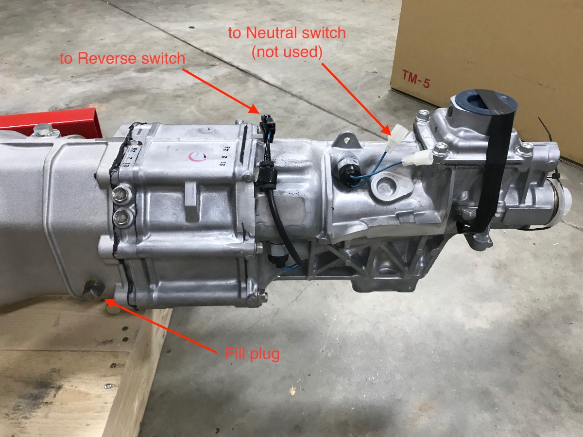
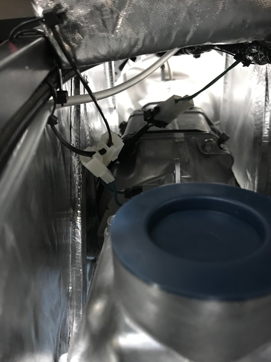
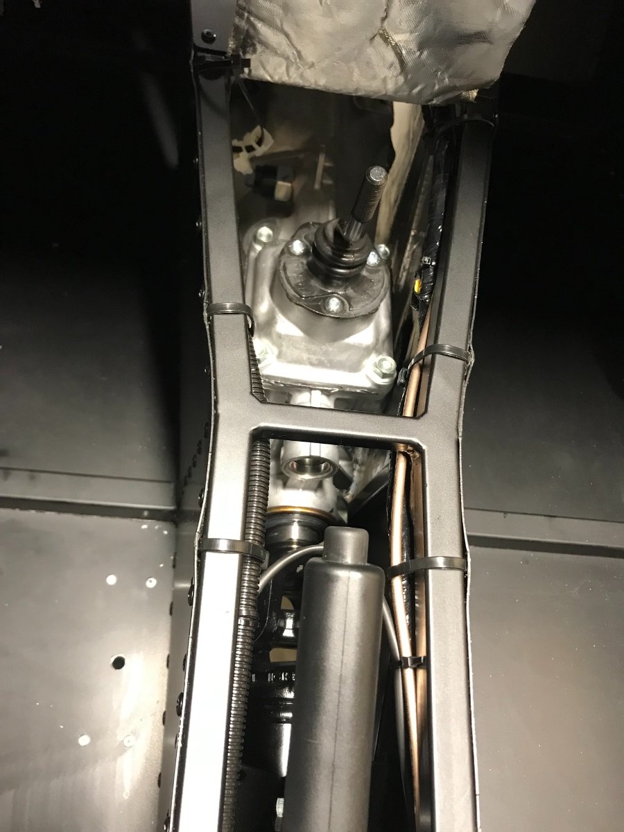
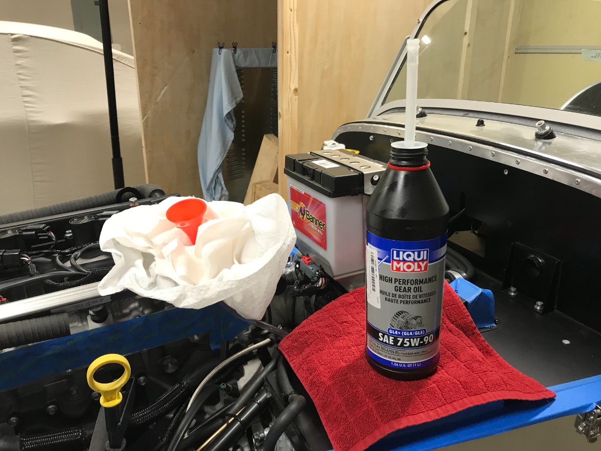
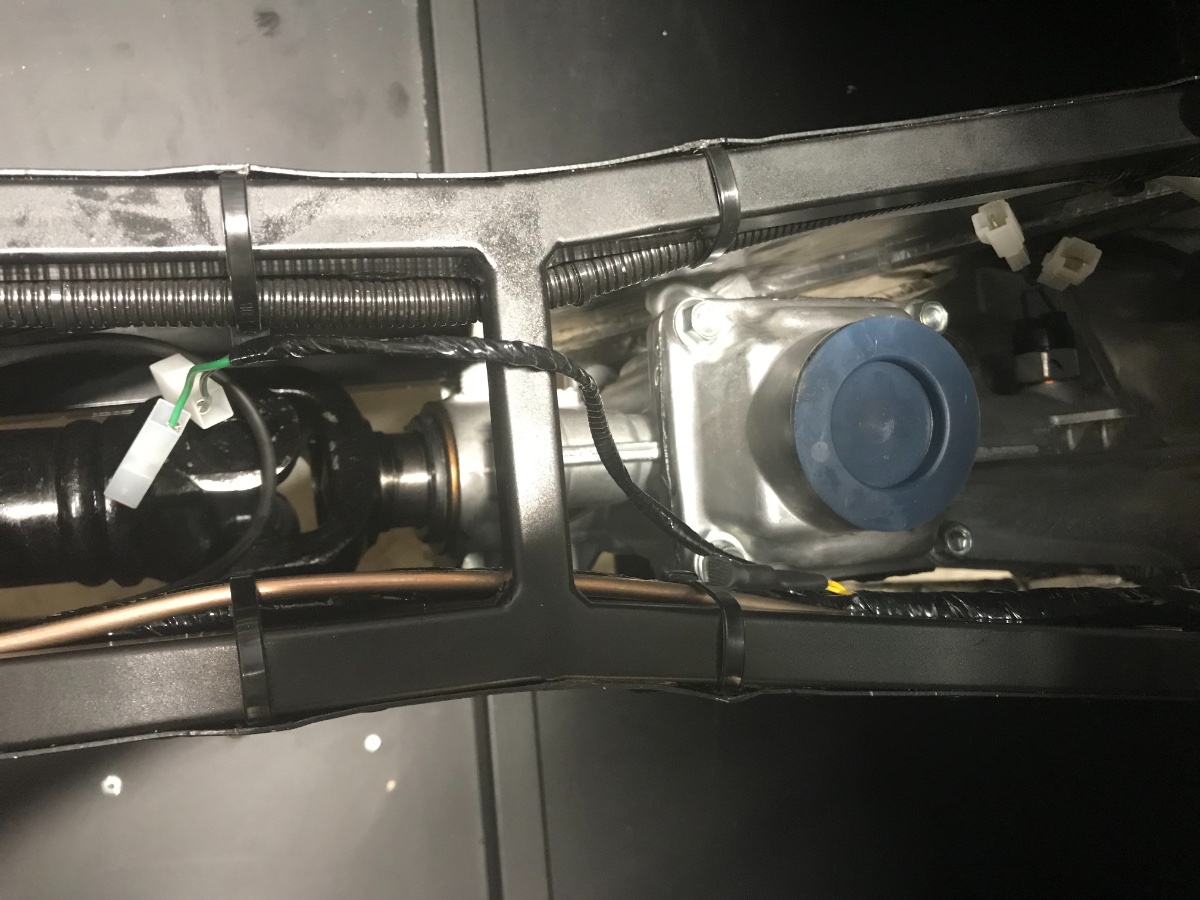
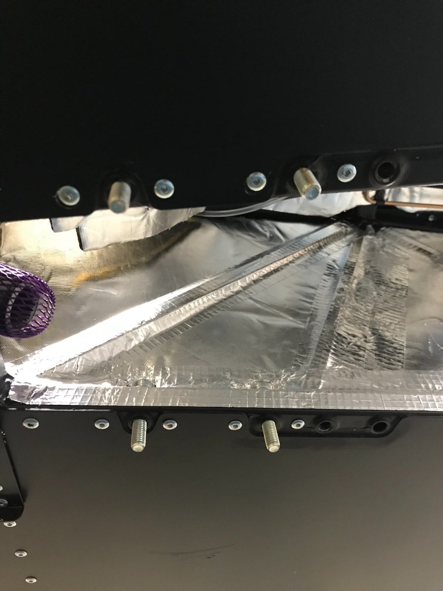
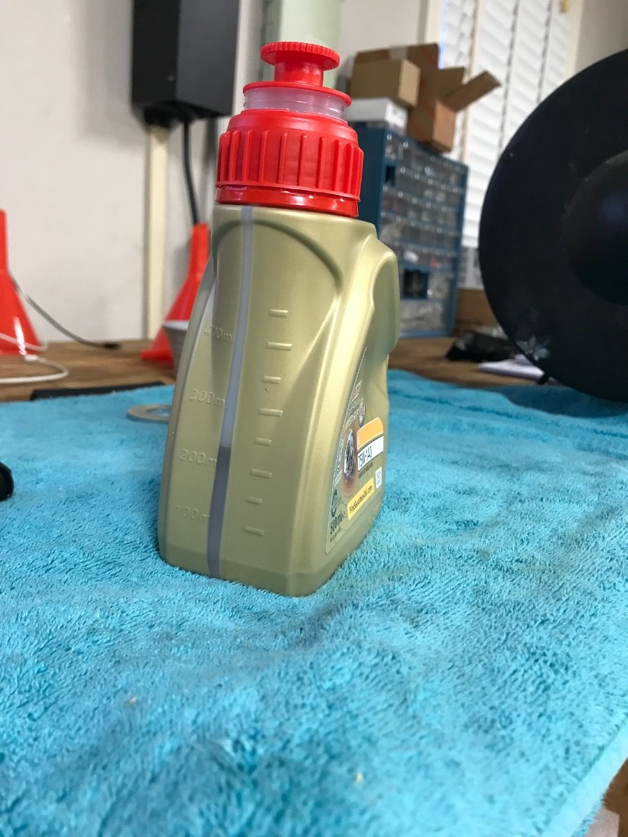
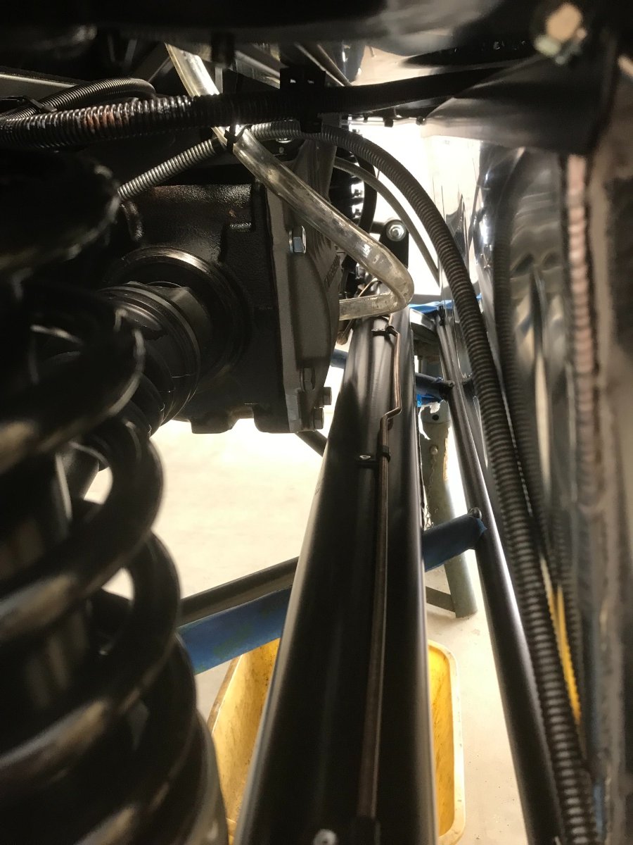
Gearbox "Clean-Up" This will cover gearbox wires, gearshift lever and topping off the oil level. For reference here is a pic of the gearbox with some annotations: Once the gearbox is in place a few tasks still are required to button things up: 1. Wires The Reverse switch connectors on the wires coming out of the gearbox need to be connected to the chassis harness in the tunnel. The connectors and wires need to be tied down and kept away from the potentially hot gearbox housing. The Neutral switch wires are not used on our cars but also need to be tied down and kept away from the gearbox housing. First task was to attach the Reverse switch wire connectors from the chassis and gearbox - quite an ordeal to do solo. Ended up inserting visegrips in open but locked position from the engine bay and then turning down the adjuster to gently hold the gearbox connectors in order to be able to grab them from the tunnel with one hand against the mating connector (if this makes any sense...). There is no room to insert two hands from the same end - this job is much easier with help, one hand from the cockpit and one from the engine bay. Secured the wires with zip-ties to the upper rail to make sure the connectors cannot touch the gearbox housing. Zip-tied the unused connectors of the Neutral switch to the upper rail. Neutral switch connectors held up by zip tie on left. Reverse switch connectors on right (and further forward), wires secured to RH rail. 2. Gear lever Once the wires were secured I installed the gear lever (without the knob yet!). Straightforward with 3 hex socket screws. 3. Oil top-off Topped off gearbox oil -- Liqui-Moly 75W-90 GL 4+. Access a bit tight - 14mm open spanner and index fingers of both hands to unscrew and screw back the plug. Used gravity feed with hose and funnel from engine bay. Used 3/8" OD hose and long tweezers to help it "make the turn" into the filler hole. Took just over 200 cc. Tightened fill plug by feel. Small hose coming down from little red funnel above. Cheers!

-
Congratulations! A few posts above you will find similar challenges re gearbox mount... Sounds like you had, uh, easier mating of the gearbox to the propshaft. I weighed the full and used bottle and calculated that I wasted over 6 oz. I would still top it off. In retrospect I think I would have installed the engine+gearbox first, then the propshaft and diff. The argument for doing it the way we both did is to be able to have a "rolling chassis" before the engine goes in to make it easier to roll the chassis on the wheels for the installation. As I described in one of my posts, I actually needed to do this but did not use the rear wheels - just the fronts with a floor jack under the diff. Could have had the jack under a chassis rear cross member without the diff or any of the rear axle in place. Anyhow, all is good... Likely the best source for Se7en build guidance is Chris Collins' blog: https://caterham420detailedbuildblog.co.uk/ I am referring to it quite a bit. Cheers.
-
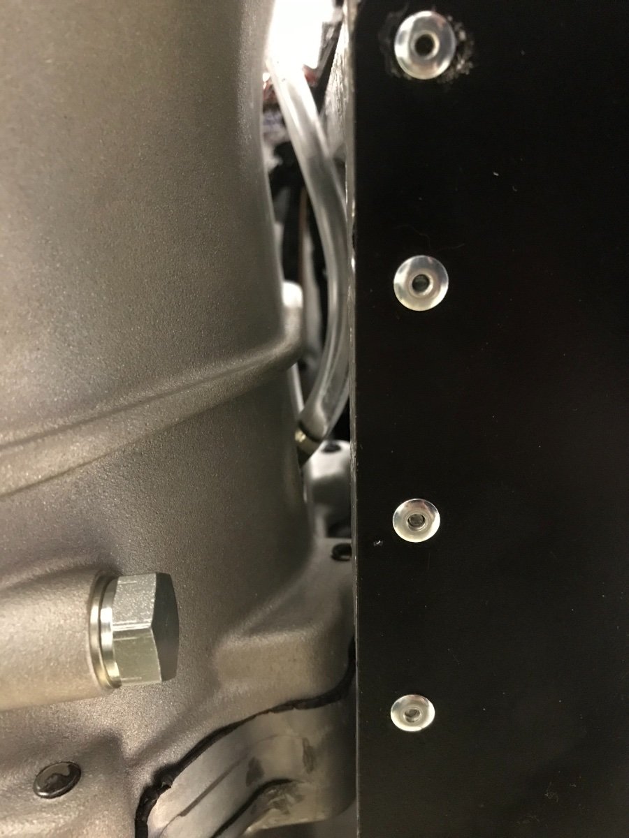
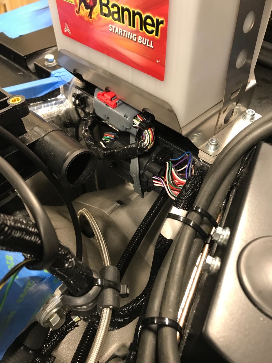
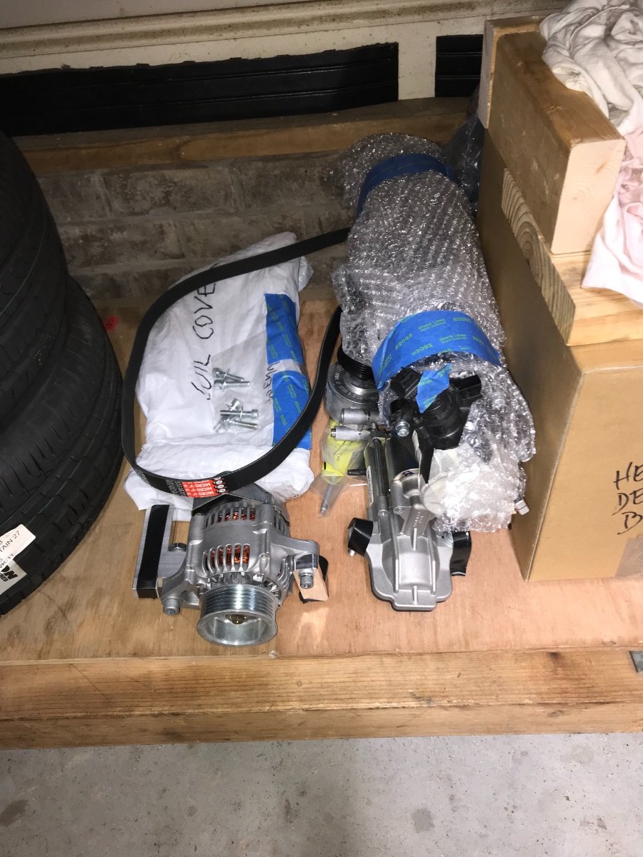
Again I'm incurring a lag between build sessions and posts but I keep an offline journal so we are not relying on my fading memory. This update will cover partial engine dress and wires and the clutch hose. Partial Engine Dress, Wires, Clutch Hose - Installed starter. Torqued bolts to 35 Nm per Chris Collins blog (could not find anything in either Caterham guide). Upper bolt impossible to torque from above with my tools. Ended up torquing from below with short extension and UJ adapter at hex bit. Attached 2 brown wires from chassis to big post already used for brown wire from engine. - Installed tensioner. Torqued by feel (7 Nm per CC - don't have a micro torque wrench). - Installed alternator. I had removed and now reinstalled the 3 bolts which bolt the 2 aluminum brackets to the engine block and torqued to 20 Nm (my guess; no spec handy). I had also loosened and now retightened the short bolt connecting the alternator to the top bracket. Never loosened the long bolt (with nut) connecting the alternator to the bottom bracket. Alternator as removed (with bolts to block secured under electric tape): Alternator installed: - Installed serpentine belt. Protected the alternator wires running at bottom front of sump with a slit rubber hose (can be seen above), and zip-tied the length already supplied with protective hose to the engine mount bracket. - Attached clutch hydraulic line to master cylinder (banjo fitting). Torqued by feel. Tied the clutch hose to the adel clamp of the engine harness at the corner of the head with a short insulating rubber hose. Took care to route the hose in a way that minimizes the bending and twisting angle at the master cylinder (reduce interference with sealing). - Connected the main engine/chassis wiring harness connector and zip-tied the connector body to the bulkhead (black, just below the ECU gray connector under the battery which came connected already). Next post will cover gearbox "clean-up".
-
Hi Ralph, Sounds like a good idea to me. Either that way or using the drain plug better than what I did. The oil I used cost $25/liter so that's nice savings and no uncontrolled spillage. I would just ensure everything the captured oil may come in contact with is squeaky clean -- esp. the outside of your gearbox and the pan you'd be using to collect the oil. Also that you have a handy way to siphon or pour the captured oil back into the box. Cheers!
-
Yes, I read (I think on Chris Collins' blog) that the longer bolt was intended for a couple ground straps, but later the grounding post location changed to the bulkhead, but the long bolt stayed... I have yet to get to the chassis grounding step.
-
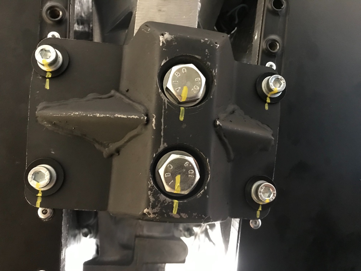
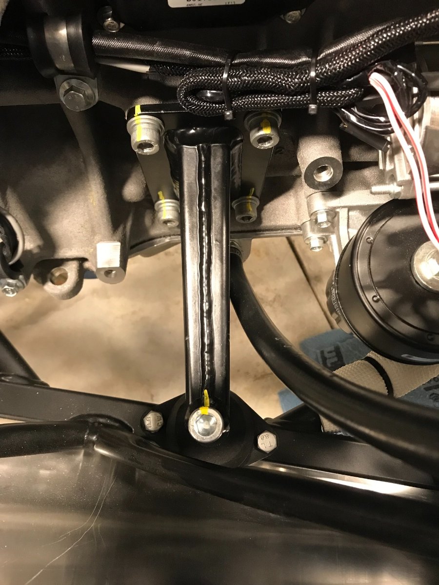
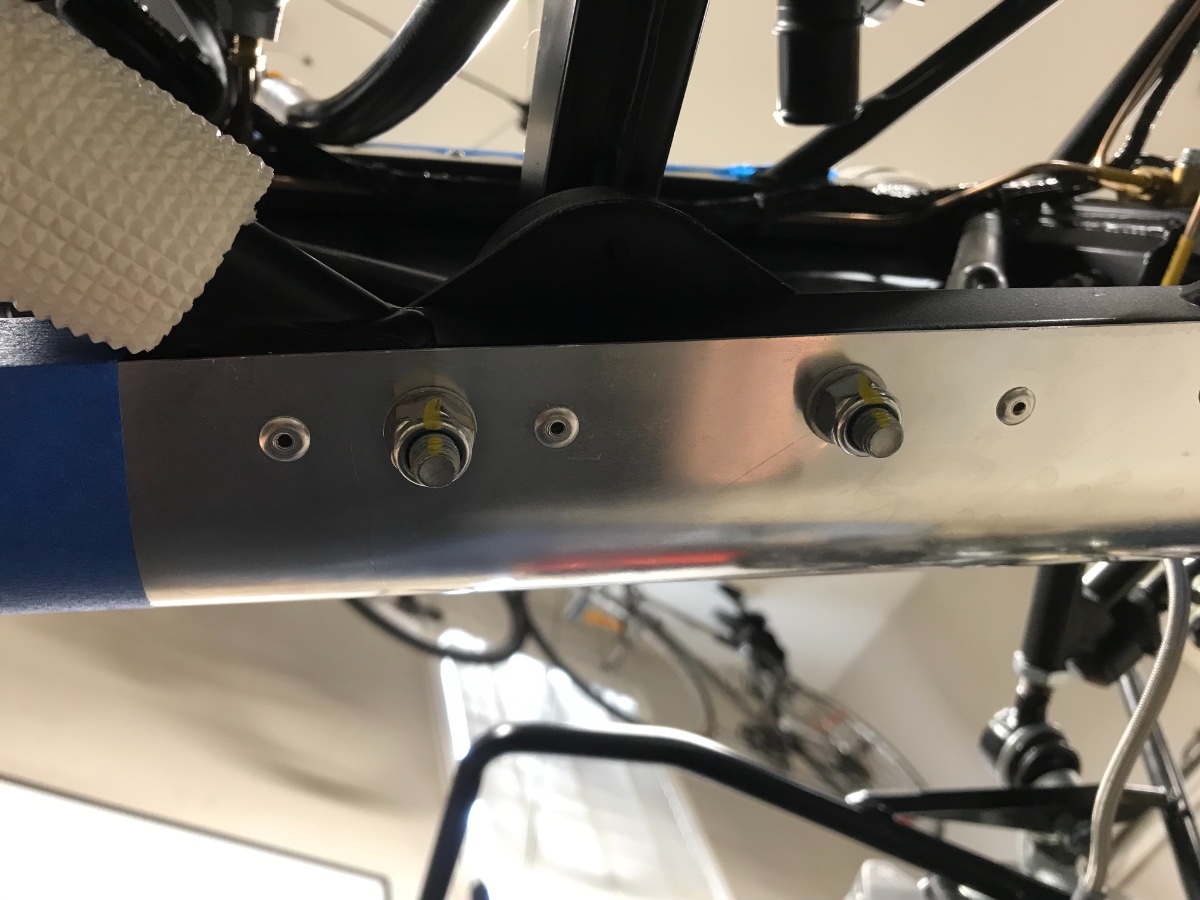
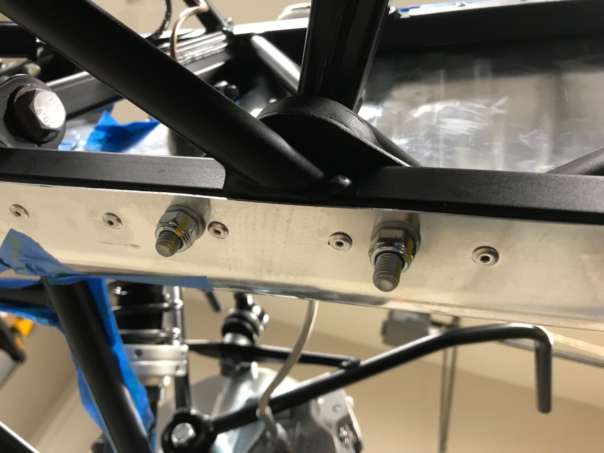
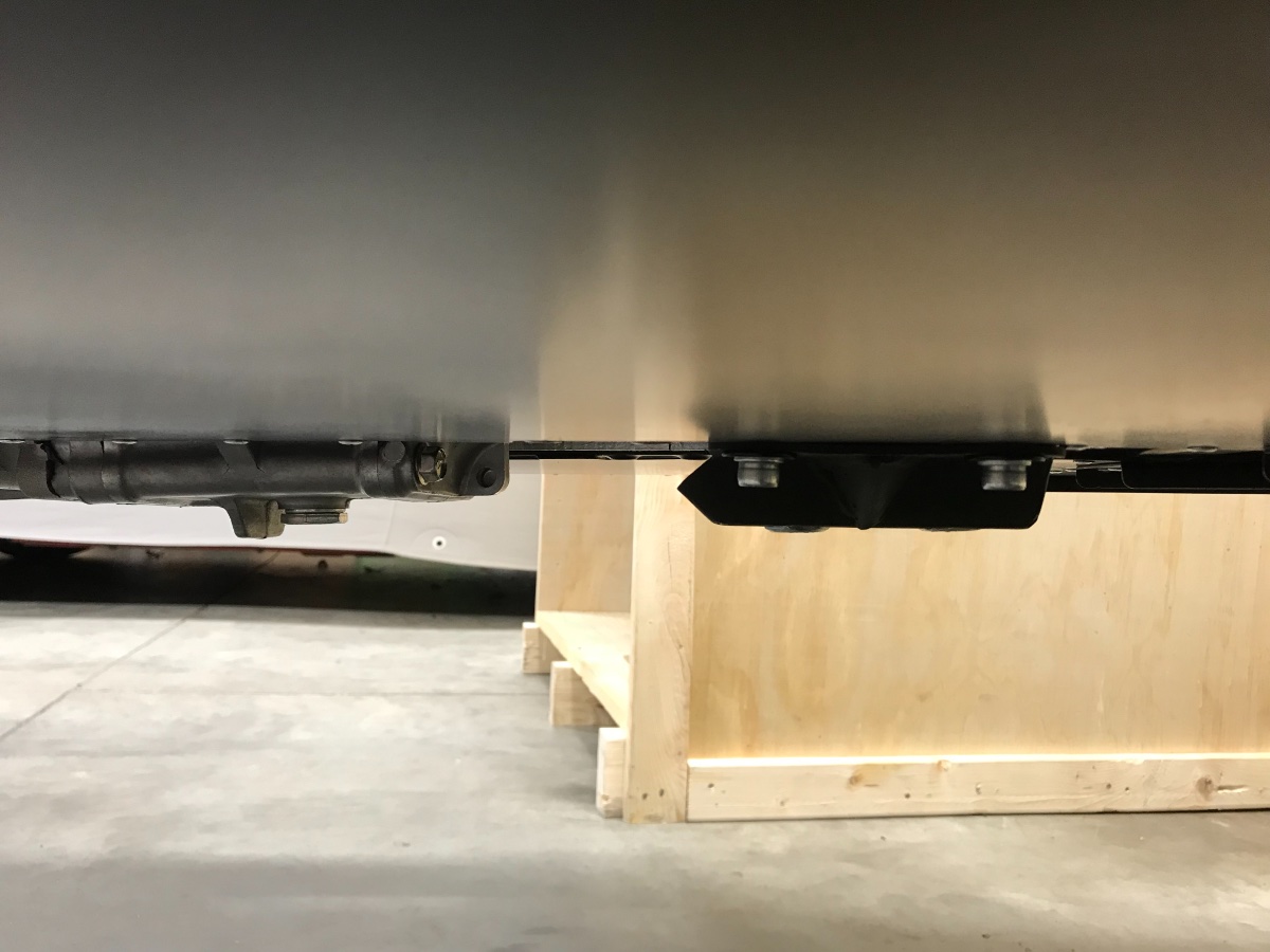
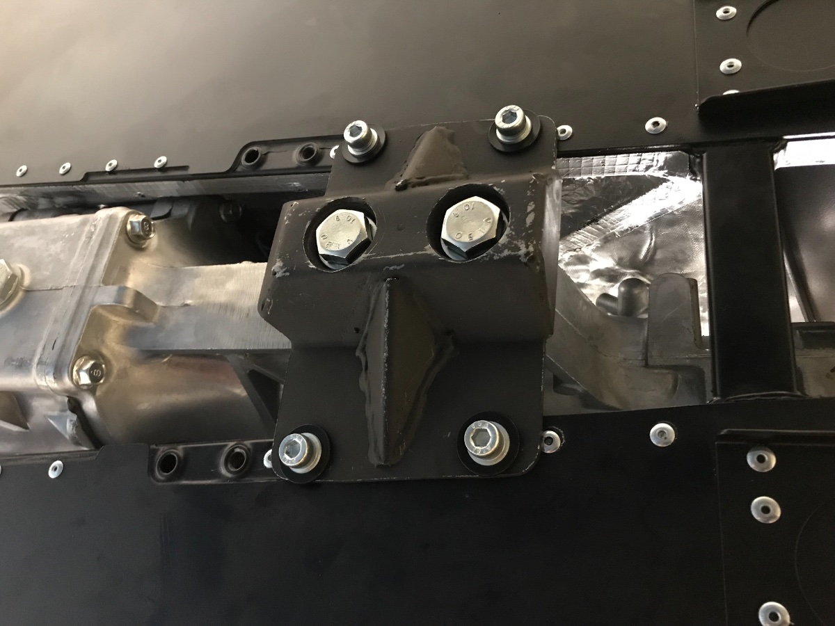
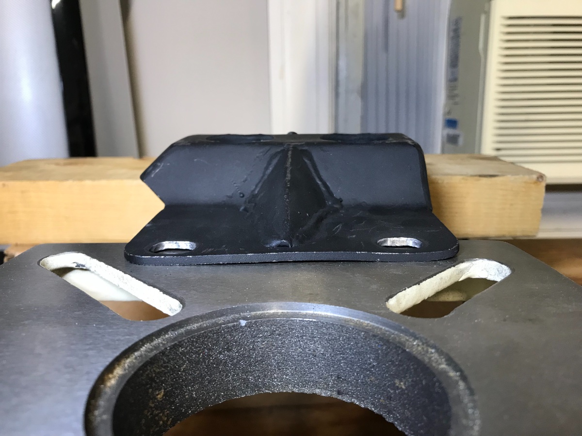
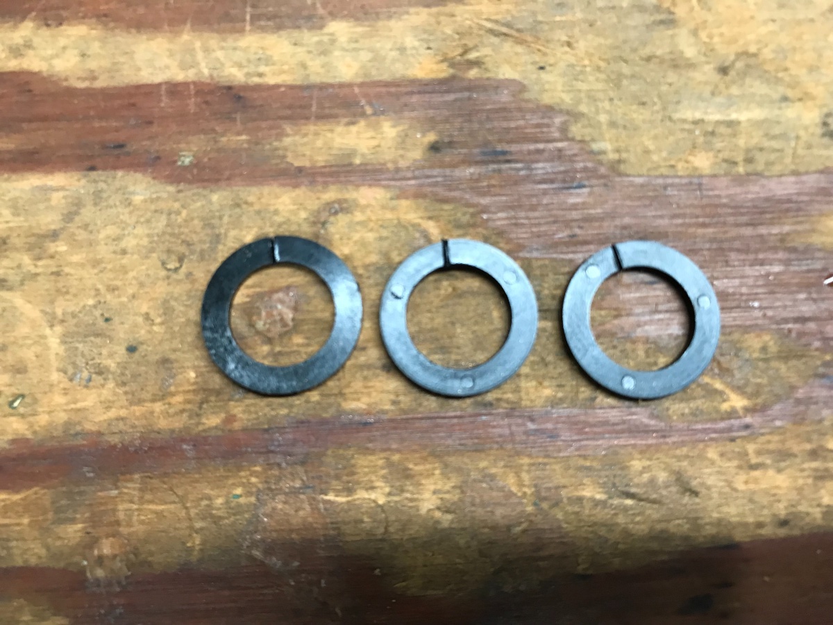
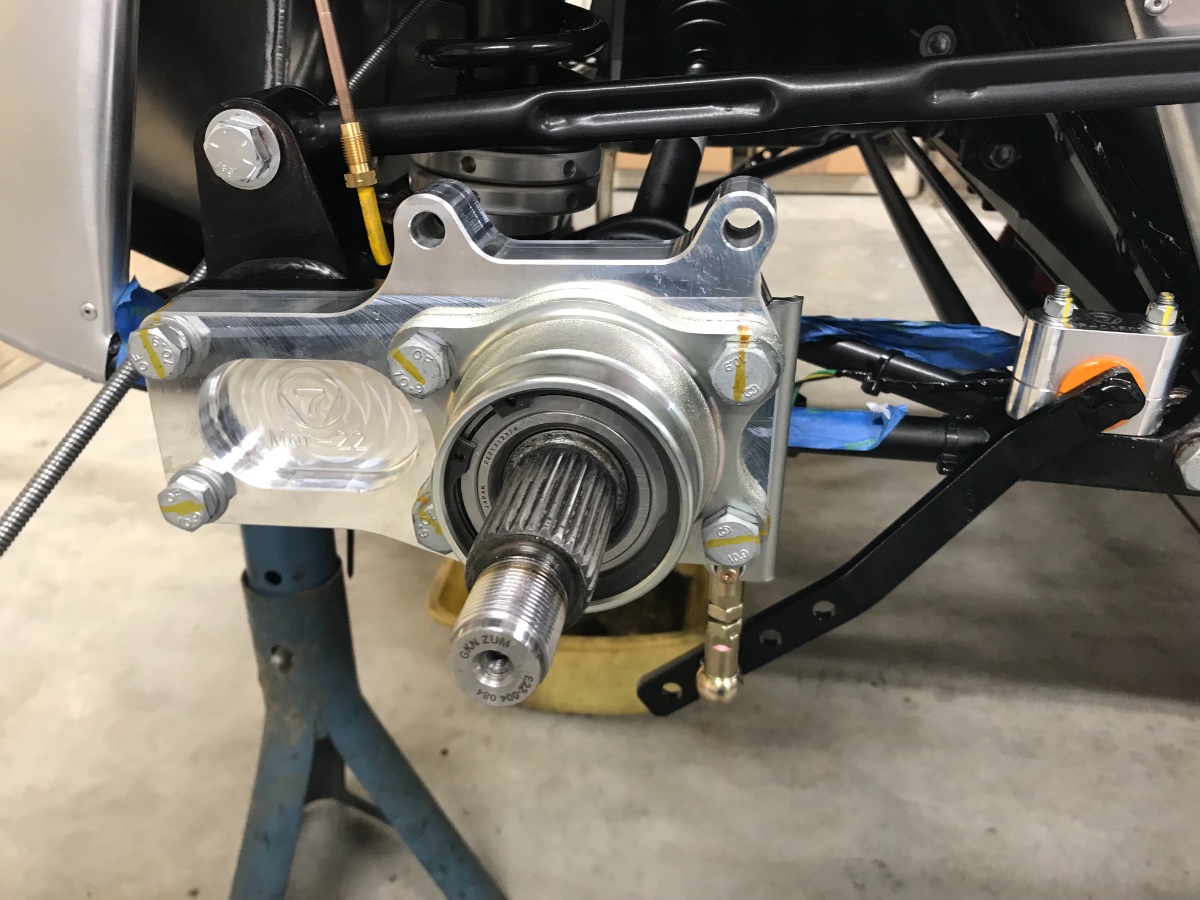
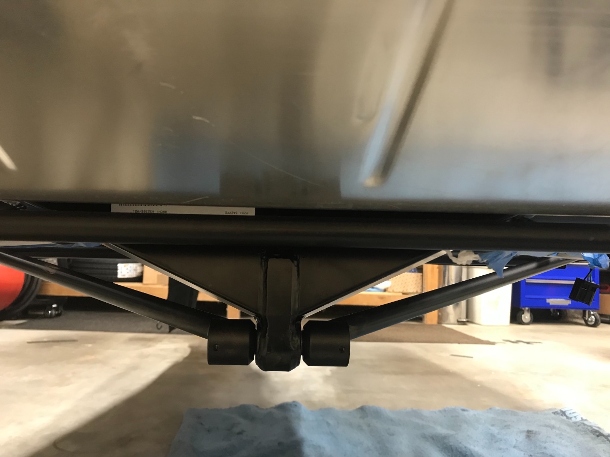
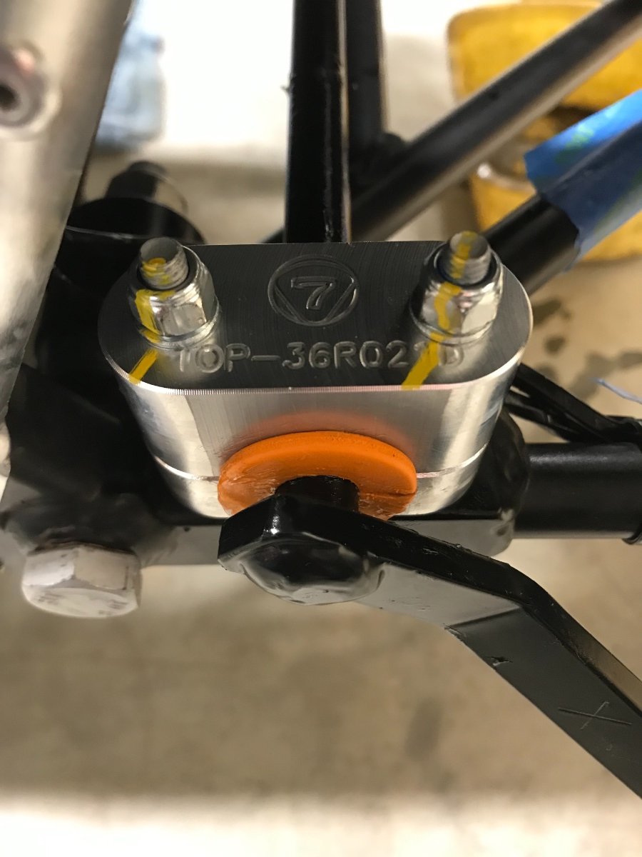
Buttoning Down the Mounts All the fuss centered on the gearbox mount. It required fixing the M14 thread in the gearbox aluminum housing and reworking the bracket to nudge the gearbox as far to the right as possible (2-3 mm) to reduce the level of contact with the heat shield on the LH side. The plan (and actual execution) was to get the gearbox aligned as best as possible, get its mount tightened and torqued first, and then tighten and torque the engine mounts. Thread fix: Received and used the NES22 tool to clean up the cross-threaded M14 hole in the gearbox housing -- worked perfectly!! (tool is made in Israel -- not in China!!) Gearbox "alignment": As mentioned before, once the engine+gearbox mounts were all bolted in loosely, I identified the need to shift the gearbox to the right to alleviate very tight fit on the left side. Leveraging carefully with a padded crawbar against the upper tunnel left rail I concluded that movement is limited by the mount bracket holes, so I decided to enlarge them further (I had already enlarged 3 of them because they wouldn't fit). I supported the gearbox with the floor jack and removed the bracket. Ground all 6 holes with a Dremel tool and touched up the holes with black chassis paint. Since I needed the gearbox nudged to the right, I enlarged the two M14 holes under the gearbox to the right so the bracket can be shifted left relative to the gearbox, and the four oval M8 holes to the left, so the bracket can be shifted right relative to the chassis, each set of holes by about 1-1.5mm for a total of about 2-3mm. Unfortunately I forgot to take a pic of the reworked bracket and am not in the mood to disassemble it for the 3rd time... Discarded the spring lock washers for the two M14 bolts as found one of them broken upon the above disassembly! That washer saw just a couple days of static duty under the very light specified torque (30 ft-lb)!! I decided to use Threadlocker Blue instead (as per an earlier Caterham spec) -- also to gain deeper bolt engagement after the clean-up of the cross thread. Another benefit of deleting the lock washers is getting the bolt heads to protrude a bit less under the car -- they are the lowest ground clearance point in the middle of the wheelbase besides the gearbox drain plug protective tab. I also reversed the four M8 bolts connecting the gearbox mount bracket to the chassis from the Josh R. to the Caterham orientation (insert from below) since it is much easier to apply counter-torque solo from below (open spanner instead of hex bit or Allen key). Started by torqueing the gearbox mount bolts - first the two M14 bolts, biasing the bracket as far to the left as it would go, and then the four M8 to the chassis with my dear friend Stevie leveraging the gearbox (padded crawbar against the top rail) as far to the right as it would go. Used the hardened oversize washers + regular washers under the bolt heads (2 per nut) over the enlarged holes in the bracket. Next torqued the engine mounts -- first brackets to engine block, then rubber blocks to chassis, then brackets to rubber blocks. Gearbox in final "aligned" position -- still very tight on the LH side: Gearbox mount torqued: (note two washers under M8 bolts - large black washers are 24mm OD, 2mm thick, hardened, procured from McMaster-Carr) Gearbox and mount in side view under car - notice protective tab on left in front of drain plug, and gearbox mount on right with the two M14 bolt heads barely protruding without lock washers. LH engine mount torqued: RH engine mount torqued: Key lesson: I decided on and fully recommend the following sequence for tightening and torquing the powertrain mounts (starting with all bolts in place finger tight): 1. Gearbox mount bracket to gearbox housing 2. Gearbox mount bracket to chassis 3. Engine mount brackets to engine block 4. Engine mount rubber blocks to chassis 5. Engine mount brackets to rubber blocks Next posts: Engine accessories, wiring, gearbox top up Cheers!
-
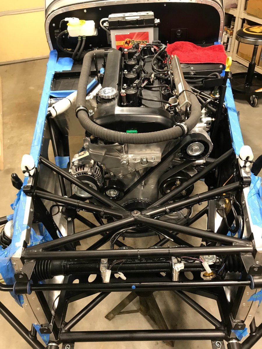
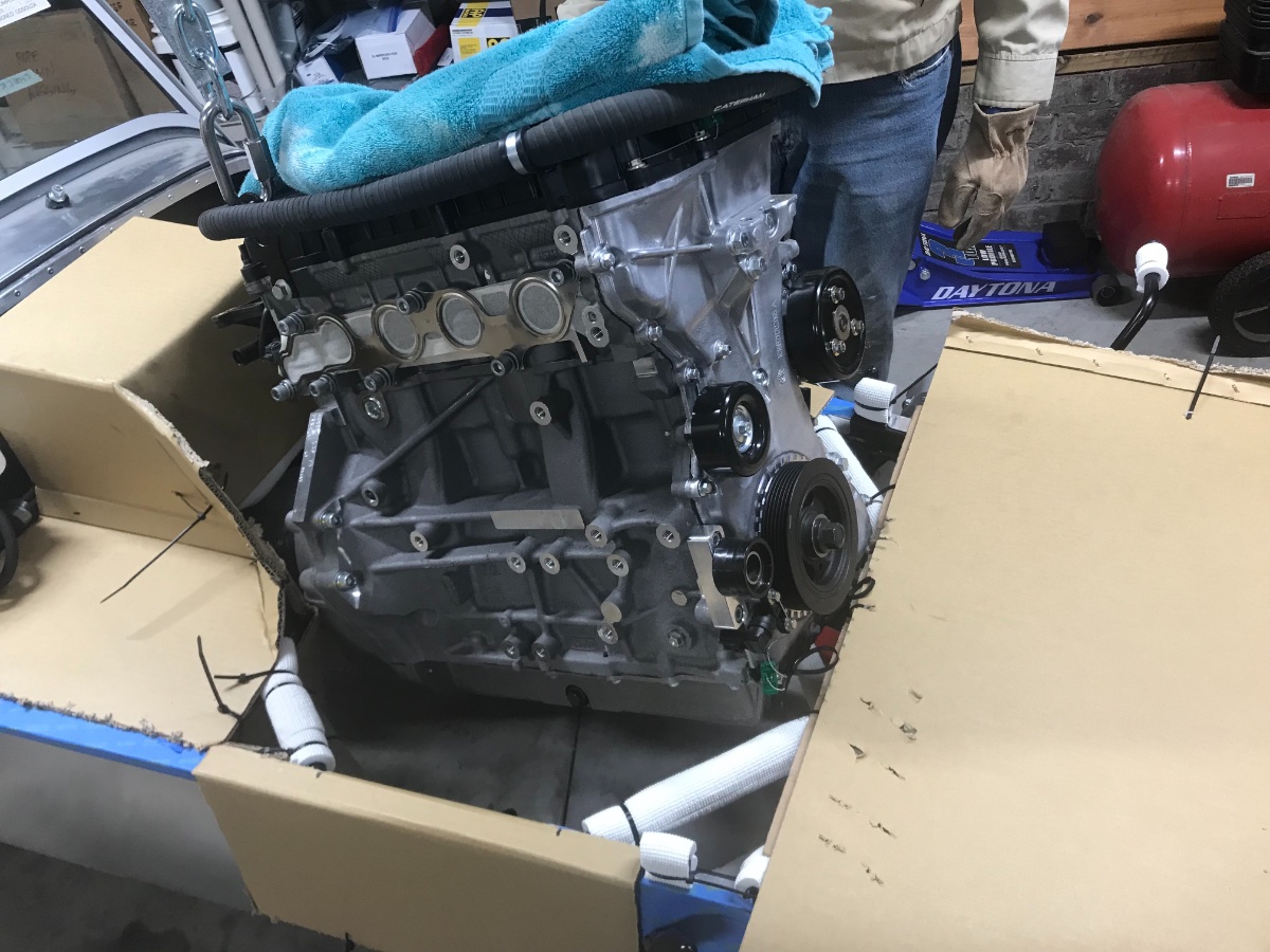
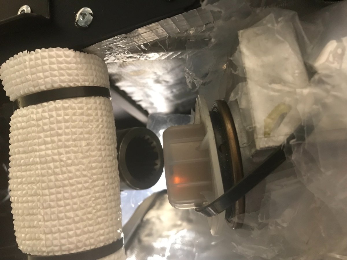
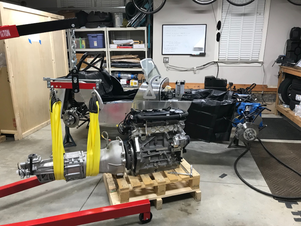
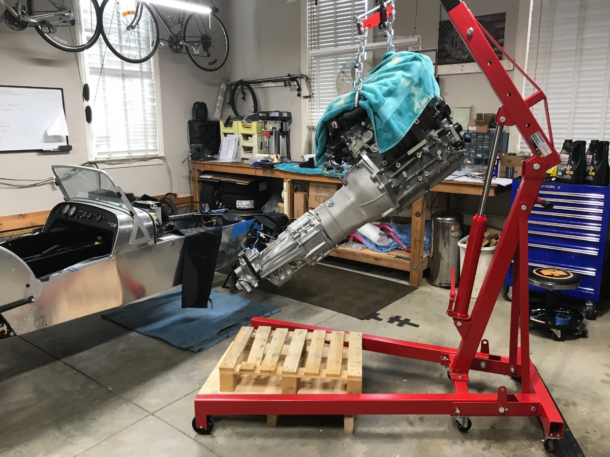
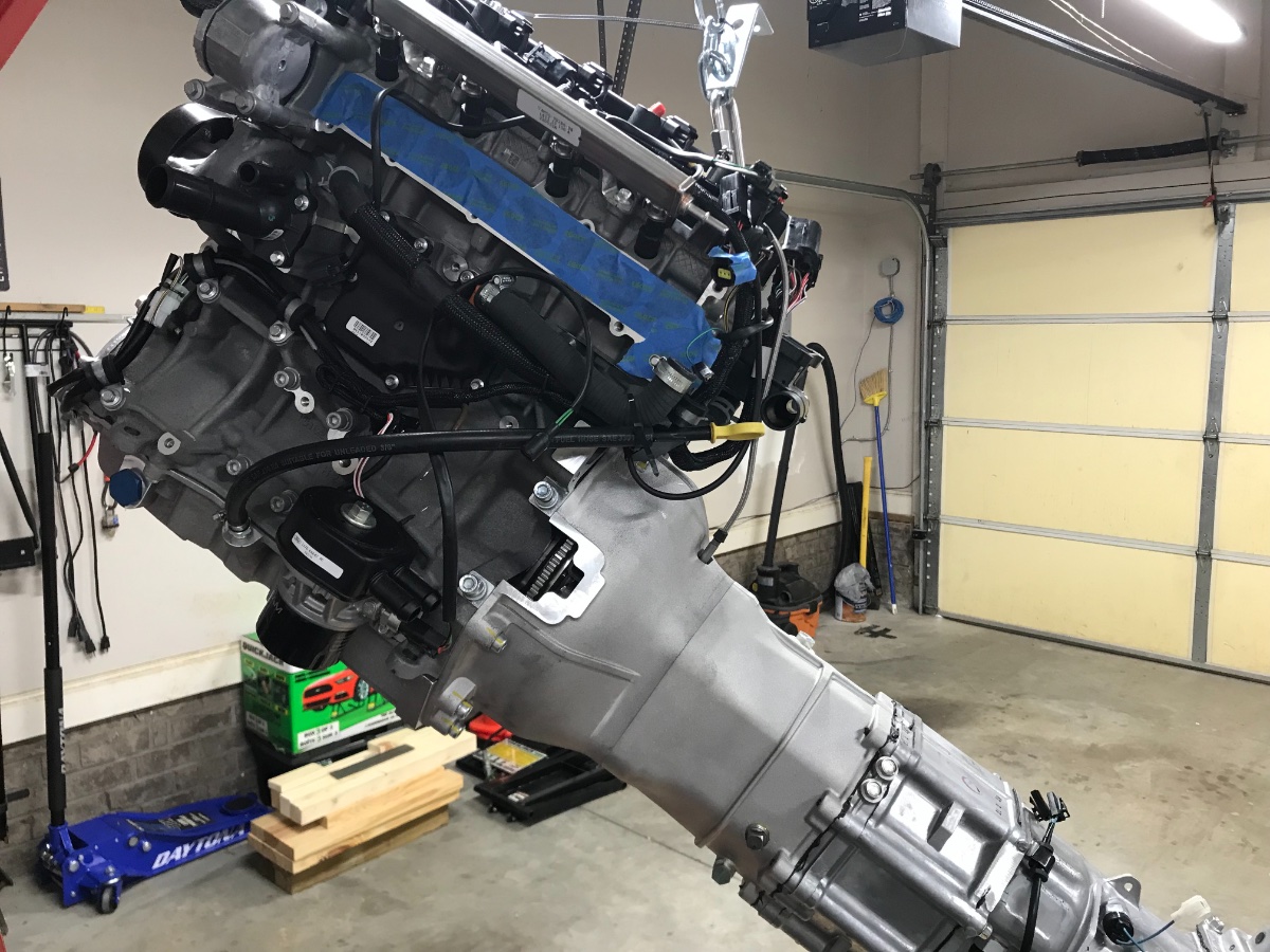
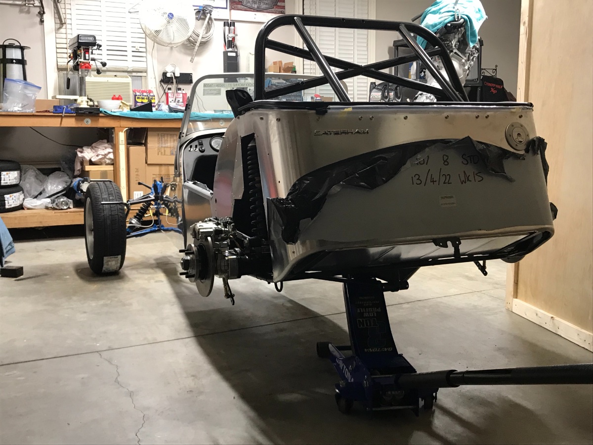
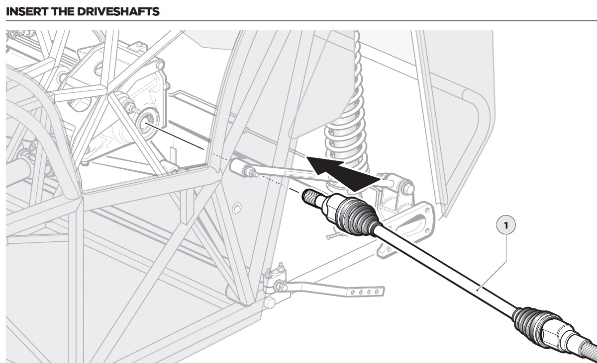
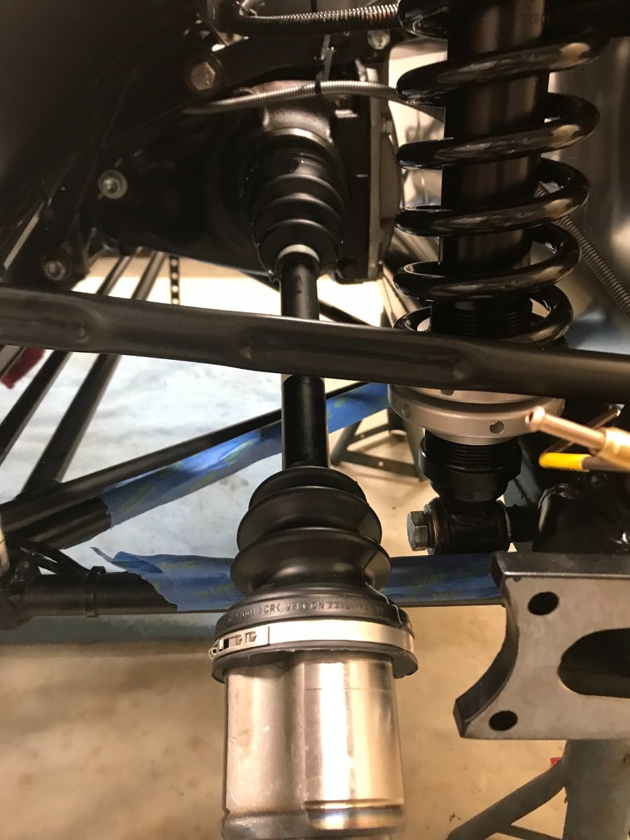
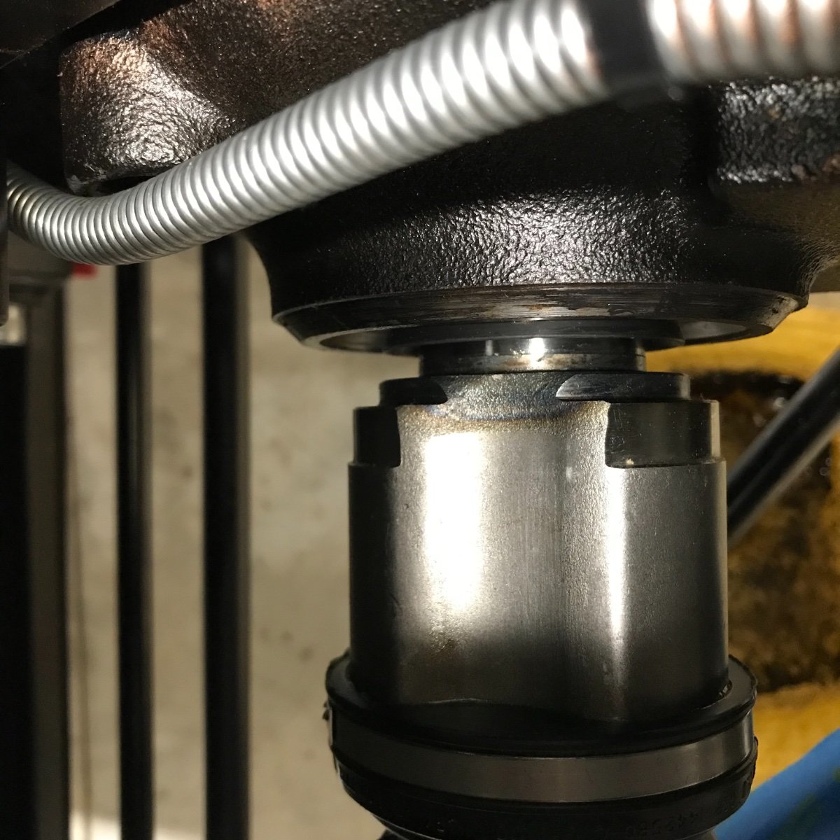
Engine+Gearbox Install This is quite a big deal in the overall scheme of building a Se7en. This task took place more than a week ago but I didn't have enough quiet time to post. So here it is, finally. This is the first task since the unload and moving the CBU off the crate and onto stands that I engaged help, this time from my good friend and neighbor Mike C. The first two pics show the critical point when the gearbox is held as high as possible in the tunnel while the lower front of the engine is about to clear the frame, just before the "flare". The crankshaft pulley passed through with no interference once the protective cardboard was moved. Notice no accessories left on the engine. The next pic shows one of the most critical potential collision points between the (unprotected) black manifold above the oil filter and the (protected) master cylinder (also seen above). This gets resolved (nothing broke here!) once the engine is dropped gently into position. All in all the powertrain went in without too much trouble. Took us about 2.5 hrs to get it in near final position with the propshaft splines engaged and the three mounts installed finger-tight. We installed the LH engine mount bracket only when the engine was near final position (the RH one had been installed on the rubber block and swung out of the way ahead of time). Had to start removing some of the protective cardboard and the gearbox wrap during the "insertion" to get the powertrain all the way into position. Used floor jack with a large rubber block to support the gearbox in the final stage of the "insertion" to engage the propshaft and install the gearbox mount. The latter proved a bit more more challenging than expected -- read on. The first "engagement" step and biggest challenge was to maneuver the gearbox end to meet the propshaft end, remove the gearbox output cap, insert the propshaft, know whether the splines engaged, and get it all the way in quickly to not lose too much oil. To keep the gearbox from rotating while twisting the propshaft to engage the splines I installed temporarily the gearshift lever and put the gearbox in gear. In retrospect not sure this was necessary... Either way we still lost lots of gear oil. The next two pics show the point just before the propshaft and gearbox contact -- gearbox protective wrap is still on, as is the gearbox shaft cap, both about to be removed. Gearbox is supported by the floor jack. The white protective sleeve over the cross bar is also still on and not in the way. View from above: View from below: The following pics show the status right after the "insertion": Propshaft engaged: At this stage we got both engine mounts bolted finger tight and then slackened off and disconnected the engine hoist, with the gearbox still supported by the floor jack. The gearbox mount is the last one to bolt in but the first one to torque down as will be described later. Engine in near final position (loose mounts): LH Engine Mount: RH Engine Mount: Gearbox mount: (a later pic for reference only, after M14 thread fixed; actual status at this stage was only one M14 bolt screwed into the gearbox housing) No mount fasteners were tightened or torqued yet at this stage. Issues (status right after initial install): 1. Cross-threaded rear mount M14 thread in gearbox housing, seems like only 2 initial coils -- ordered an NES22 thread repair tool. If it wouldn't work would order a Helicoil kit. 2. Spilled gearbox oil -- ordered 2 liters Liqui-Moly 75W-90 GL-4. 3. Gearbox very tight against heat shield on LH side. EDIT: LESSON LEARNED / IN HINDSIGHT... In hindsight, I think I would have chosen to change the sequence and install the engine+gearbox in the car after the front suspension and before the propshaft and rear axle. Josh's recommended sequence, with front suspension followed by propshaft, diff and rear axle is based on the idea that once both front and rear wheel ends are installed you can mount all 4 wheels and roll the car around as needed to facilitate engine+gearbox installation. I found it easy to maneuver the car in the garage on the front wheels and a floor jack with a rubber cushion supporting and "steering" the rear (under the diff in my case, but could have been under a rear frame junction), without the rear wheels mounted. On the other hand, I am convinced that having the engine+gearbox in place and simply inserting quickly the propshaft into the gearbox instead of maneuvering the engine+gearbox to mate with the propshaft would have been much easier and would have minimized the loss of gearbox oil.
-
Chassis / Body Prep for Engine+Gearbox Install Before starting wrapping and padding I installed the horns. Used rubber coated foam sleeves to wrap vulnerable frame tubes, protrusions on top of the body edges and the first bottom cross member in the tunnel. Also covered with foam sleeves the wiring looms and connectors in front of the battery and the master brake cylinder area. 22 mm ID/32 mm OD foam sleeves work well for frame tubes. Then used thick cardboard (from the gearbox packaging) to cover the front top part of the frame, side walls and edges of the engine bay, battery, and the tops, fronts and edges of the footwells. Zip-ties are magic for everything.... We are now ready for the install (next post!).
-
You got me thinking... Probably first priority would be for the lines in the tunnel and where they are not directly visible or are exposed to high heat. Lines running along the round tubing in the front probably not critical?
-
Great idea, Bill! Just for the fuel line or for everything? There is a $hitload of zip-ties on this thing....
-
Engine+Gearbox Mounts - Preparation and Trials Before actually trying to install the engine+gearbox in the chassis you need to make sure that the mounts fit the attachment holes on the chassis, you have all the fasteners and tools to tighten them, and you know what needs to go where when. You do not tighten any of the joints until the engine+gearbox are in their final correct position. This part took considerably more time and work than anticipated due to, uh... shall we say, design and manufacturing imperfections.... Engine mounts: The engine mount brackets are attached to the respective rubber blocks with single 1/2" hex socket head bolts which thread into sleeves in the rubber blocks. You want to confirm at this stage that the threads are good. I discovered that the hex socket head of these bolts is 3/8" (H10 won't fit). Ordered a hex bit from Amazon. Next step is install (loosely) the rubber blocks on the chassis rails with 2 bolts each that go through the rails, washers and nyloc nuts below. Encountered 2 issues: a) needed to clean out the chassis holes from below (21/64" drill bit) b) needed to grind the edge of the RH rubber block flange to fix interference with a chassis weld. Touched up the ground area with black chassis paint pen. before: and after: I then installed loosely the RH engine mount bracket onto its rubber block (seen party in the pic). Left the LH bracket out as the LH side of the engine block presents several obstacles. Gearbox mount: The gearbox mount bolts to the gearbox (two M14 bolts) and to the chassis (four M8 bolts) from below. First I verified both M14 threads in the gearbox housing accepted both bolts. I then cut out small pieces of the heat shields at the bolt locations and inserted the 4 bolts from above (per advice from Josh R) over the small washers, making sure they are seated directly on the rail, not on the heat shield. Note 2 rivets on each side between the bolts - I considered adding spacers (washers) between the gearbox mount and chassis to clear the rivets but ended up not doing so as explained below. Next I tested the gearbox mount fit and discovered that the holes are about 1.5mm too far apart laterally. Enlarged the front holes and one of the rears on the inside with a Dremel tool (unfortunately I don't have a milling machine) and confirmed fit. Planned to use the large OD washers over the enlarged holes. Once I could seat the mount over the bolts I performed trial torquing (20 Nm) with standard (non-nyloc) nuts. Upon disassembly I found that the mount flanges are riding on the 2 rivets on each side and bending to make contact with the raised rail holes. Conclusion: not to use spacers between the rails and flanges due to the flange bending. Note center of flange bent up/ends bent down due to rivets. The washers under the nuts got also bent due to the oval and enlarged holes in the flanges -- not acceptable. Ordered hardened and thicker M8 large washers (24 mm OD, 2 mm thick) from McMaster-Carr. Ended up using them together with (under) the available small washers (2 washers under each nut) to prevent washer bending. Intending to show pics of the complete installation in the powertrain install post. Next Post: Chassis / Body Prep for Powertrain Install Cheers!
-
Thanks! The fuel line comes from Caterham routed and protected inside a corrugated plastic sleeve and zip tied along the way. All that's left is to plug it to the fuel rail.
-
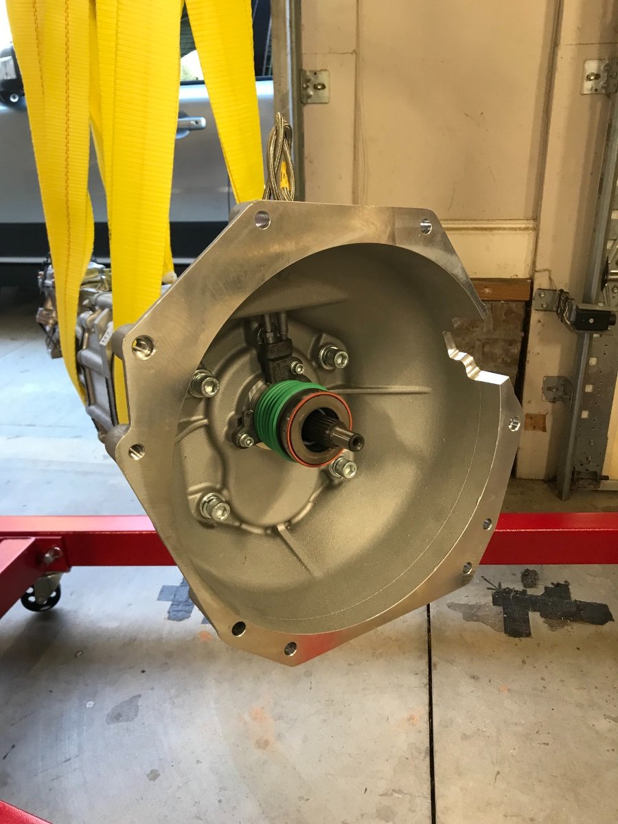
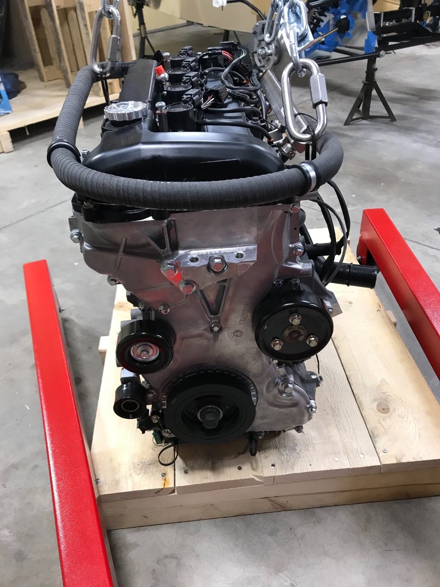
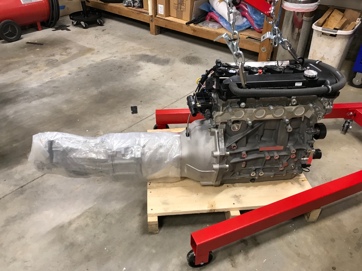
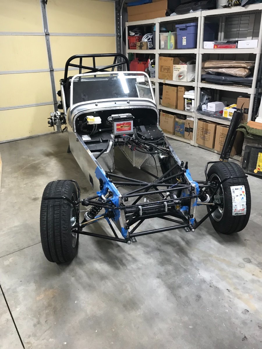
Hello All, It's been a while and there has been some good progress since the last post but need to catch up with the documentation. This and the next couple posts will cover prep and installation of the powertrain in the car. Gearbox Attachment to Engine This is quite straightforward. I left the engine on the pallet it came on after unscrewing and removing the top and walls of the crate, and used the engine hoist and leveler to lift and hold the gearbox. Next you need to remove the starter and the bell housing from the engine. The bell housing then gets attached to the gearbox and the assembly gets attached to the engine. Placed the removed bell housing-to-engine bolts in cardboard template to reuse in same positions. Installed bell-housing to gearbox using the 4 socket head cap bolts and washers pre-installed in the bell-housing and torqued with no grease or Threadlocker to 68 Nm (50 lb-ft). In preparation for attaching the gearbox+bell housing to the engine I applied thin layer of anti-corrosion gel (Superlube 82003) to the spline and the bell-housing face and moly grease to the clutch fingers interface with the thrust bearing. With the gearbox hanging with straps from the engine hoist and the engine sitting on the pallet, it took a few adjustments with the hoist and leveler and rocking the gearbox about its axis by hand to engage the splines. Started with the 2 bolts with guide sleeves at 2 and 8 O'Clock. Once splines were engaged there was little to no resistance to tightening these two bolts alternately part of the way, followed by the rest of the bolts. Torqued in star pattern with no grease or Threadlocker to 47 Nm (35 lb-ft). Some folks say use anti-seize lubricant on the threads but my concern is that unless this is expressly specified it may result in excessive stretch load on the bolts at the specified torque - the bolt stretch load is approx. inversely proportional to the friction coefficient in the thread at a given torque. Prep for Installation -- Engine+Gearbox Besides the starter and bell housing, you also remove the coil cover, plenum, alternator, serpentine belt and tensioner (the coil cover to protect from chain damage, the plenum to protect it and provide better access). Make sure to seal off the ports in the head and in the plenum; I used masking tape. I also moved the wiring looms routed in front of the sump to the side of the engine to minimize risk of catching on the frame during lowering. All the stuff removed from the engine... Next I reconfigured the engine hoist+leveler for the engine+gearbox lift. Before hooking up the leveler chains to the engine I covered the top of the engine for protection. I then proceeded to perform some trials to assess the the range of height and angles and the sensitivity of the hydraulic lowering valve under load. Had to adjust the chain lengths several times to ensure sufficient "dive angle" and minimize sideways tilt. In anticipation of losing some oil during the insertion of the propshaft end into the gearbox I loosened slightly the gearbox fill plug (14mm open wrench) and placed a warning sticker on inside of windshield re gearbox oil (Josh R. tip). Finally, I wrapped the gearbox with thick plastic sheeting (cut from the original gearbox packaging bag) to protect the heat shields in the tunnel during the "insertion" (great tip from Chris Collins's blog). The next step was the "choreography" of the engine hoist path -- making sure there is sufficient maneuvering room in front of the car for the "approach" and no overhead obstacles in the envisioned path (light fixtures, ceiling fan, garage door rails, etc). Based on that I decided that I needed to move the car to maximize room in front. I installed the front wheels (they look cool!!), lowered to the ground, lifted the rear with floor jack under the diff and maneuvered the car with the jack to its new position. Initially I thought of leaving the front wheels on for human protection when moving around the front, but I quickly realized that there will not be enough clearance under the wheels for the engine hoist "outriggers" so I removed them. Next posts will cover chassis/body prep and the install. Cheers!
-
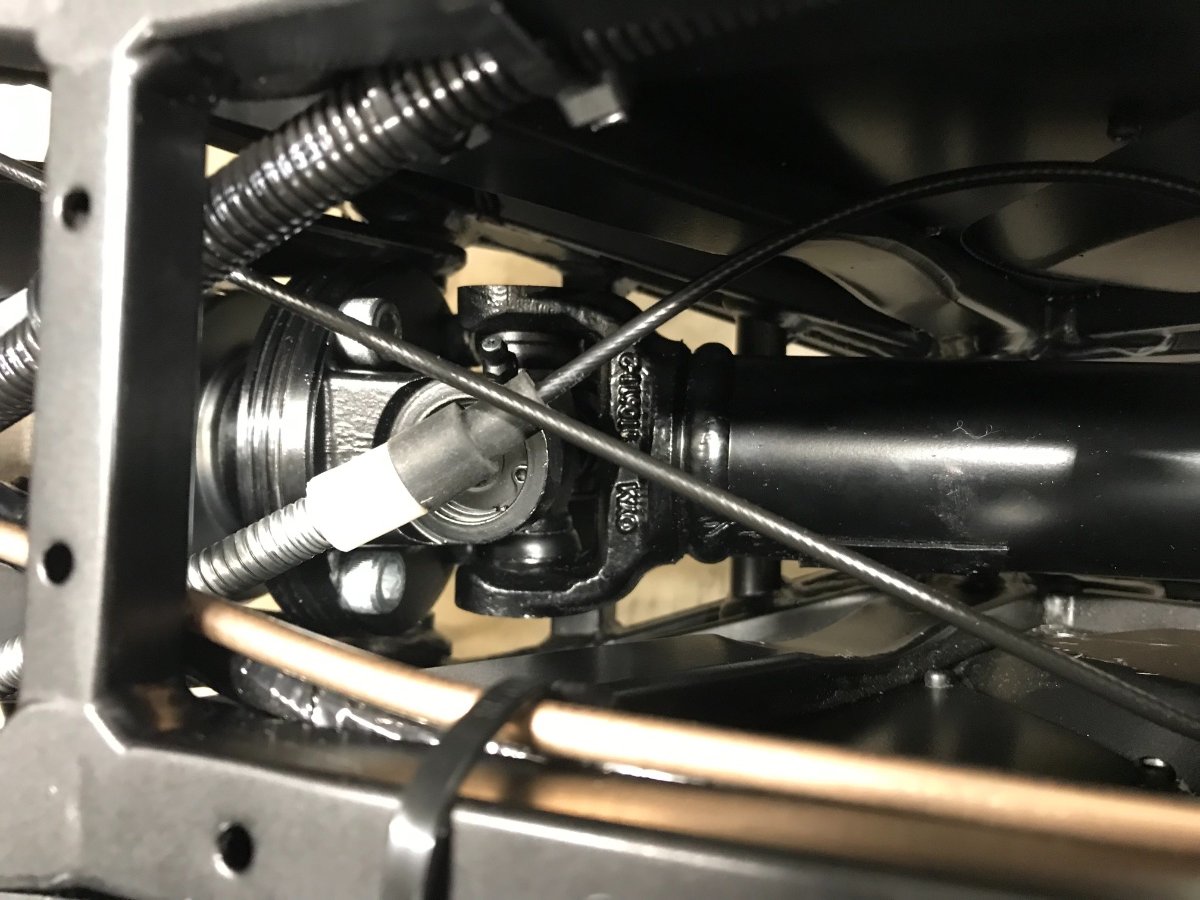
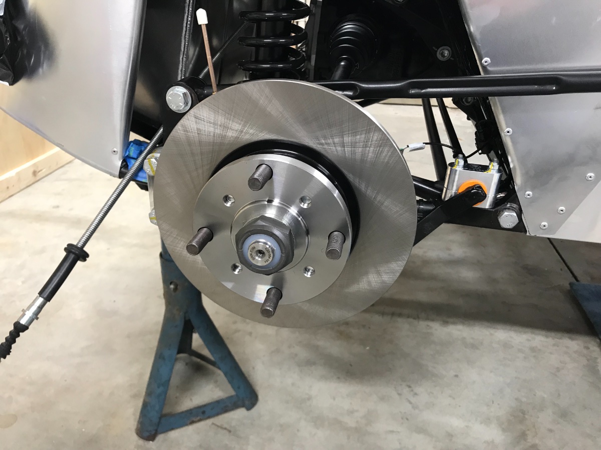
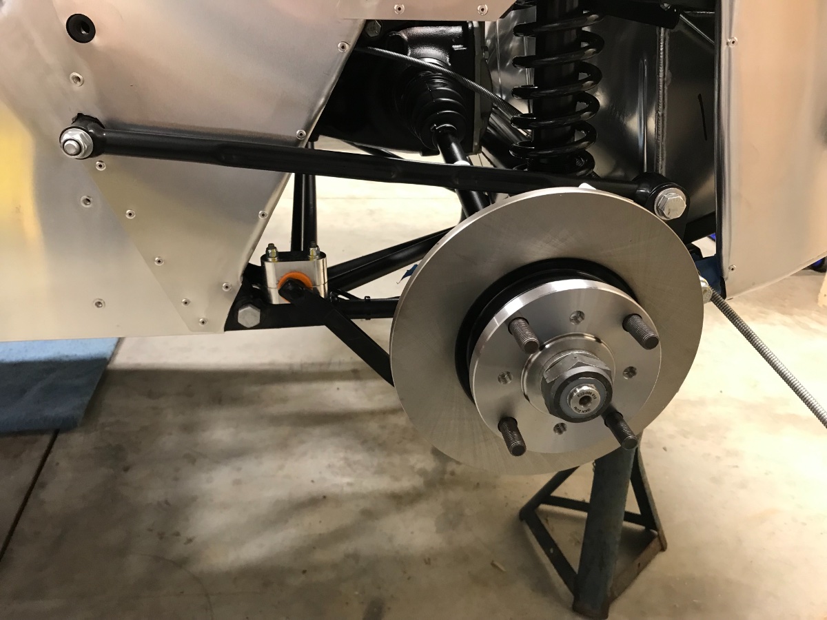
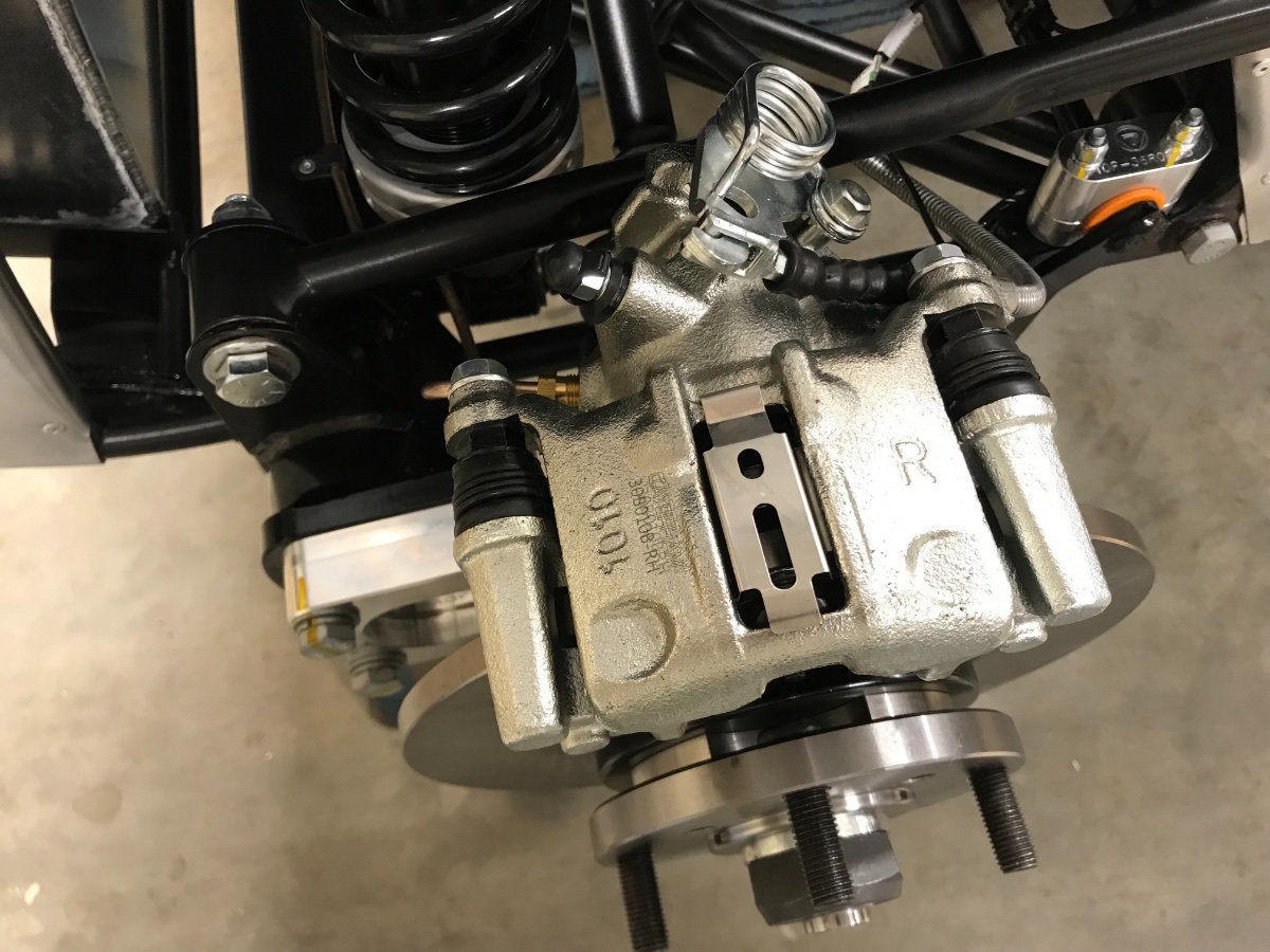
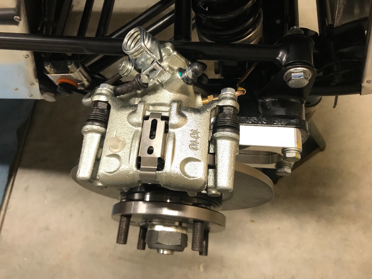
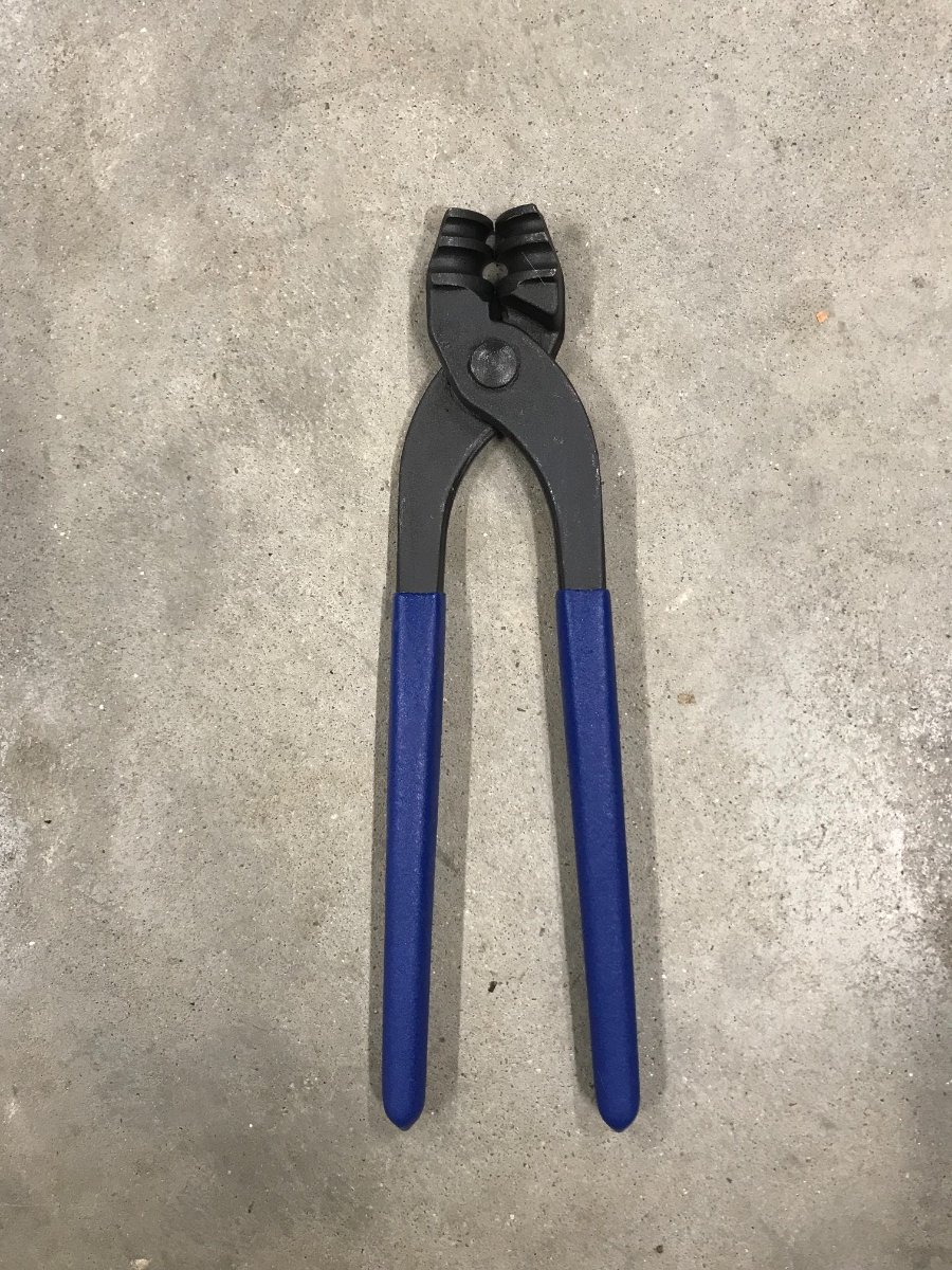
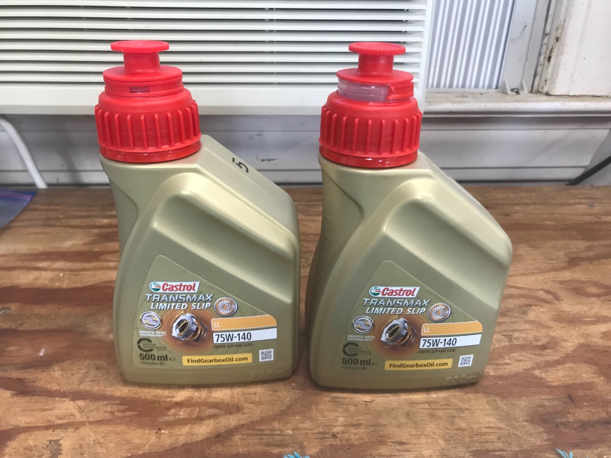
Update: Diff Fill Completed the diff fill. Accounting for a bit of the necessary overflow, it took ~1.2 liters (LSD) - more than reported. No torque spec for filler plug - torqued by feel. 3rd 0.5L bottle after completion of fill Propshaft attachment to Diff Attached propshaft to diff flange with the 4 bolts. Access and torquing are a bit difficult. Ended up supporting the propshaft from below by floor jack, inserting the bolts from above and tightening from below. Access to torquing one of the bolts is compromised by a grease nipple - requires a spherical hex bit. Unable to torque the bolts to spec at this stage due to difficult access and no good way to provide counter-torque; will need to loosen one bolt at a time, apply Threadlocker Blue and torque once handbrake is operational. Lifting and supporting the front of the propshaft in the tunnel from below and orienting each torqued bolt off center, not dead bottom, allows the best access from below with a long spherical hex bit+extension. May need to increase the target torque to account for the small angular misalignment... (x 1/cos). View from above. Note grease nipple in "upper" side of UJ yoke right in front of bolt. What you need in order to torque the propshaft bolts: Long 8mm hex bit with spherical end. Hub+Disc Units and Driveshaft Nuts Received the LH driveshaft nut from RMC; both LH & RH nuts are 42 mm hex. Lubed the driveshaft outer splines with anti-corrosion gel and mounted the hub+disc units. Hub & disc come preassembled and torqued and are non-handed. They glide onto the splines with no issues. Installed the driveshaft washers and nuts and tightened to the extent possible without functioning brakes. Rear Brakes Caliper Assemblies: Installed the brake anchors, pads and calipers. This is a pretty regular floating caliper design with direct actuation of the parking brake on the piston. The 2-piece caliper pin design is quite interesting but assembly is straightforward enough. The pins come lightly greased but I lubed them (as well as the pad contact surfaces with the piston, caliper and anchor) with standard brake grease. No pad free play detected after installation. Tip: Do an assembly dry-run before applying the various lubricants and thread lockers. Parking Brake Cables: Routed and attached parking brake cable ends to calipers. This required loosening the cable adjuster to provide as much slack as available with the lever pulled up to max. vertical, and a little fight to hook the cable on each side. Made sure the speed sensor cable passes above the parking brake cable. Tip: Hold off zip-tying the parking brake cables until after parking brake adjustment is complete. Brake lines: Attached the rear brake lines to the calipers. Very straightforward -- no fittings or washers required. Bent RH line to align using tube bending tool - no issues. Parking brake adjustment will need to wait until brake system is filled and bled. Access to the adjuster is easy from the trunk with the plywood floor removed. Tube bending tool Next Chapter: Engine + Transmission... Cheers!
-
Than you! The SuperLube 82003 does not come with the kit. It is not really a sealer; it is an anti-corrosion gel/grease that I decided to use because the axle tube and bearings are steel and the ears are aluminum. I decided not to use sealer in case I want to play with camber/toe alignment shims between the tube flanges and ears. I used the same grease between the bearings and driveshafts. Took some of the cues from Chris Collins' blog, which I think is the best source for guidance other than "my dealer" Josh Robbins. Good luck and cheers!
-
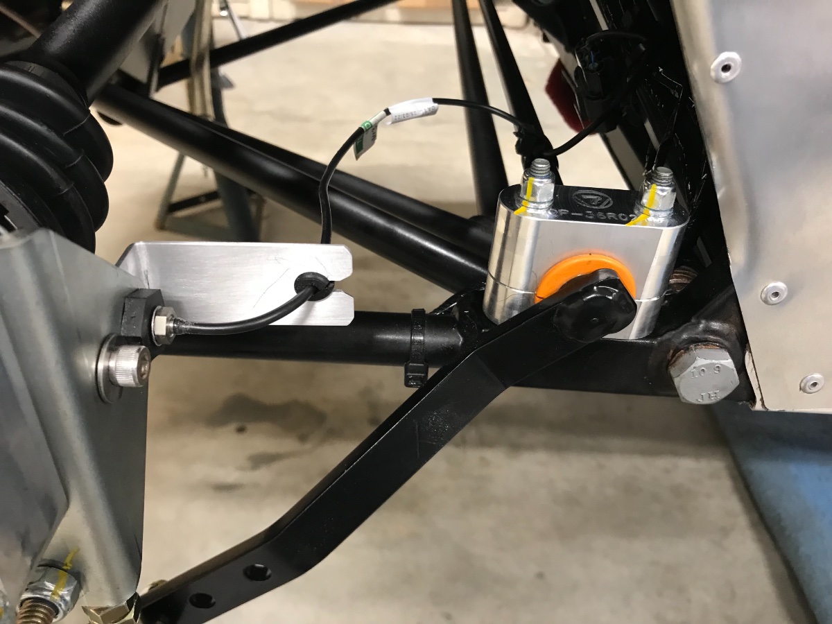
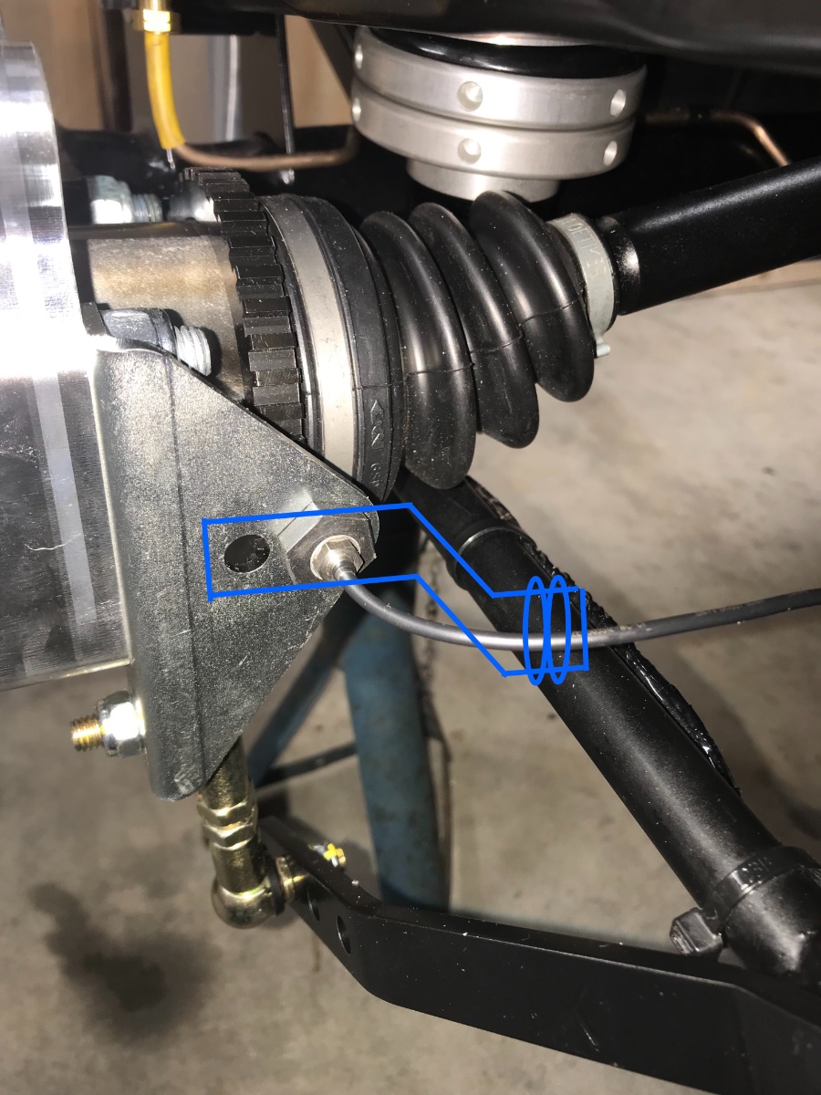
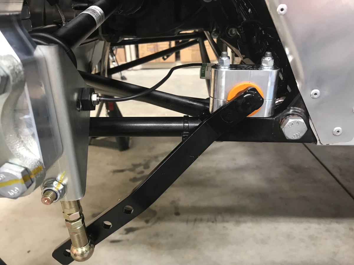
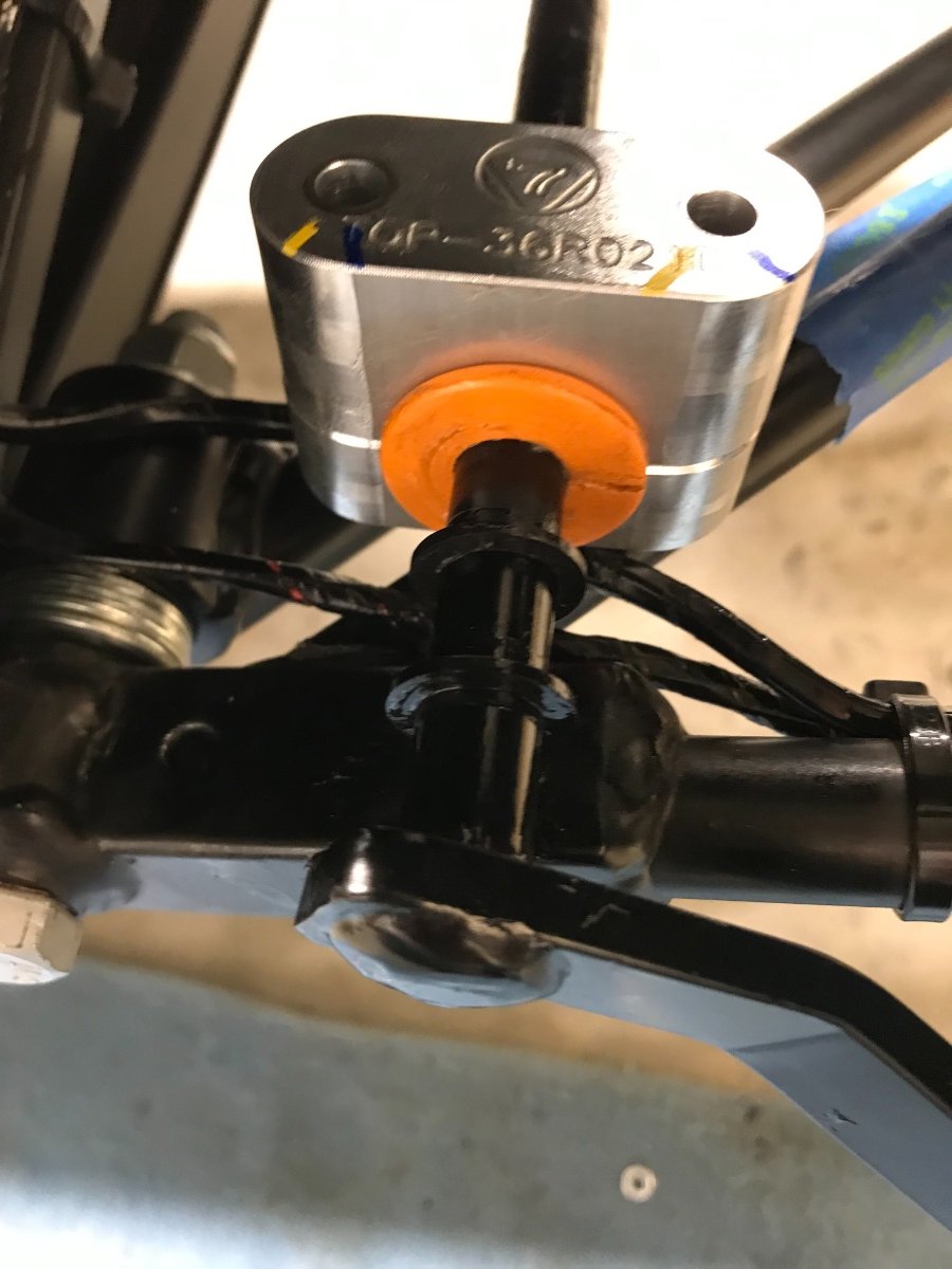
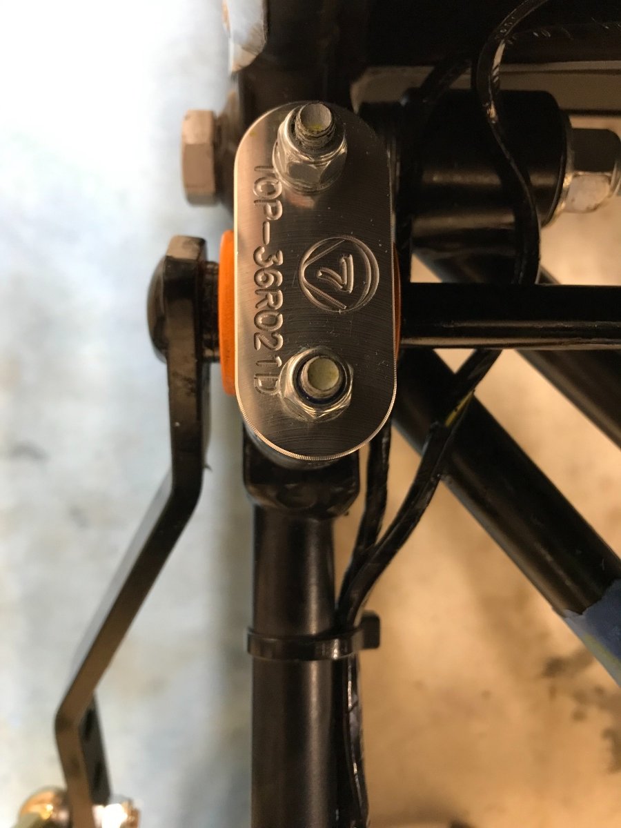
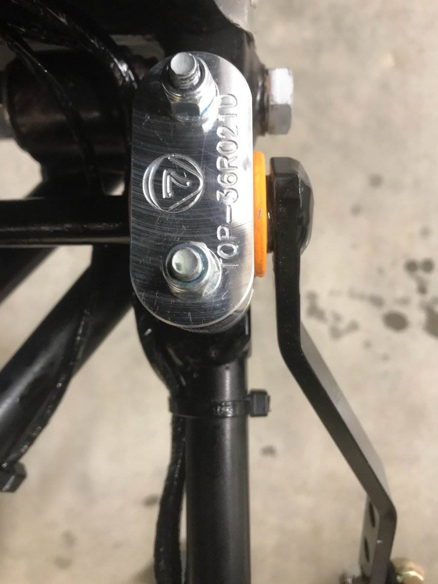
Speed Sensor wire strain relief in follow up to the recent discussion on the topic, I made a little aluminum bracket similar to the concept in my last post. Instead of a zip tie I am using a small grommet. I also moved the clamping to the ARB further inboard so the swept angle and length change between jounce and rebound are smaller.
-
100% agree. The issue is the termination at the sensor. Was thinking along similar lines -- a small aluminum bracket bolted to the extra hole just outboard of the sensor and under the sensor itself, kind of like below, and zip tie to it. There is not enough length to route the way you show (keep in mind the suspension in the pic is in full droop).
-
I don't think that's the case. The ARB is a natural pivot point and the motion there is miniscule. At the end of the day you need to have a pivot point somewhere to accommodate the relative motion. If you put it on the radius link it will still have a pivot point somewhere on the chassis. However the issue is at the sensor end (see my next reply).
-
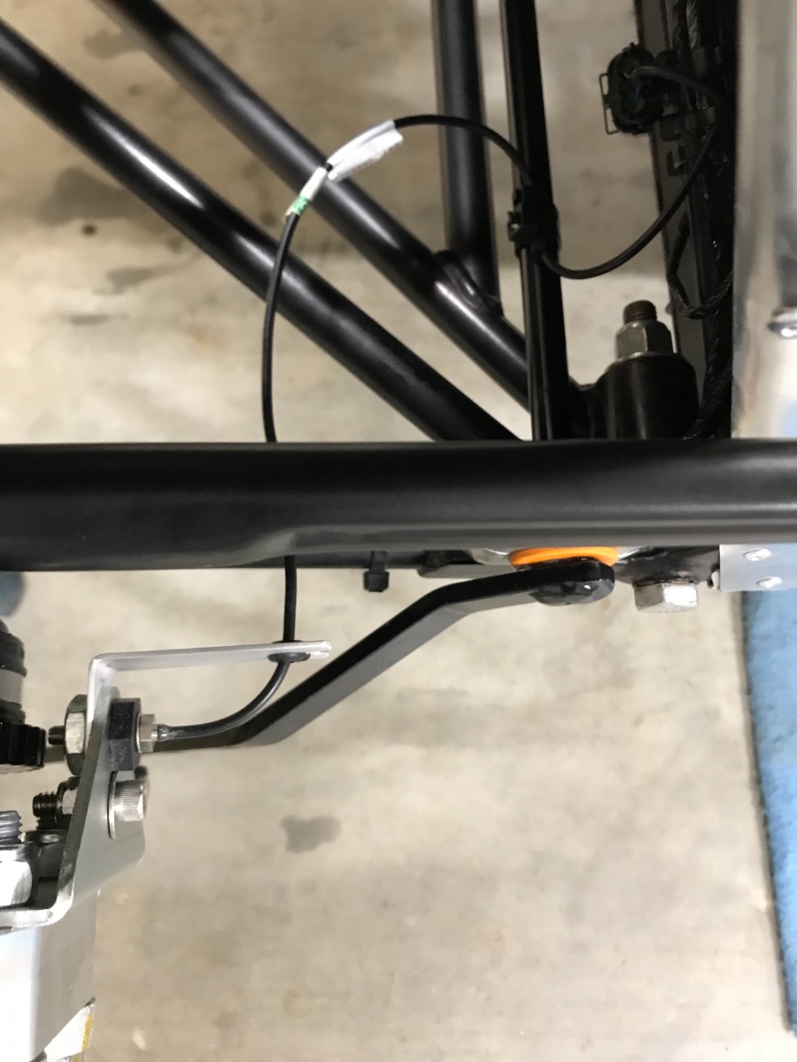
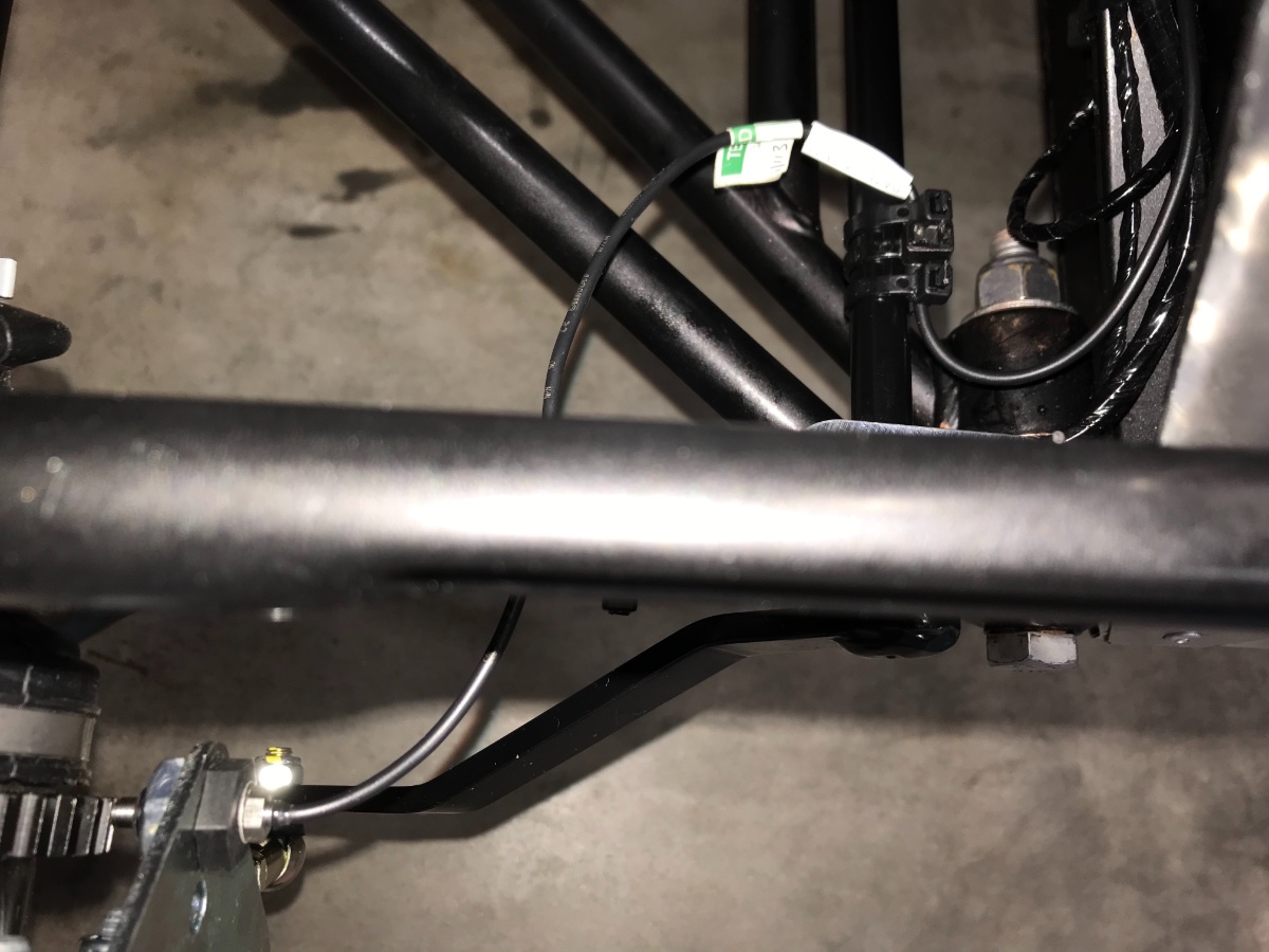
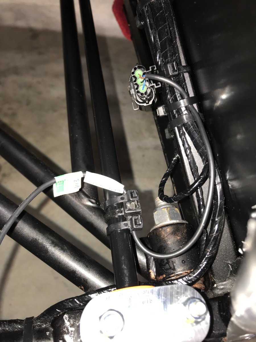
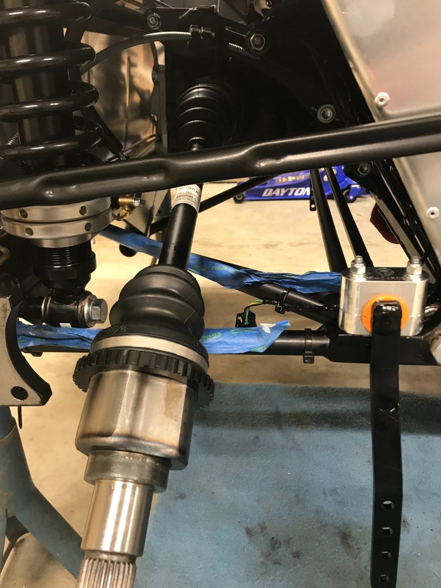
Speed Sensor Today was a short "play" day but trying to stay current I'm filing a brief report on installing the speed sensor. The mounting design is differnt vs. what is documented in either guide but straightforward enough. The main task for me was proper routing of the wiring. I ended up routing a bit differently vs. Chris Collins and the guides. I "un-zip tied" the chassis side wiring from the bottom tube and connected both ends by the connector to assess overall length and routing options. The connector has a mounting "frame" which allows to zip-tie it to a base. I ended up attaching it up the rear bulkhead diagonal tube. Coming from the sensor I routed the wire inboard, then back outwards along the ARB and zip-tied it in a rubber sleeve to the ARB a few inches from the bushing. Once past the attachment to the ARB the routing makes a U turn and up the diagonal to the connector. This keeps the wire inboard and away from the wheel, allows gentle articulation on the ARB and leaves the radius link clean. I think this should work. I did not implement Chris Collins' "local" grounding - will do down the road if needed. View from above View from above, connector visible at top of pic. (copper grease residue will get cleaned up, promise...) Side view Cheers!
-
Thanks! Will keep in mind for next build...
-
Rear Anti-Roll Bar - Axial Play Solution I mentioned earlier that I had 5mm free axial play of the ARB and that it bothered me. I decided to try to come up with some nylon shims on each side between the bushing and arm to take almost all the slack. The shims I'm using are based on nylon washers I found at Ace Hardware, 12.8mm ID, 19.1mm OD, 1.5mm thick. I split each washer radially in one spot with a box cutter. I unbolted the bushing blocks from the chassis and slid inboard on the bar to make room for shim installation. Lubed each shim with silicone grease and mounted on the bar outboard of the bushing by opening the split shim like a key ring. Total play was 5 mm so I needed 3 shims. Measured on each side the distance from ARB bracket on ear to chassis tube -- got 89.2mm LH and 87.6mm RH, therefore installed 2 LH shims and 1 RH shim. I can feel barely any ARB axial movement now. It will be interesting to see how these hold up along with my split bushings... Shims LH shims installation (bushing block slid inboard to make room) RH shim installation LH side buttoned up. RH side buttoned up. Cheers!
-
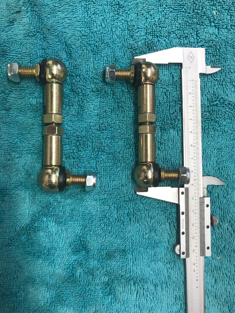
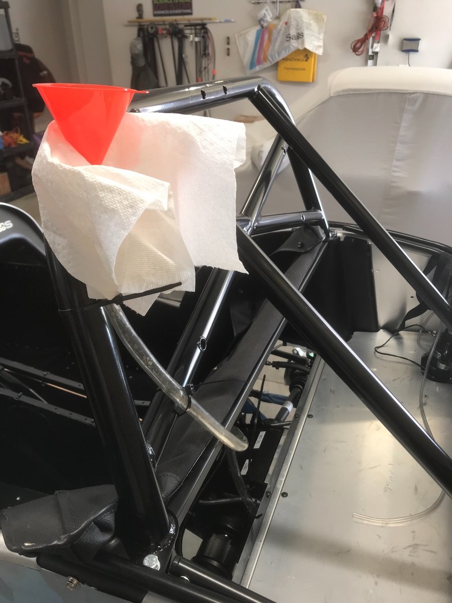
Rear Axle / Suspension continued..... Ears Blew inside De Dion tube with compressed air and sprayed with WD40 against corrosion. Coated tube flanges with SuperLub 82003 anti-corrosion gel. Installed ears over driveshafts onto tube flanges. Bearings Coated bearing flanges as well as driveshaft bearing interface with SuperLub 82003 anti-corrosion gel. To get the bearing ID onto the mating driveshaft OD required some gentle taps with a mallet on a block of wood around the bearing face. Once past the initial engagement point they slid on smoothly. Ear Washers!!! Major confusion re washers for middle and front ear bolts/nuts -- IKEA guide, 2015 "text" guide and I Pack "BOM" info inconsistent. Ended up Installing no washers under middle and front ear bolt locknuts: Washers under middle bolt locknuts, especially the bottom ones, may interfere with the tube flange weld -- cannot use washers in that position. No need for washers at ARB brackets. Ear bolt torquing!! Torquing is done on the bolts due to difficult or impossible access to the nuts (and no nuts on rear bolts). Bolt heads are shallow and require torque wrench socket extension. Difficult to do solo (need 2 hands to keep the torque wrench straight + a hand for counter torque...) ARB drop links Adjusted to minimum and equal length (93 mm). Installed and torqued. No issues. Diff Fill I have the optional LSD. Using Castrol Transmax Limited Slip 75W140. Gravity feed using funnel and hose attached to roll over bar, and easy hose routing to the fill hole with trunk wood board removed. No issues unscrewing fill plug with 14mm hex bit. Minor snag: Instructions call for 0.8L but 2 x 0.5L bottles used with no fill oil reaching hole -- ordered a 3rd 0.5L bottle. (These are not available locally so may want to order 3 x 0.5L upfront and save shipping costs.) Note: Remember to make sure car is level before oil fill - needed to lower the front jack stand to level the car. That's as far as I got as of now. Immediate next tasks will be complete the diff fill, bolt the propshaft to the diff, sort out the ARB lateral play (I have an idea I need to test), install the speed sensor, install the brakes and partly torque the driveshafts. Re the last one, awaiting a LH nut (received 2 RH ones...). Lesson here is confirm LH & RH nuts earlier to avoid the wait. As always I welcome all inputs, critique and tips (monetary as well). Cheers! Yoram
-
Well... a Caterham is pretty unusual on this (and that) side of the pond, huh? Cheers!
-
(topic is driveshaft installation into diff) Yes, I share your exact concerns. No, unfortunately I did not take a pic of the inner splines, but I pulled one back out before installing the ears, looked carefully and saw no circlip or groove or any other feature. Investigated a bit more and found no mention anywhere of the clip or locking feature. What I found was: 1. 2015 "text" guide: "Insert the unthreaded end of the driveshaft into the differential taking care not to damage the seals in the differential. The longer driveshaft is fitted to the RH side. The shorter driveshaft is fitted to the LH side. To aid insertion, lightly grease the splines of the driveshaft and if necessary gently tap the outer end of the driveshaft with a soft faced hammer. Ensure that the driveshaft is held as straight as possible to prevent damage to the boot." 2. Chris Collins blog: "Now just remove the bung from the differential and insert the driveshaft, it should be as simple as that.". 3. IKEA guide (which I know is not the most detailed): See pic below. No circlip shown and no mention in notes. 4. Asked my Guru Josh Robbins from RMC about this and his reply was (I hope he doesn't mind me quoting him without permission...): "Yep, you should be able to seat the driveshaft splines just by pushing in by hand -- simply a matter of lining up the splines. However, they may leak at this point if the diff is filled. Once the rest of the rear suspension is assembled and the hubs/ears are securing the outboard ends of the drive shafts, there will be enough force on the driveshafts (in the compression direction) to push the driveshafts enough into the diff lip seals and make them oiltight." I tried moving the inner CV joint housings axially by hand in either direction now and they don't move. Got to be careful not to damage the boot. If anyone has more info or other ideas about this please advise ASAP, before I install the brakes...
-
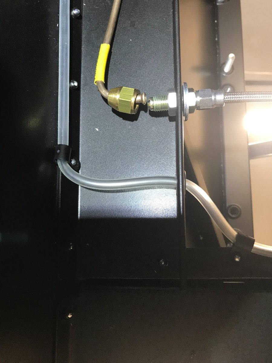
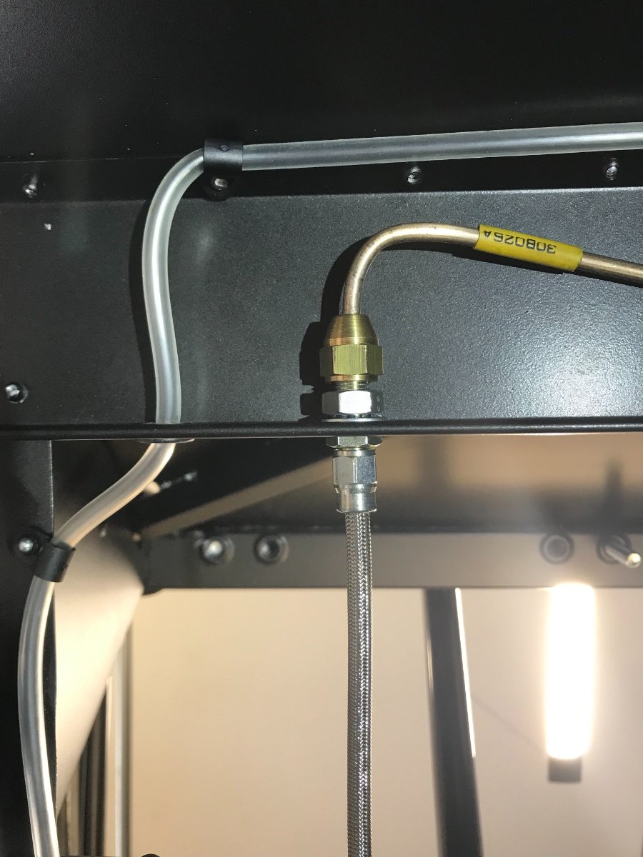
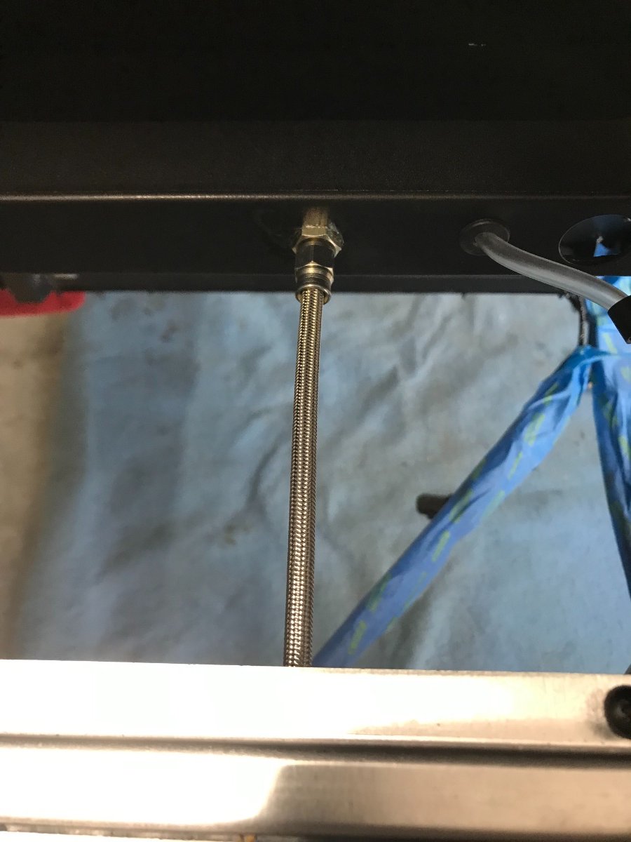
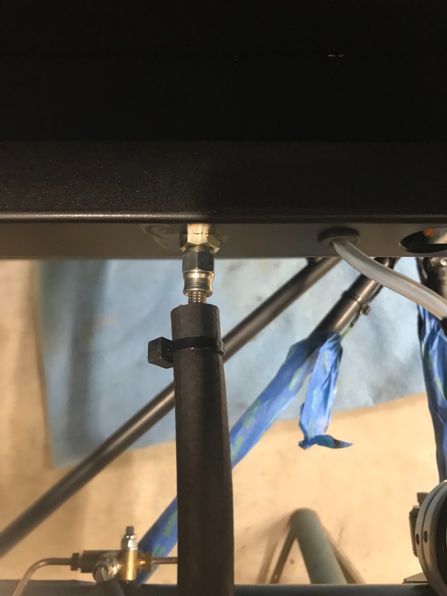
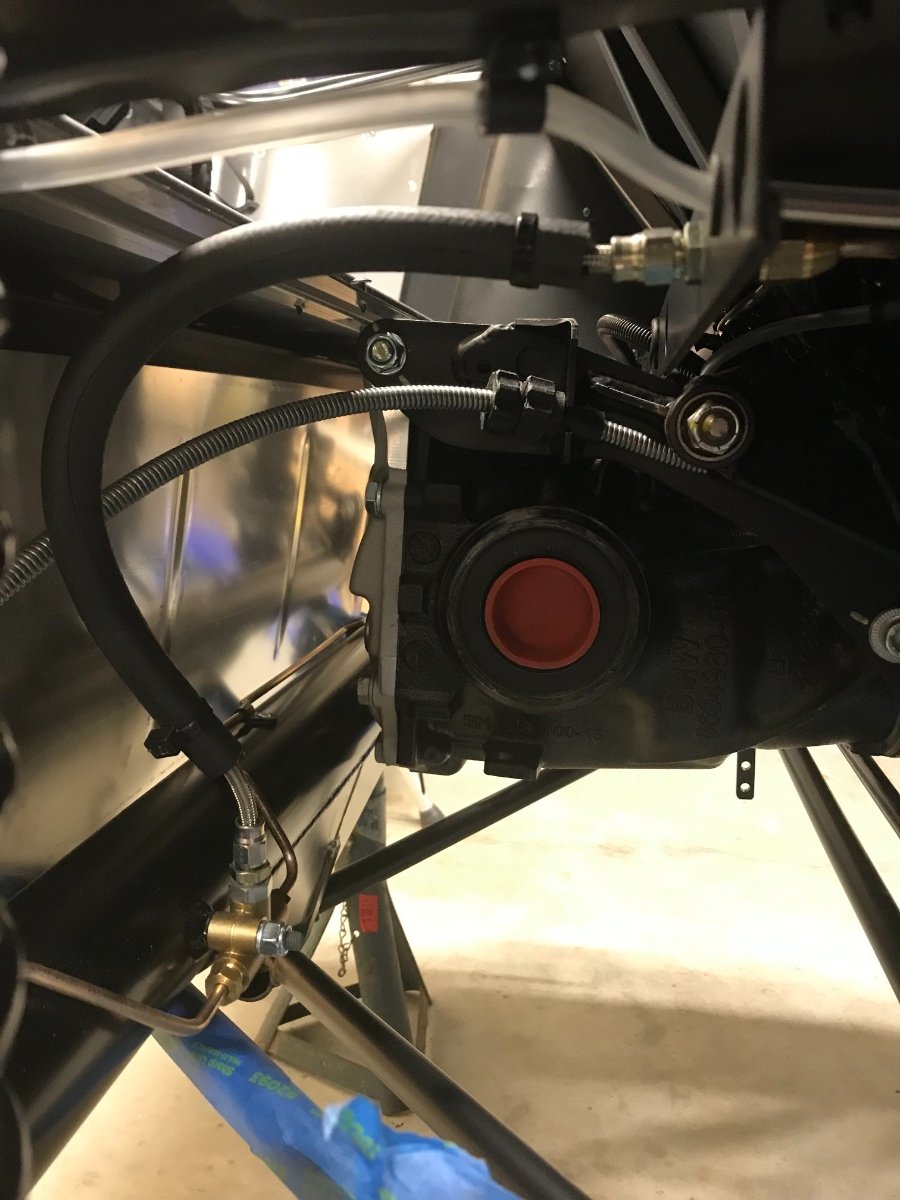
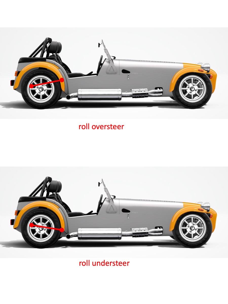
Update: Rear Axle and Suspension Overview of where we stand now: Brake lines, De Dion tube, coil-overs, radius arms, A-frame, anti-roll bar (ARB), driveshafts, ears, bearings and drop-links installed. Ear, ARB and drop-link fasteners torqued. Diff *mostly* filled (of which later...) Highlights and Lowlights Braided brake hose connection to fitting and brake line on chassis: Copper brake line (pre-assembled on frame) was misaligned with hole in frame for braided hose fitting. Not enough line length was available to align the end with the fitting in the hole. Needed to enlarge the hole laterally to ensure square alignment before connecting fitting. Smoothed the hole with Dremel tool and and touched up with chassis paint pen. Before and after hole enlargement View from above after installation (trunk wood board removed). Lessons: 1. Prior to diff installation check ability to align the copper brake line routed from the tunnel with the fitting attachment hole on the frame. Should be possible to loosen and adjust routing in frame to ensure alignment without modifying the hole; not accessible once diff in place. 2. Install the fitting to the copper tube and the hole in frame finger tight making sure perpendicular to frame before tightening. Braided hose protection (split rubber hose): Radius Links: My car is an S, not an R, however after some pondering and consultation with Denver I decided to attach the radius links at the lower points on the body designated for R and Academy cars. The lower attachment should bring less roll oversteer or more roll understeer as shown in the following schematic: A-Frame: Installed ensuring centering: 89.5 mm on LH side and 88.6 mm on RH side from face of De Dion tube flange to outer surface of chassis tube. Used 4 chamfered shims on the LH side and 3 on the RH side. Outer shim chamfers in each stack face outboard. No special issues using similar technique to diff install. Anti-Roll Bar: I did not like the idea of pulling and stretching the bushings over the ARB arm weldments per the instructions, so I assembled them onto the bar by filleting each bushing lengthwise on one side with a box cutter and orienting the slit horizontally on the bar. The bushings are contained by the housings and the bar and have nowhere to go. If I encounter issues, which I doubt, it should not be too difficult to replace them. Lubricated the bushing ID with silicone grease (not the OD). Installed ARB into frame and torqued. The bar rotates freely in the bushings. I don't like the fact that it has axial free play of about 5 mm. I am looking into it and will report resolution. ARB shown shifted all the way left. The slit can also be seen pointing back (to the right of the pic). Driveshafts Lubed inner splines and sealing surfaces with diff oil and inserted in diff. No issued but a bit disconcerting that they do not have a positive locking feature (e.g., circlip) inside the diff. View from above at diff after installation of ears and wheel bearings: _______________________________________________________________ Continued below in another post (out of pic file size). Cheers!