jevs
-
Posts
316 -
Joined
Content Type
Profiles
Forums
Store
Articles
Gallery
Events
Library
Everything posted by jevs
-
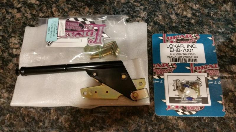
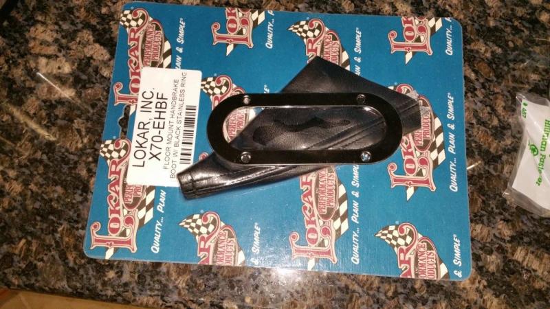
I received all of my parking brake parts. I will need to order the cables once I figure out how long they need to be. From Summit (I highly recommend getting them to price match. They matched reputable eBay seller for a nice savings). XEHB7000F Lokar Emergency Hand BrakeBrake, Midnight, Black Powdercoat Steel, Floor Mount, 11.5 in. Handle EHB-7001 Lokar Emergency Brake Warning Indicator Switch Kit X70EHBF Lokar Emergency Hand Brake Boot, Black Naugahyde Boot, Floor Mount, Includes Black Boot Ring From IPSCO IPS080-R Mechanical Parking Brake Caliper - Right Hand Pull (Made for 24mm thick rotor) IPS080-L Mechanical Parking Brake Caliper - Left Hand Pull (Made for 24mm thick rotor) IPS080-BK Optional Caliper Mount Bracket Set IPS080-CB1 Optional Cable Bracket Set (Modified with 1/2"-20 threaded hole) From controlcables.com BEQ-EZ-2 Emergency Brake Equalizer Bar B-E-2-8 Bolt On Brake Bracket (DOUBLE) 1/2 Hole The IPSCO calipers are nicely made. They shipped quick. I looked high and low and the only other viable option I found were from Hispec that would fit this wide of a rotor and they took too long to get me the specs. Their website was not working right. I had already ordered the IPSCO. However, if your researching, you may want to check those out also. I will have the cables made by controlcables.com when I figure out what length. I am hoping having them made might actually be cheaper than the universal style. The other advantage is that nothing has set screws into the cable and I won't have to modify them myself. The down side is that you have to get them the right length in one try and you won't have the actual cable to use to figure it out.

-
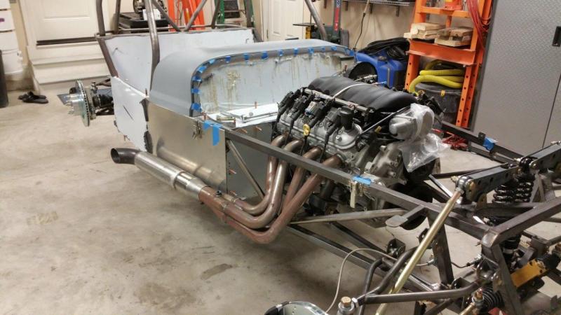
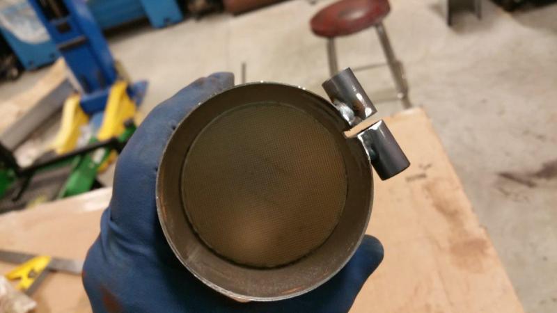
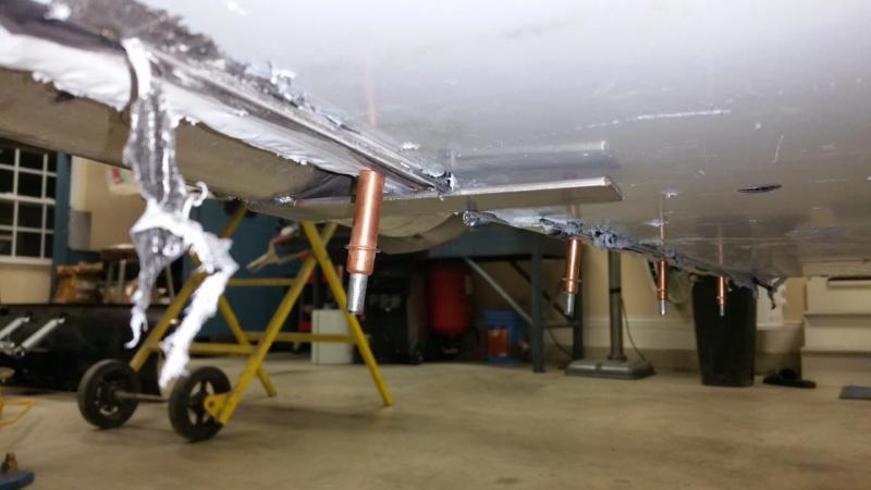
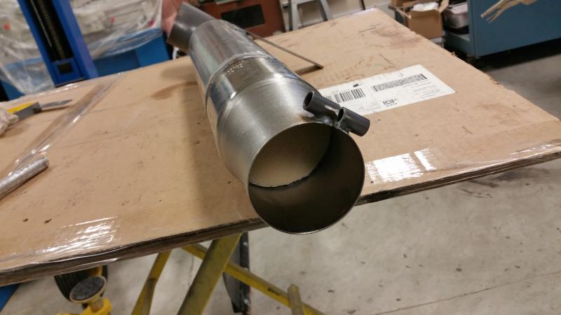
Started working on the exhaust. The headers went on with no issues. The stock bolts are being reused. The ones that came with the headers are not as good. From the pictures I found, Brunton also uses the stock bolts. I used the stock gaskets that came off the crate motor just to protect the head. I will use the gaskets that came with the headers on final assembly. The side pipes are turning into a little but more of a challenge. I was told to try for 1/2" gap between the body and the muffler. This is no problem on the drivers side. The passenger side naturally hanging wants to be very close to the body, but I think I will be able to finesse it out. The bigger issue I have with the side pipes is the mounting method. The strap is just supposed to bolt through the aluminum floor and use a piece of hose as a rubber washer I guess. I am worried this will cause problems after some time of use. I am going to try to come up with a better isolated mount and try to keep the hardware from being much below the floor. I know a lot of guys have issues with side pipes on other cars and I want to minimize those headaches before they occur, if they would even occur. I don't know if or when it could cause a leak or crack, but I know it can be better, so might as well do it now. I started another thread on it just to keep this one more about the actual build than figuring stuff and brainstorming ideas. http://www.usa7s.net/vb/showthread.php?10339-Side-exhaust-mounts The side pipes do appear to have small cats in them if anyone was wondering. No hardware came for the clamps. I purchased some stainless 2.5" 3/8-16 bolts and nylock nuts. I will put anti-seize on them during final assembly to lessen the chance that they will gall up and need to be cut off if ever removed.
-
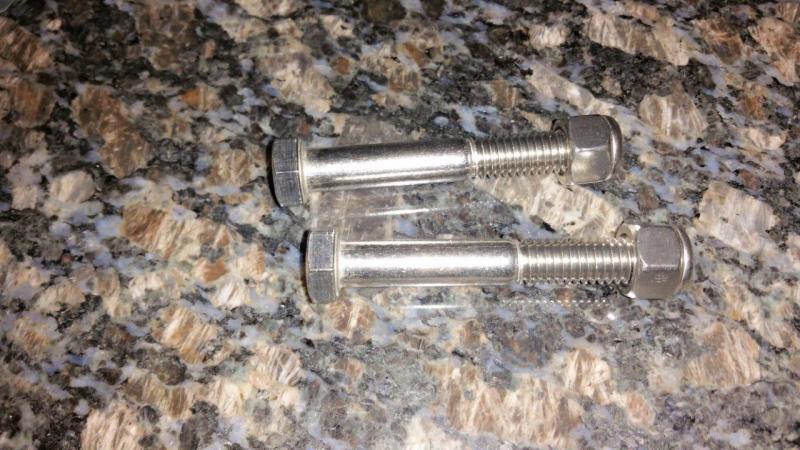
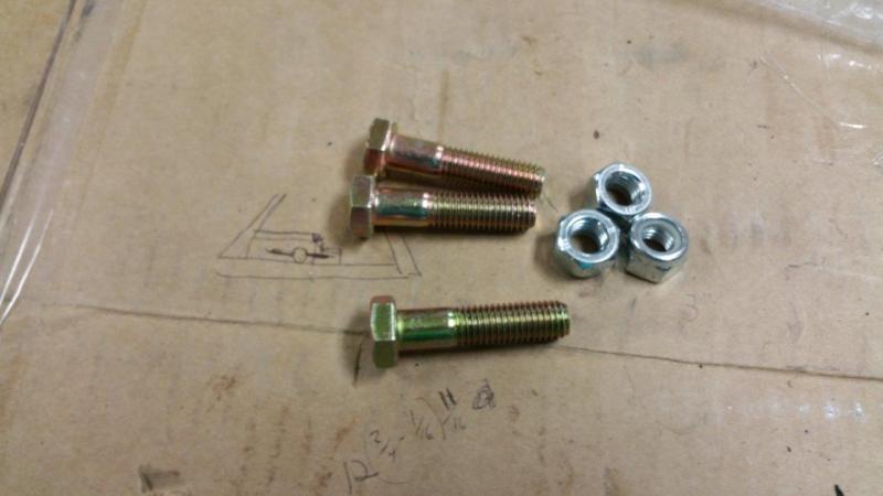
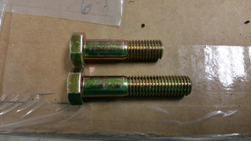
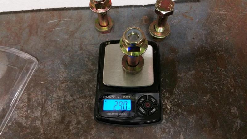
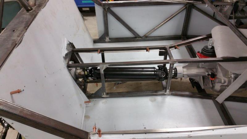
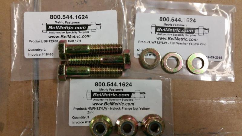
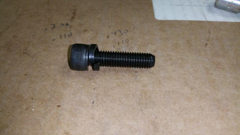
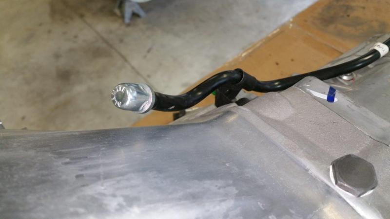
I had the same issue with the bolts for the driveshaft as toedrag. The head interferes with the U joint because they are too long. The first picture is what you get with the kit. The second picture is what I bought instead. Since I was going to have to cut the bolts anyway, I went ahead and got some with a longer shoulder so it would have more shoulder in the differential flange. Not necessarily needed, but I was ordering some other stuff from BelMetric anyway. I also added washers under the heads and purchased flanged grade 8 nylock nuts. BH12X60 - 12mm x 60mm Bolts WF12YLW - 12mm Washers NNFH12YLW - Nylock Flange Nuts I cut them down and then weighed the assemblies for the heck of it. Only one was .01 oz. off from the others, so I shaved a little off and they are right on. I doubt this was necessary, but what the heck it was only a few minutes. Everything went in and bolted together fine once the bolts were modified. You can put the driveshaft in from the top if you want.
-
I ordered 2 of these to experiment with (4 mounts total): JEGS Performance Products 309025 Snap Grommets http://www.jegs.com/i/JEGS+Performance+Products/555/309025/10002/-1 $12.97 shipped And 4 of these to experiment with: GEX7251 Exhaust Mount Rear Bobbin - Mini And Mini Cooper S http://www.minimania.com/part/GEX7251/Exhaust-Mount-Rear-Bobbin---Mini-And-Mini-Cooper-S $13.00 shipped I think the rubber ones are going to end up being better to let the system flex more, but I wanted to get both to see. I did do a bunch of reading last night. A lot of Cobra guys have experienced side pipe issues and there are a ton of not so good methods out there for attaching them. They do have more room and more ways to hide the setup though. The better methods I saw would not really work on my car since the bottom is flat and no where to tuck stuff up.
-
Found a link mounting the way I need to using two of the snapper style: http://i0.wp.com/www.welderseries.com/blog/wp-content/uploads/shopp/images/10308177_680854675305212_8058138231106402790_n.jpg
-
I have just been thinking of ways to use that snapper style. All the prefab ones like that are not in the right orientation that I have found so far. It needs to be more in the orientation like a motorcycle exhaust hanger is....I can make that though. I am going to check around locally in the morning to see if I can find some snapper style hangers, if not, I will order some. They are cheap, I just hate to wait on them. I think I might be able to do something with those that looks better than the bobbin style.
-
Is there any isolation in that configuration?
-
Do you have a picture of what you have now? I already wasted two nights thinking about this and all day during work. I think it is about time to concede and cut the current bracket off and start from scratch.....sigh, more fab work. I will never get this thing done
-
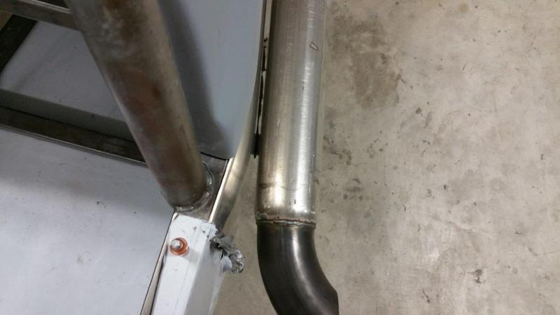
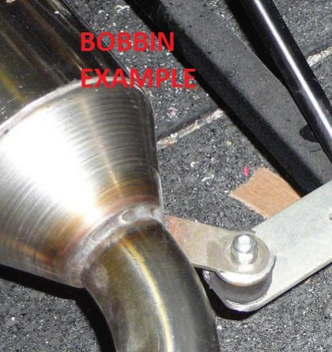
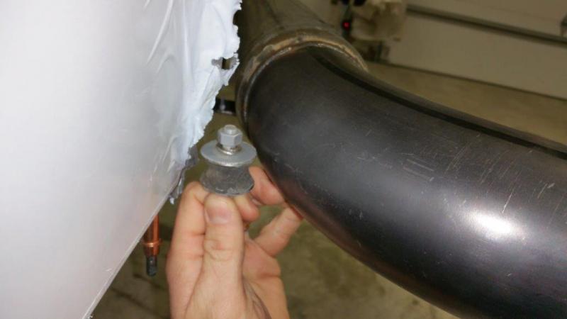
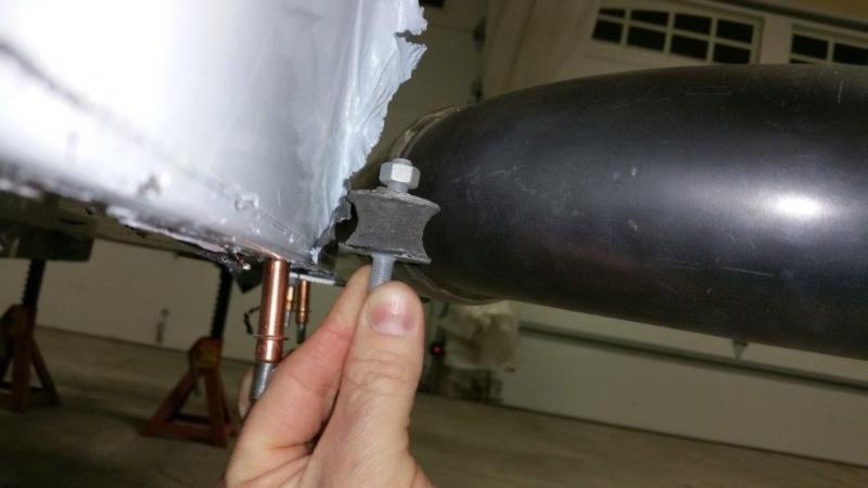
This is what I got with the kit. I was hoping not to have to cut it off and re-invent it The bobbin style seems like it would work pretty well, kind of like this (see pic of example), but this is totally different than what I have to work with now. I happen to have an old dry rotted one of those bobbins I saved. I must have known this day was coming.... You can see it won't fit where the strap is now. I would have to do some welding, but it could be located farther back where it will fit.
-
How do you think those would work bolted flat to the floor with the strap horizontal (flat)? Oh, and I found some cheaper here and they are suppose to be a "Super High Temp" (blue ones that are not shown). http://www.welderseries.com/blog/online-store/exhaust-grommet/ Another thing to note, that whatever is done here will be hanging below the floor pan....so getting very big is also an issue.......unless you consider how far down the oil pan is
-
How are those attached and isolated underneath? I don't need any clamps. I just need to properly mount the horizontal strap to the floor with proper isolation.
-
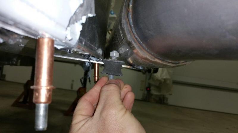
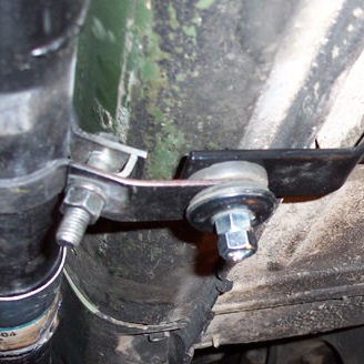
I was looking around and found this. I think if the bracket was sandwiched between two rubber pads like this, that might be good enough. Just making sure the bracket hole is slightly bigger than the bolt so it can rock a tad without the bolt needing to move. I think this is what I will do.... Edit....not sure I like this, the more I think about it. It is not going to be truly isolated and will have to hang under the car over an inch by the time you get a fastener on it etc.
-
Looking for some pictures and part numbers of what you did to mount your side exhaust. Mine just has a blank flat strap coming horizontally off the bottom of the exhaust that is suppose to bolt to the floor. Your supposed to make a rubber washer out of a hose to go between this tab and the floor. I have a couple issues. One is that my side panels required a spacer between the floor panel and the lower lip to make them a tight fit. This brings it down a little and the exhaust tab has a little extra to clear there. I can either trim this away in the tab area, or just mod the flat bracket a little. Another option would be to change to a side hanging setup instead of a bottom mount. I just wonder if a rubber washer will let the exhaust move enough? It still has a metal mechanical connection with a nut and bolt through all of it as opposed to an actual rubber isolator. Anyone have this style of exhaust to show what they did and some testimony on how it is holding up over time as far as leaks, header leaks, cracks, etc.?
-
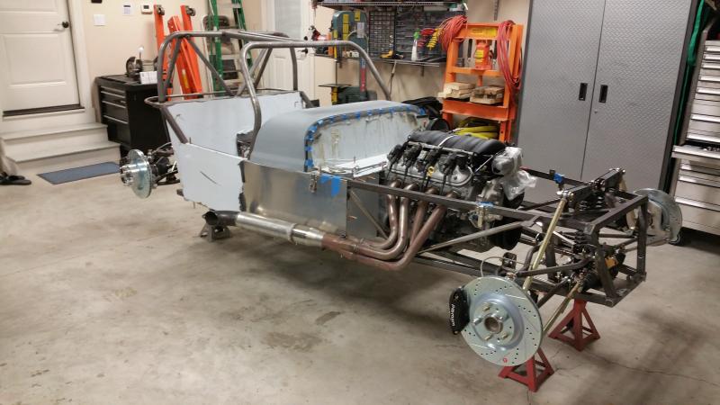
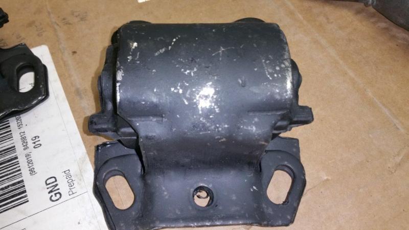
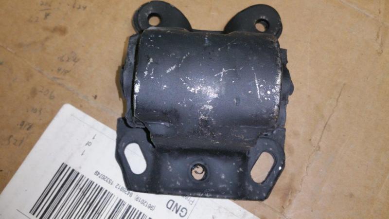
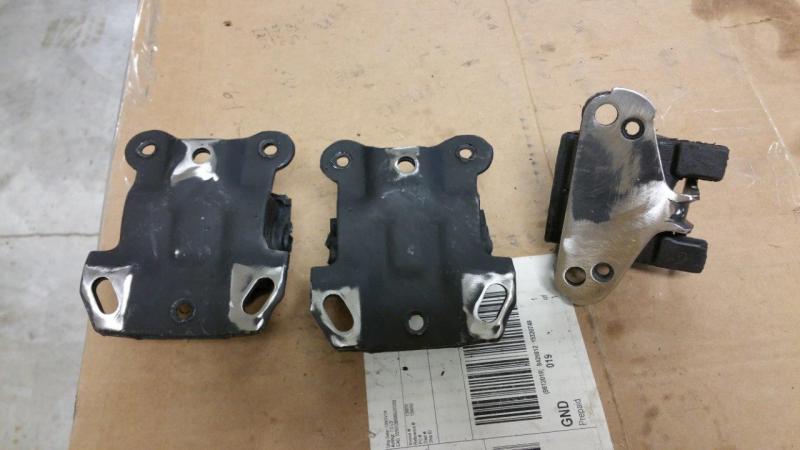
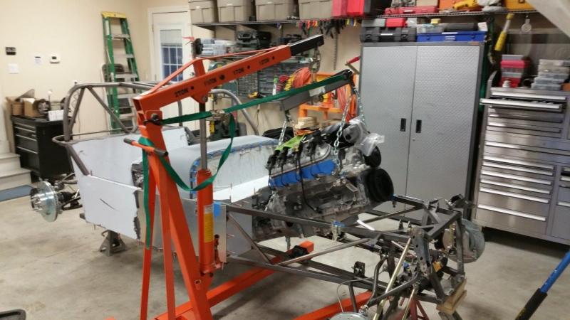
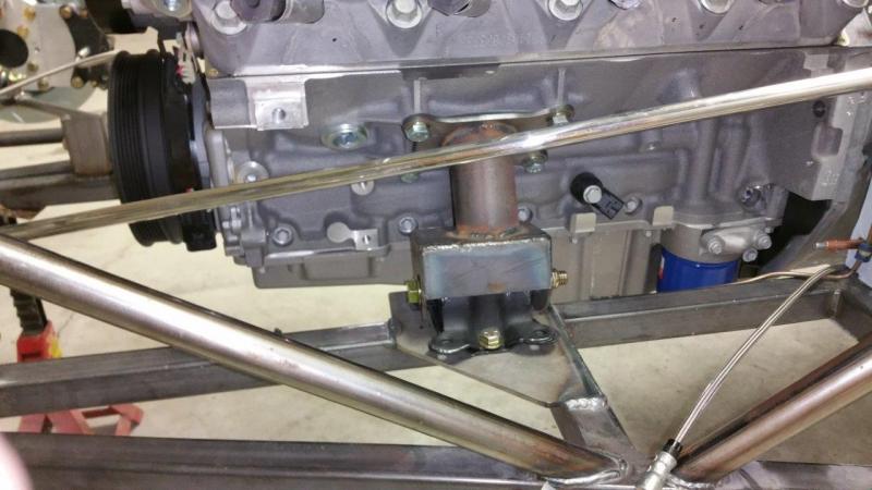
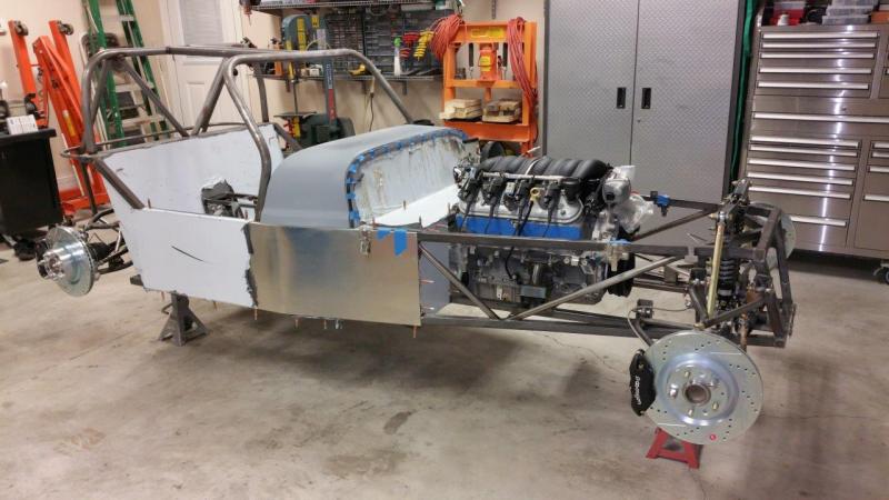
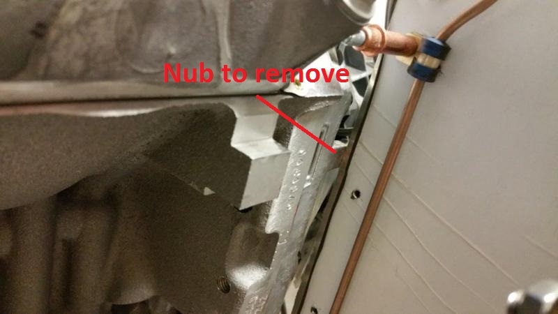
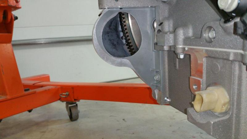
The motor mounts I got are the exact brand and PN as the ones in the Brunton video. I guess it is luck of the draw, but I did have to grind off the ears on mine. I also think the punch press they use for the mounting holes wore out about 10 years ago. I recommend grinding the bottom of the mounts to git rid of the big burrs. These will keep the mounts from sliding around for easy positioning and gouge the heck out of your finish on final assembly. I also trimmed the transmission mount flanges as per the Brunton video. This has to be done for the T56 Magnum. The motor went in no problem. You do not have to remove the steering shaft. The video recommends removing the brake lines in the front at the T fitting, but I don't think that would have been needed for the XL. There is tons of room in front of the motor. I did not follow the instructions on the video for trimming the nub off the bell housing because they were putting it in a regular M-spec and I saw on some picture I took of an XL that it still had the nub. Well, as luck would have it, it turns out the nub had to be trimmed. It was touching. Luckily I was able to just undo the motor mounts and swing the motor over enough to trim it. There is only around 1/8" or a little better of clearance on the drivers side in a couple spots.
-
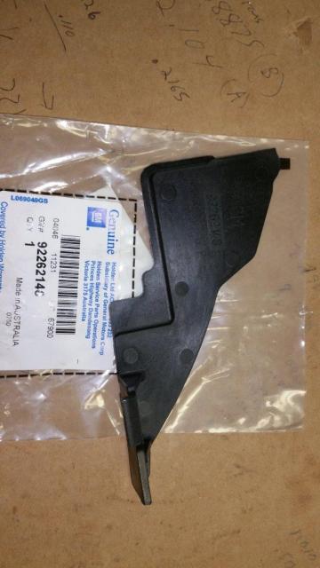
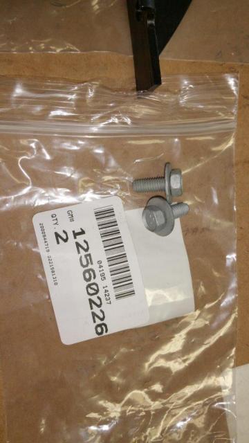
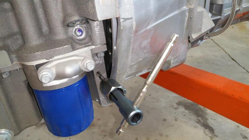
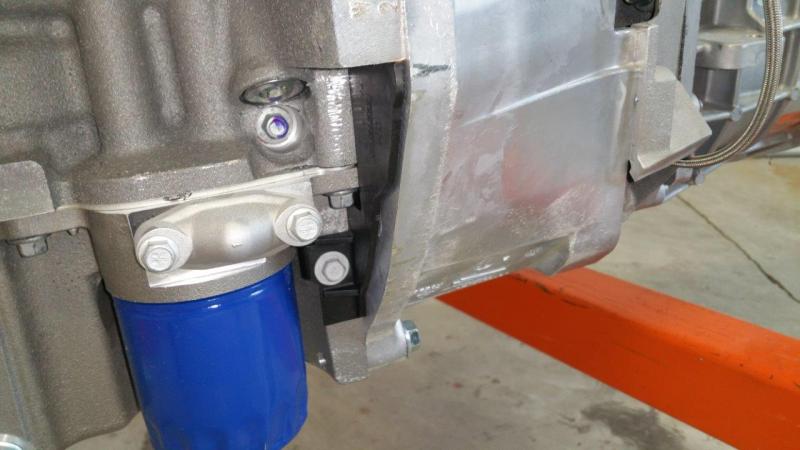
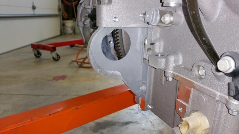
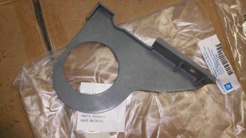
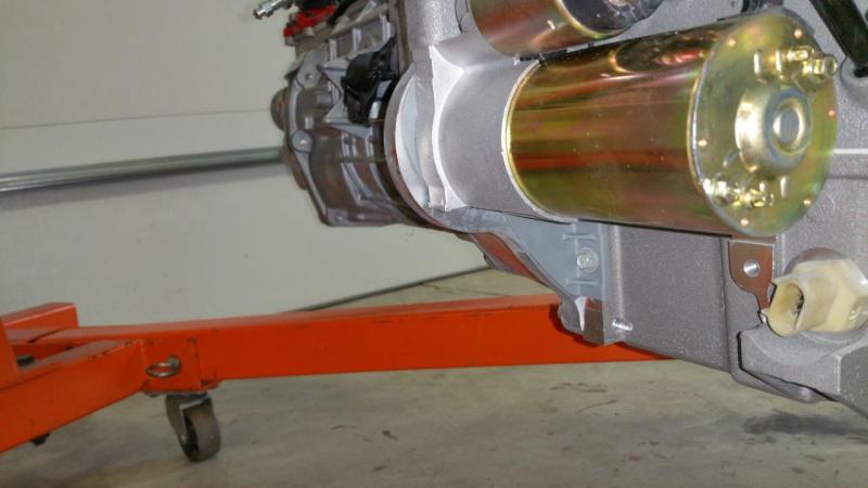
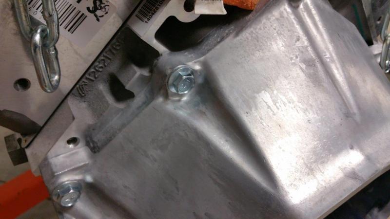
I ordered covers for the right and left side of the bell housing. Brunton does not use these, but I wanted to put them on just to keep crud out. It was a bit of a guessing game on which ones would work. I ordered 92262148 for the drivers side. It fits good and with no issues. You do have to tap the holes 6mmx1 on both sides. They come drilled the correct size, but untapped. I did some calling around awhile back and got the right part number for the bolts that hold the covers. I am kind of a stickler for using the OEM bolt when I can. The part number for this is 12560226. You can see they have an over size built in washer that helps to not damage the plastic when tightening them down. For the starter side, I ordered part 92169247. This one required trimming of the hole to fit my starter. Maybe the one toedrag bought may fit with no trimming, I am not sure? Either way, it is not a big deal to trim it, but bolting on with no mod may be preferred. http://www.usa7s.net/vb/showthread.php?9868-Brunton-Stalker-XL-22-Build&p=90446#post90446 I test fit the starter, but took it back off for the motor install.
-
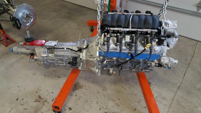
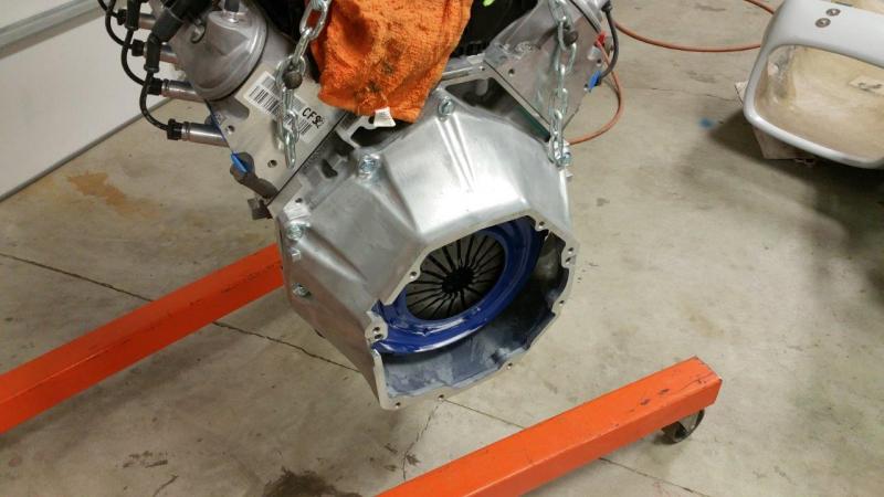
The bell housing to transmission allen head bolts came with the bell housing and transmission. I did not get them at first, but then they sent them after I called. They use a real thick lock washer. I bent the breather tube bracket just a little so that the tube and breather had plenty of room. The way it was at first it would have been vibrating against the transmission possibly making an annoying noise later. The transmission and motor went together like butter.
-
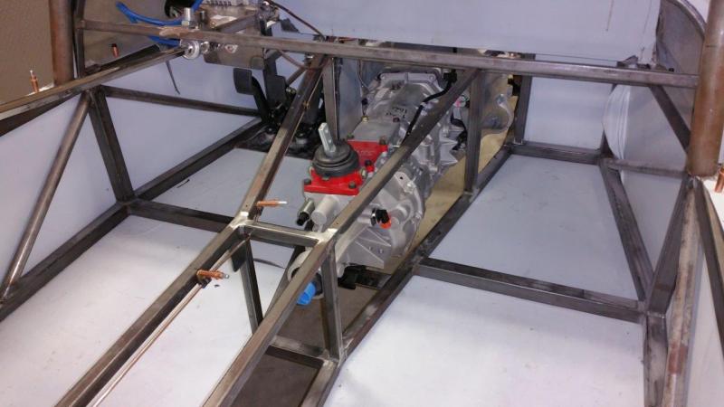
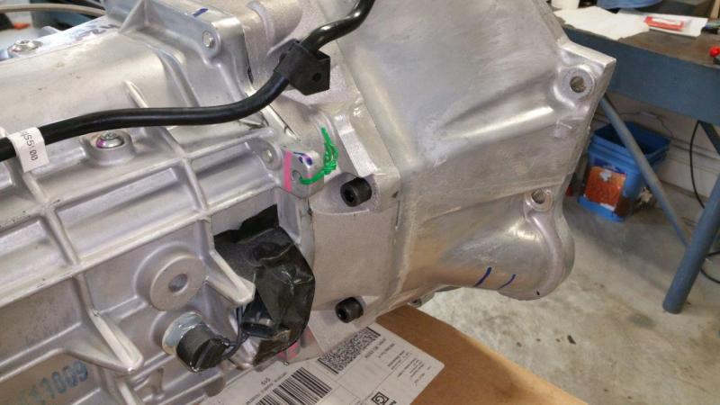
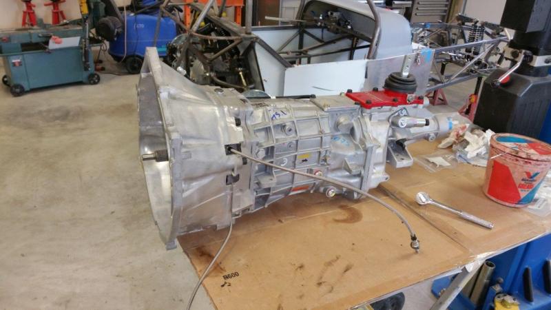
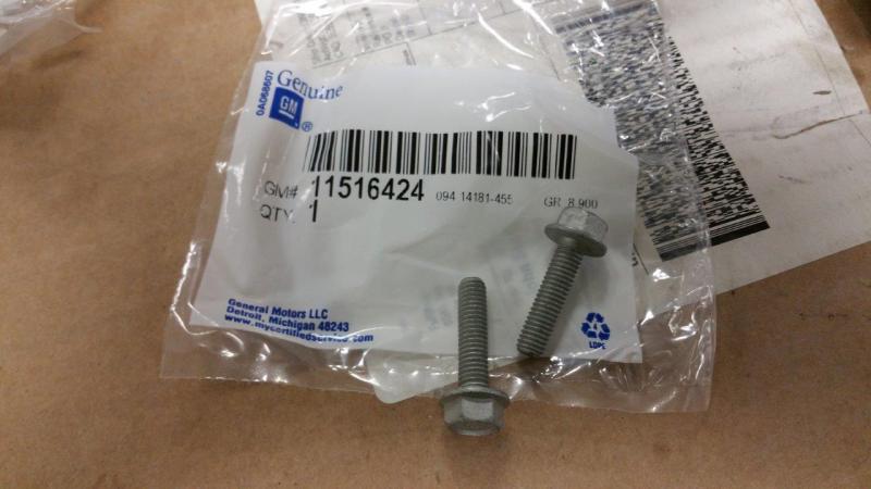
And here is all that stuff bolted on the transmission. I used OEM bolts for the slave cylinder. The part number is 11516424.
-
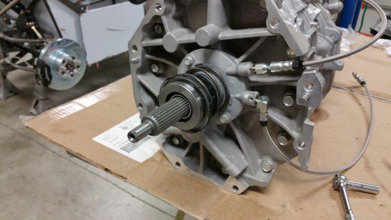
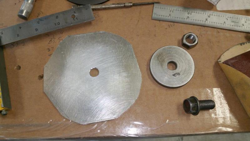
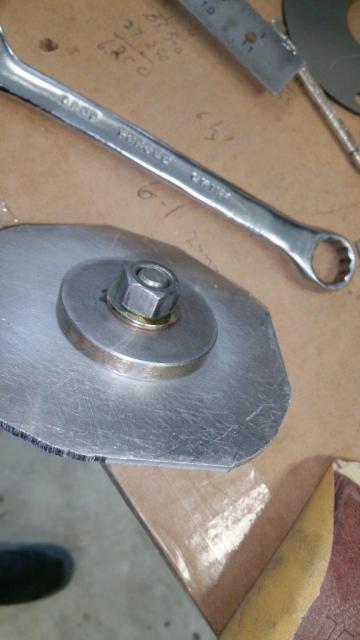
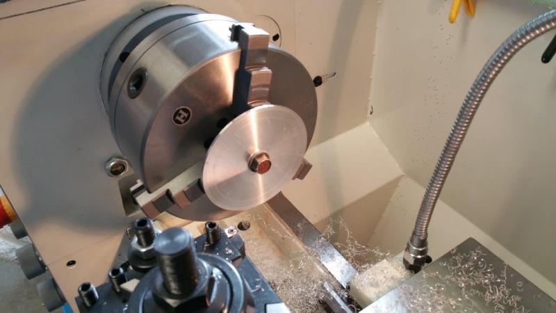
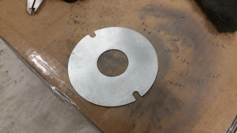
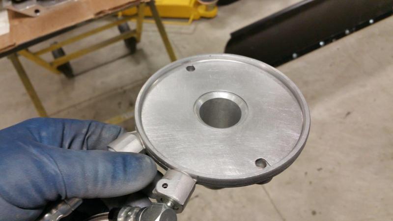
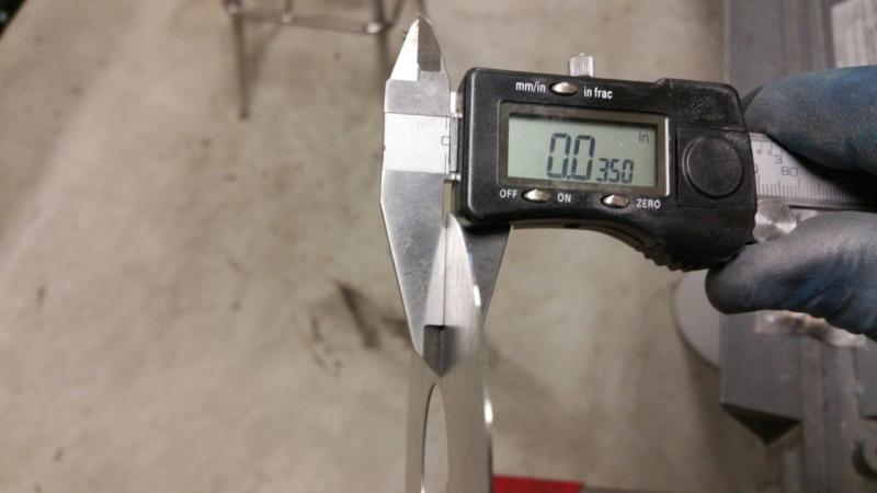
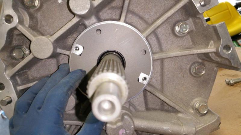
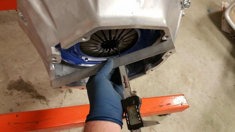
I found some suitable aluminum plate in my metal bin. I just hacked it off in the horizontal position of my band saw real quick so it was kind of roundish. The hard part was figuring out a good way to hold it so I could still machine it. I ended up drilling a hole and using a machined spacer I had laying around. I bolted this spacer to my plate and grabbed that with the lathe. I then faced off the first side. By the way this was a good excuse to play with my new lathe I don't think I could go without a DRO now. I had to do some various trick to be able to hold the part as I processed it. Once I got the other side down pretty far, it was getting thin and a bit flexy and chattering some. I got it as close as I could and then cut the OD and bored the center hole. I did find that one of the faces of my chuck jaw was about .002" lower than the others. This made worse chatter due to the gap there. I am going to find out if this is in spec or not and get a replacement if it isn't (Chinese stuff for you ...sigh) Due to the flexing, I spent quite a bit of time sanding and measuring and perfecting the thickness by hand with various sanding blocks and grits etc. I got it all within .001" or less with a target of .0350". You can see that it hugs the bolts much nicer now. I put the spacer in and made multiple measurements and averaged them. I now have a result that is .1882". I am very happy with that. My slave won't have to come out too far before it starts pressurizing and I have enough room for the disc to get used up without getting preload before it is worn out. Long day just to make a spacer, but no one sells one this size anyway that I could find.
-
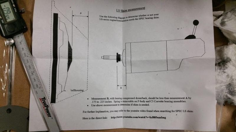
The purpose of these measurements is to make sure you have room for the throw out bearing to compress and still have clearance when the clutch is engaged and also to make sure the throw out bearing does not require too much pedal movement before it releases the clutch. The best thing to do is to take multiple measurements in different spots and on the clutch side to different fingers also. Take these results and average them and then subtract averaged B (trans side) from averaged A (engine side) to get the difference. I ended up at .2208". However, some spots would be lower and some spots higher before the averaging. According to the instructions, this is good for no spacer (if you ignore that some of the averaged in distances would be slightly higher on their own). According to the SPEC clutch instructions, the distance should be .175"-.225". If your lower than .175, then you have a problem that a spacer cannot solve. One thing I found that confused matters more is that the video link they give you on the same paper says .250 is the max. I called SPEC and they would not really give me a concrete answer. It was like "it's your car, you have to decide, we don't want to be responsible". We did agree that I had two options...no spacer, or get a different spacer. The spacer they give is about .116" thick and this puts you way outside on the low range, so it cannot be used. It would be ok at first, but at some point as the clutch wears, you will end up with preload. As the clutch wears, the pressure plate fingers move closer to the transmission and reduce this gap your measuring. Here is that video I did not like being on the edge of the tolerance and they would not tell me it would really work well up to .250 like the video says. I also did some research and found that other clutch manufacturers do not spec this high. So, since I cannot use their spacer and I was on the edge, I decided to machine my own spacer and just put it where I want it. By the way, the Brunton install video recommends to put the spacer in. I would say measure your specific setup to make sure. I know toedrag and I both got measurements in the "no spacer" range. I was just too far on one end for my liking. Another benefit of making my own spacer is that the one SPEC gives you has large square notches. This leaves a lot of area around the bolt unsupported. Picture of theirs attached.
-
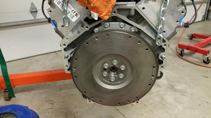
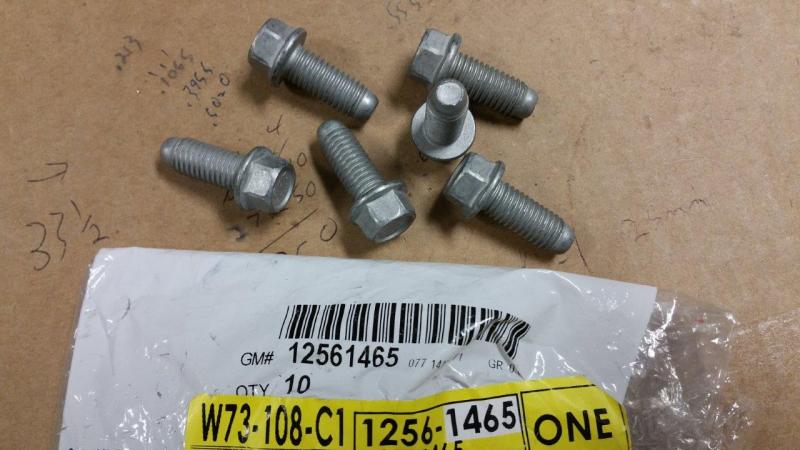
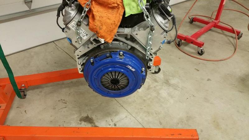
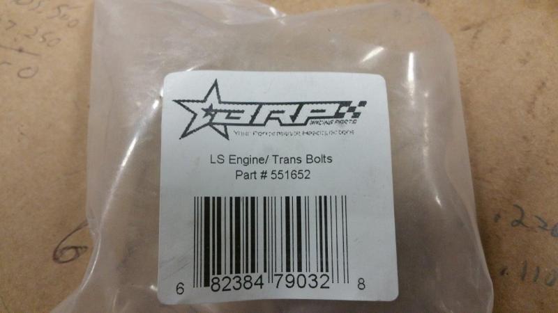
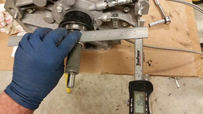
Bolted the flywheel on using the OEM bolts that came in the flex plate. A flex plate or flywheel use the same bolts on these. I bought OEM bolts for the clutch pressure plate. Part number 12561465. I had to bolt the bell housing to the motor in order to measure the distance to the pressure plate fingers to see what would be needed for the slave cylinder spacer. I used aftermarket flanged bolts for this from BRP, part number 551652. These also have locking ribs on the bottom of the head. A measurement is also needed with the slave cylinder bolted up with no spring on the throw out bearing. This is press all the way back and then you measure to the transmission face (machined bell housing mating surface). Make sure you have a precision piece of metal to measure off of. I pulled out my mint Starret combination ruler for this. I normally use a cheap Chinese one for most of the car stuff. The Starret is hardened and very straight and the thickness is within .0005" all the way down (measuring with my Chinese calipers *snicker*).
-
Yeah, line lock is not the way to go in my opinion and it won't pass for an inspector in the know in most cases. I don't even need a parking brake to pass inspection here. I am just doing it because I like to have a real and well functioning parking brake. It will also aid in the sale later to someone that may require it to pass in their state. My goal is to have it in a reachable place as well just in case you really did need it in an emergency With that said, I have already ordered all my parts except the cables. I will post the details when I have more time. I will be having the cables made to spec rather than using the generic ones with set screws etc. It should be a little cheaper or maybe the same price as the cut to fit ones. I will say a decent parking brake setup is not cheap... Right now I am working on the motor/trans install & deciding on the shimming of the slave cylinder.
-
By the way, they are doing a vette, but the measurement process is the same with a normal trans. The SPEC clutch video says you can go up to .250 without needing their spacer. The paper from them with the clutch kit says .175 to .225 Tick says ~3/16" to 1/8" and on the same page they also say 0.125 to 0.200. Brunton says they always use the spacer, which is going to put my car below any specs other than some opinions I saw. So, here is the dilemma for me. I took many measurements all around and averaged them. I came up with .2208. In the video, they measure their car and get .220 and say they do not need a spacer. So, I am .0042 from needing the spacer going by the instructions with my clutch. However I am .0292 from needing the spacer from their video which gives you a link on the same piece of paper as the other spec. I need a spacer according to all of Ticks specs. So, what to do? To top it off, the spacer they give me is pretty thick at about .1160. If I put that in, then I am going to drop down to .1048 which seems to be lower than any of those. I am betting they say I don't need the spacer because I know what happens as the disc wears.... Advice? I will call SPEC tomorrow and see what they have to say. I am betting they say I don't need the spacer because I know what happens as the disc wears....
-
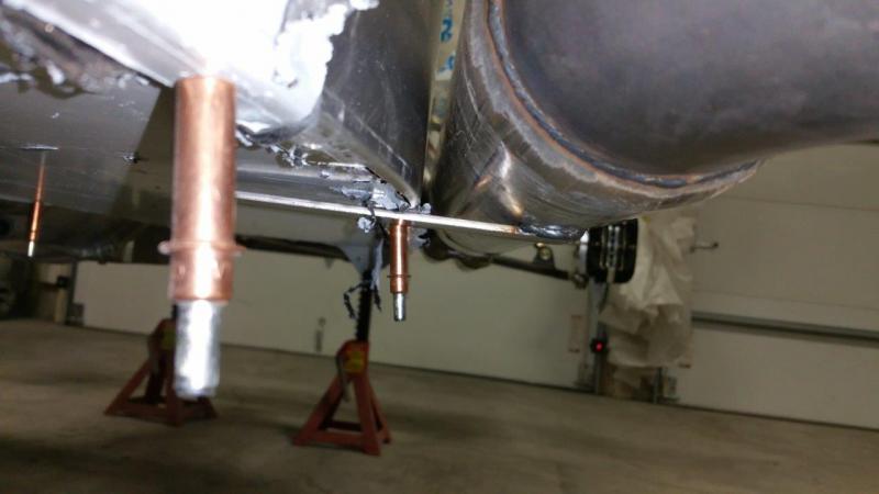
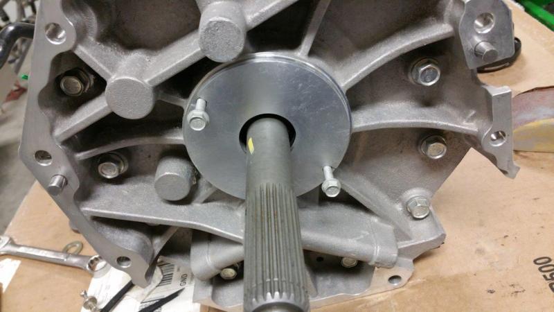
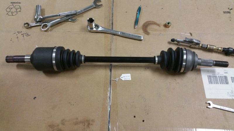
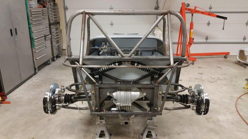
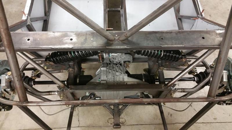
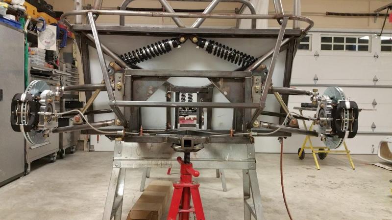
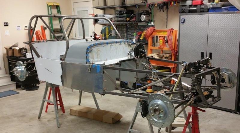
I lowered the car down to jack stands so I could start adding some weight. Differential and axles installed. Straight forward other than I had to mostly remove the spindle to get it out far enough to go on the axle. Just taking the top joint off would not let it tilt away enough. I did take the circlips off the diff side. Even well greased, the axles do take a little force to pull through the splined hub. Tightening the nut sucks them in easily. They are not going to just slide out when it comes time to remove them though. They do have a big indent in the end, so I think an air chisel with a dull point would bang them out when the time comes.
-
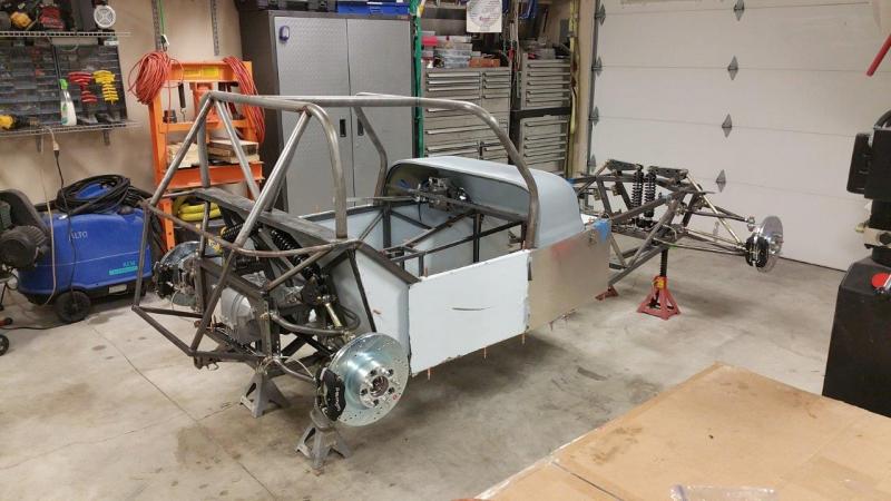
Thanks. I actually thought when I got this last summer that being done by spring was feasible. I think I was wrong I am fabricating a lot more than I thought I would need to. I underestimated the build time of such a basic car. It is always good when you get to start on something different though. I decided to stay up late last night to finish the brakes and get the garage cleaned up again to start on something fresh.
-
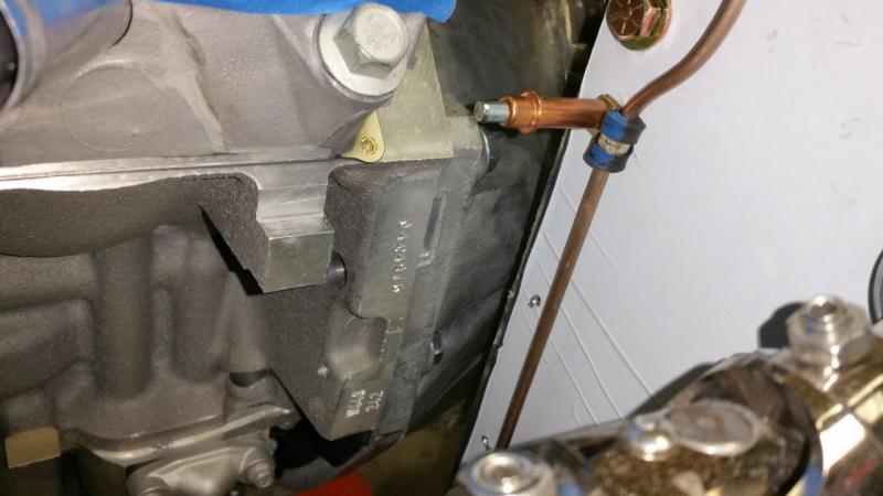
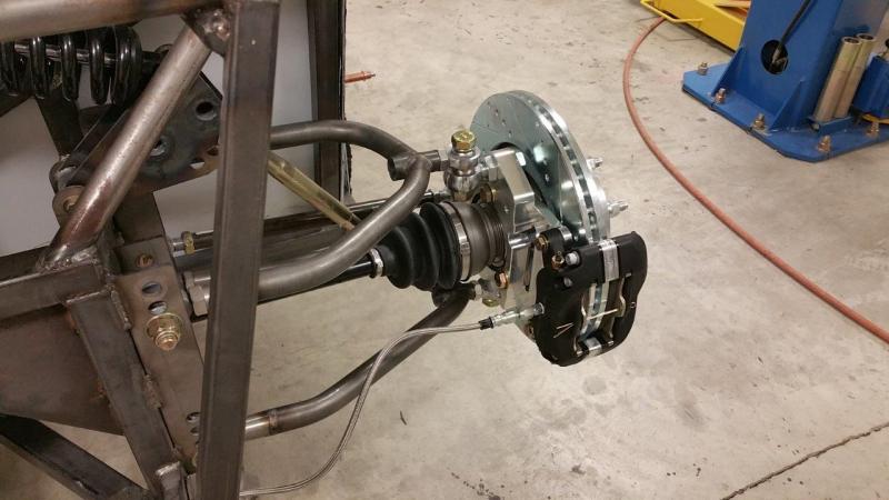
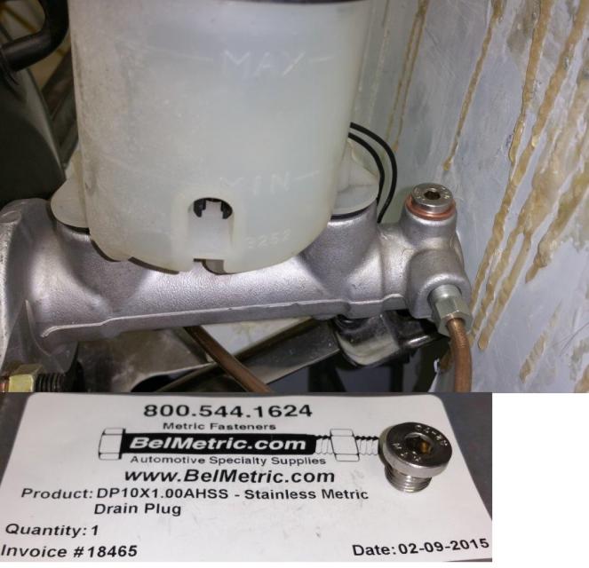
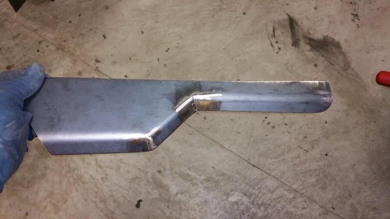
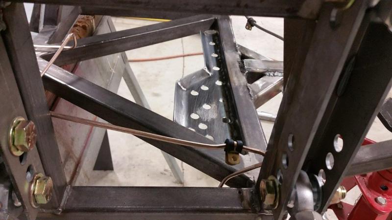
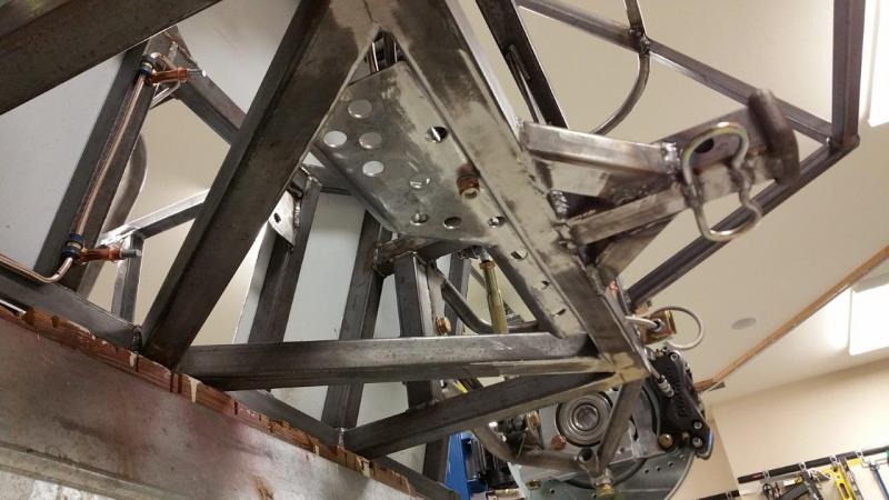
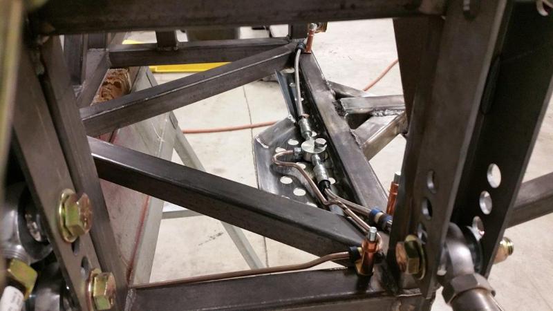
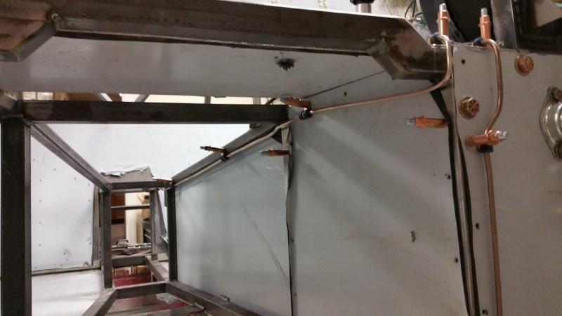
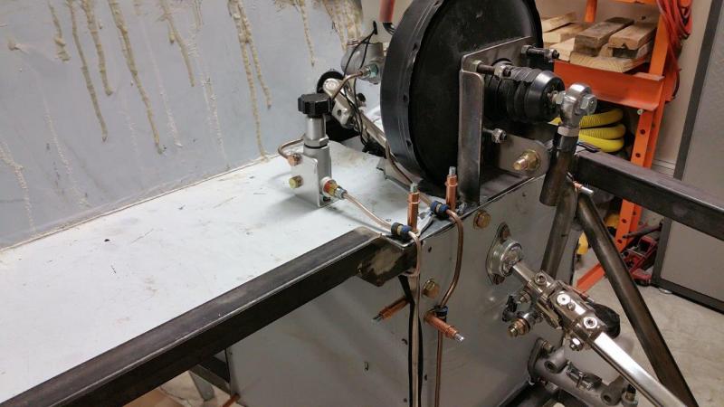
Finally finished the brakes. I still have to decide on adding parking brakes. I did rule out a brake on the diff/driveshaft. It is not feasibly for any savings of weight or simplicity for various reasons. The only beneficial way to do it is at the rear rotors. I had to order a plug for the extra master cylinder hole. I found a nice stainless steel one for under $2 from belmetric.com. Part number DP10X1.00AHSS. I did order some 10mm copper crush washers, but I found the ID was larger than I liked. I ended up using a standard size that fit tighter from my assortment. I also ordered some metric flanged nylock nuts and some different bolts for the driveshaft as well as some more brake line and other stuff from belmetric. They were reasonable and the shipping was around $7.50. They shipped quickly. I also replaced that 90º banjo fitting on the side of the master cylinder with a fitting with a coned end that accepts the standard size brake line fitting. I just happened to have one of these, so I don't have a part number handy. You will have to either use that banjo fitting, or get the coned end (AN??) fitting. This port does not have the inverted cone inside for a flared tube to work. I chose to route the rear brake line much different from Brunton. This was more work though. However, it allows you to remove the rear end without removing any brake lines and also moves them where it is not likely to damage them if you let the rear end rest or hit the frame tubes when your snaking it out. I made a 14 gauge plate and welded it in to protect the lines since they were now on front of the frame tube. This way if you spin off track or bump something on the road etc, it will not likely damage the lines. I drilled and chamfered some 1/2" holes to allow road debris and liquid to escape easier. Saves a tiny bit of weight also I suppose. I mounted the rear bias valve up front since I don't expect to adjust it while driving. This way I won't have to have that extra hole in the center console. I know some people have said that even with the bias on there, the rear brakes may be too strong, so this leaves me some area up there to make some mods or changes to reduce the rear brakes further if needed. I don't have the kit supplied throttle contraption up there, so it leaves me lots of room in that area. I think I used more adel clamps than Brunton shows, but I like to have one about every 12" and/or near bends where it could vibrate against the frame. I tend to like the lines hugging the frame just for a little more protection from accidentally banging them with something. I used 1/4" ones on the flexible lines and they fit very nicely.