jevs
-
Posts
316 -
Joined
Content Type
Profiles
Forums
Store
Articles
Gallery
Events
Library
Everything posted by jevs
-
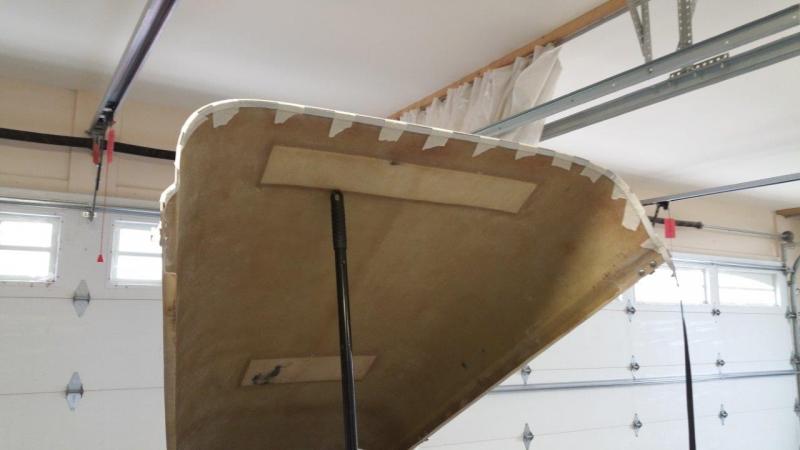
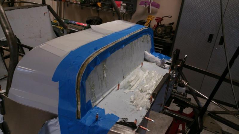
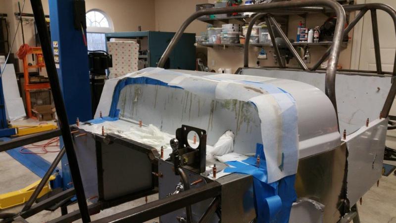
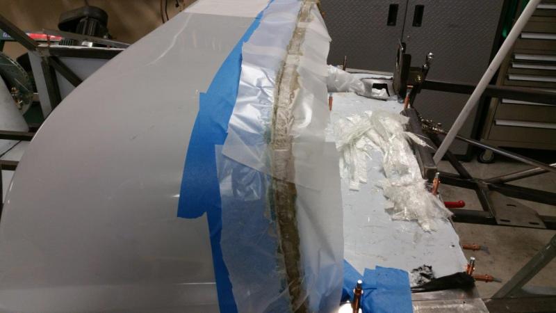
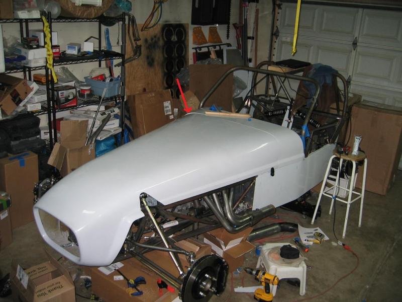
I got my rubber hood seal. It is a firm rubber, which is exactly what I wanted. So I decided I had to get back to the fiberglass torture since the pedal hurdle was defeated. I was going to just grind the lip out and build it up manually, however thanks to some bad resin that gave me more working time than I should have had, I got a better idea. I had time to think of letting the hood mold it for me. Well this worked, but it would never set up for me. I tried to blend some good resin in with the bad, but I just got a candy shell. So, I removed it all the next day and started over. This time I taped the seal to the hood. I applied all the glass and resin and then covered it with wax paper and set the hood into it. I then clamped the hood down and let it cure. This worked great. It did allow the hood to kind of go where it wanted a little on the drivers side. The passenger side was already getting a little firm, so it did not squish as much. There was no way to get it on the first try, since I actually want the scuttle to force the hood where it needs to be. Anyway. I did a lot more sculpting and got the passenger side pretty close without adding any more glass. I had to add some more on the drivers side and let it get hard so I could sand it down until the hood set where I wanted. I then had to add a little more to fill some low spots last night, and that is where I am now. It is getting there, this should work out so I can use a seal under the bottom lip on the sides also. The top corners of the scuttle are going to have to be shaved off a bit to match the hood once the lines are right. No way around it. The hood edge is just smaller than the scuttle, but I got it now so not much will need to come off for a nice alignment and the hood is held nice and tight.

-
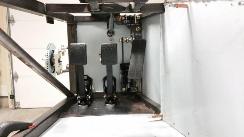
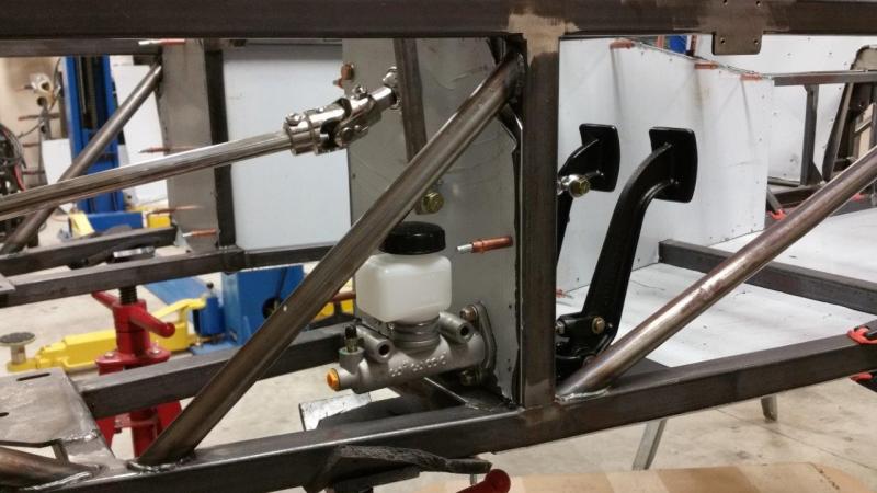
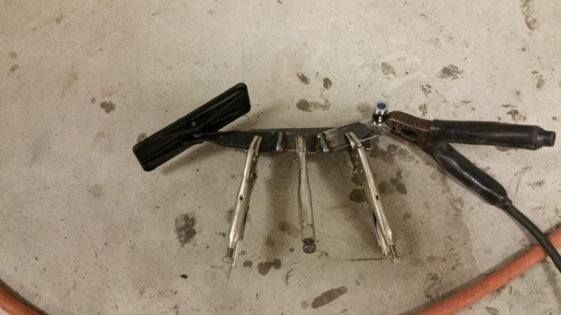
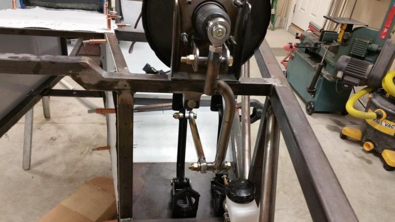
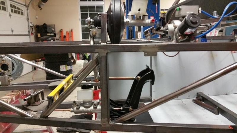
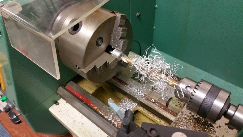
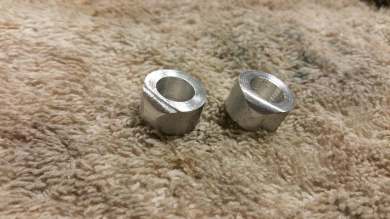
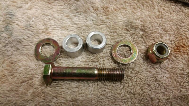
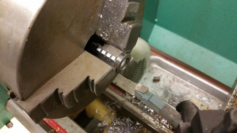
I finally finished the throttle pedal setup. I ended up with near the same pull as stock and 3-5/8" travel. I used a 5/16" male and female heim to join the two parts. I did have to make both the female and the male heim parts shorter. I machined my own spacers from spare hardware in my "spacers" bin. I also finished the front aluminum panel. The shop was a mess after all this cutting, grinding, and welding, but I got it cleaned up and ready to make a fresh start on something else!
-
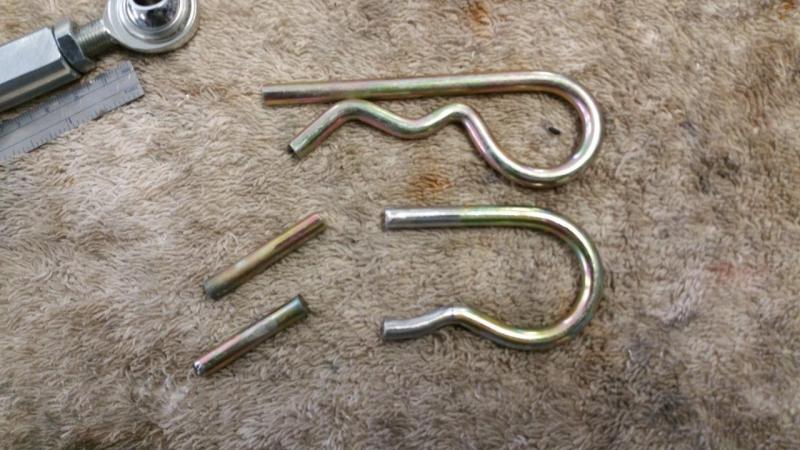
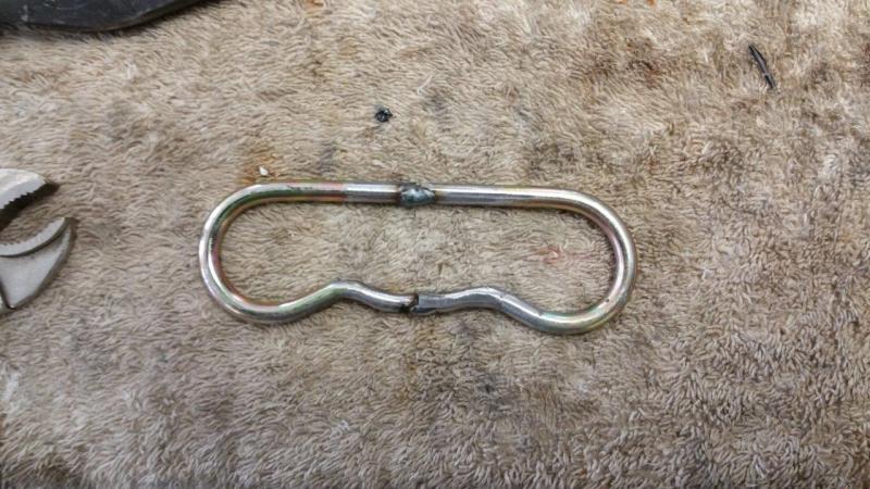
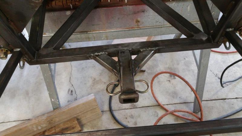
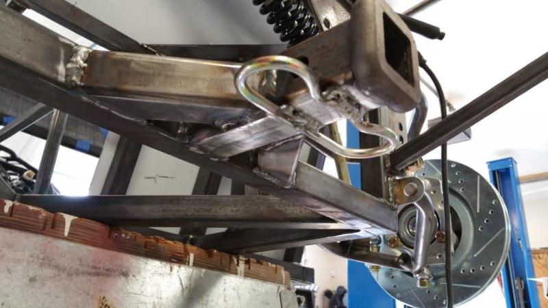
After waiting for a backordered class 1 safety chain loop for months and then being told it would be even longer, I finally gave up and made my own. This one is better anyway because the shape will make the chains want to be away from the receiver tube more so the coating will last longer. I used 1/4" clip pins. I stretch them out and matched them up to my Curtis class 1 hitch on my other car so they were the same diameter. I then cut them and tacked them together. It was easier to line them up on the car as one piece.
-
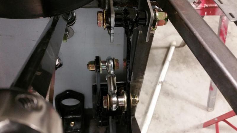
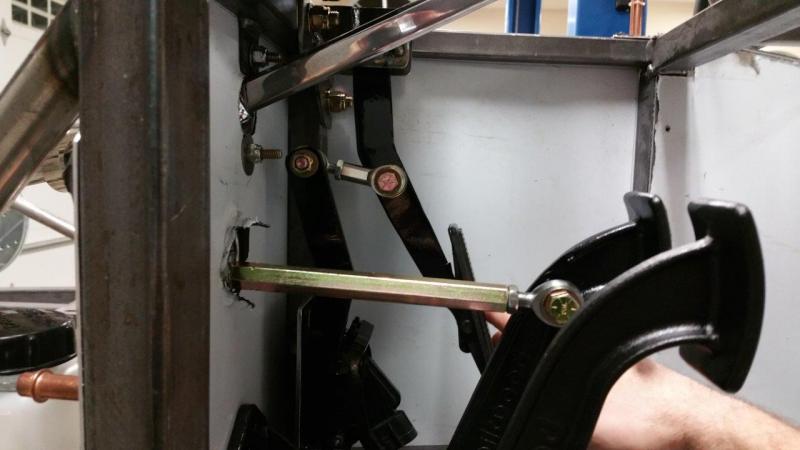
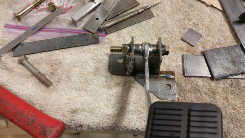
Finished the bracket for the sensor mounting. I just have to get the heim attached now and round off the sensor arm so it looks better. Based on what some of you are saying, I might bump the throw up to 3.5". It looks like the tension is going to be good. No other springs needed and close to stock feel.
-
Nope.
-
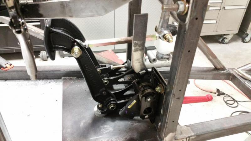
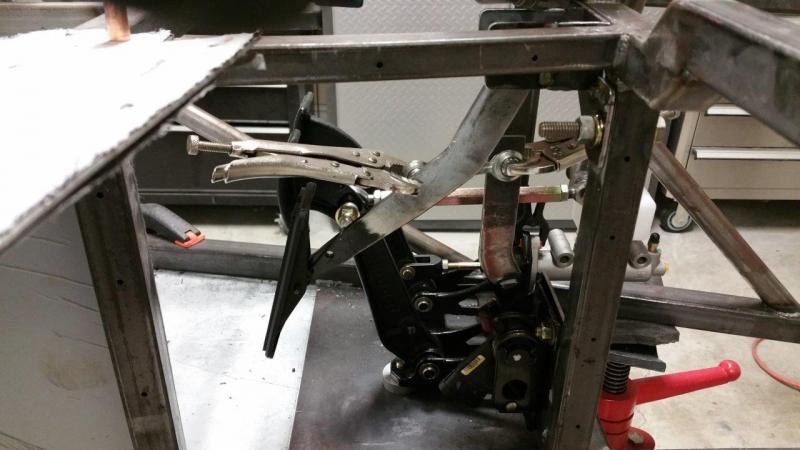
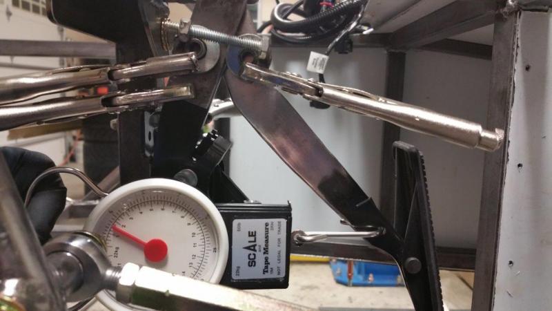
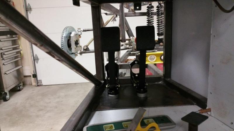
Here is the pedal bracket. It is very solid and works very smooth. I have to order some proper length fasteners. I rigged up a pseudo heim joint to experiment with travel and pressure. I am using a cheap Wal-Mart fish scale to measure the pedal effort. The stock setup was 4.5-5 lbs at full throttle with the scale hooked to the hole down by the pedal. I am going to try to stay close to 5-6 lbs and get about 3" of travel. Stock was around 2.5". Plenty of people are running high horsepower cars with stock travel and I never hear them complain. I think more than 3" might just make more work for your foot and put it in more angles. More movement is slower, but you have to find the happy balance of control and ergonomics. I welded a long piece to the sensor stub. I am not sure where the sensor is going to end up yet. I am now working on proper placement of a connecting joint and the up/down position of the sensor. Having to clamp things up and mock it up with this much pressure is tough. I probably need to go ahead and tack a plate in for the sensor so it is more solid than holding one tab with vice grips. The other challenge is that there aren't really any heims short enough. I did figure out a way I can cut a heim and make a really short one that is still adjustable. I will just have to order another one. The one I bought for the original setup has an aluminum threaded rod and I need steel so I can cut and weld on it easier.
-
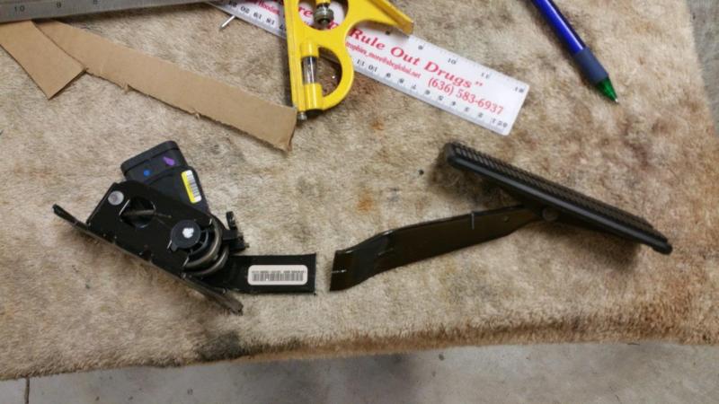
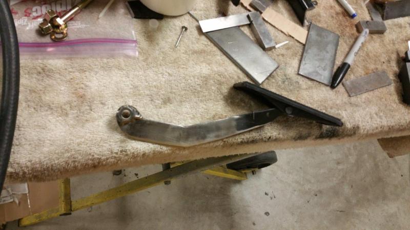
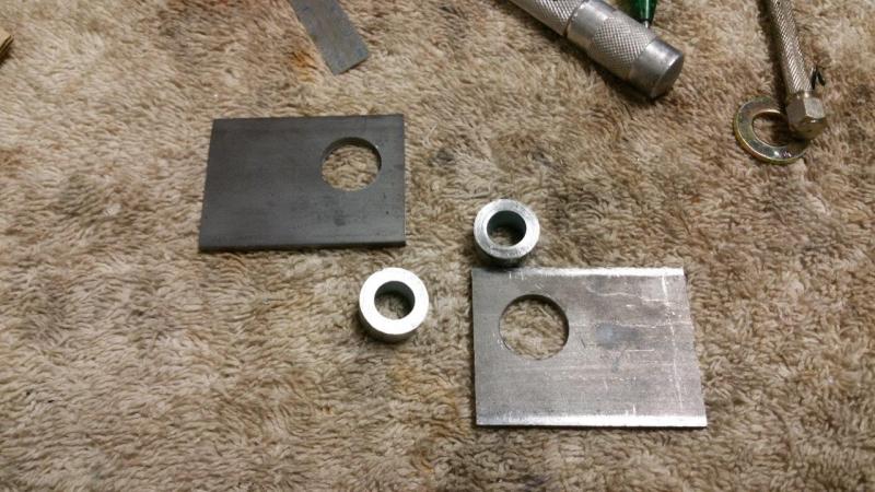
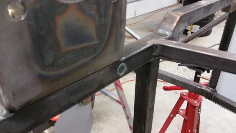
I have been working on the throttle setup for quite some time. I decided I did not want to use the supplied setup for various reasons. I wanted to retain the same arc location and movement of the stock C6 pedal. I also wanted to utilize the stock rotating pedal. I like it a lot better than that small stationary pad. I started thinking about the way I drive and the way my foot moves and the angled stock rotating pedal just makes more sense. There are also options later to replace the plastic part with a nicer aluminum part if I ever wanted. I started by doing some measuring of the stock pedal and making a paper trace of the shape. I then went ahead and cut the stock pedal. I rebuilt the pedal assembly to be shaped like the original with the same distance between the pivot point and the pivot point of the plastic pedal. I also made it straight without the jog. I added a bushing at the top pivot point. I machined some outer bushings and side plates to make a bracket. It was also necessary to weld spacers into the frame at the pedal mounting points so you can tighten things down properly and not squish the square tube.
-
How well did the check valve fit being 12mm barbs on both sides? We need a pic! I am still hung up on how I am going to do the throttle...
-
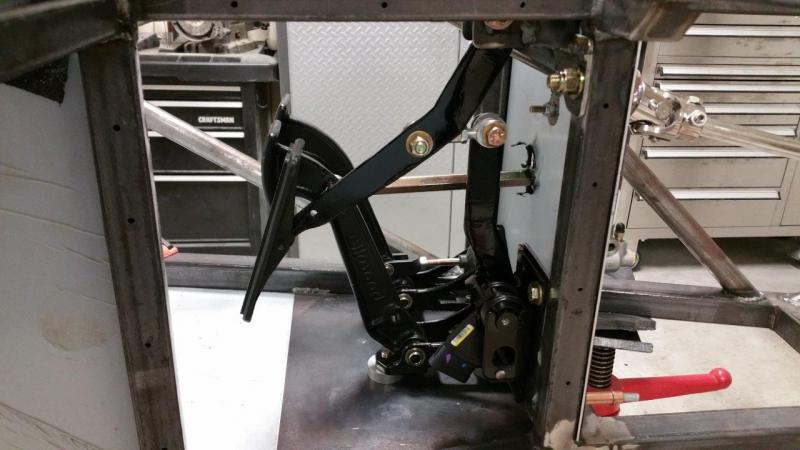
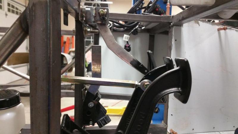
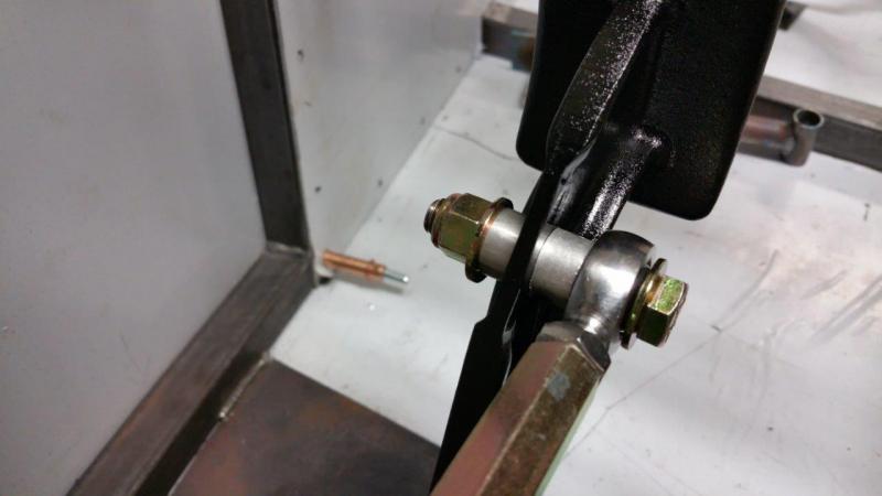
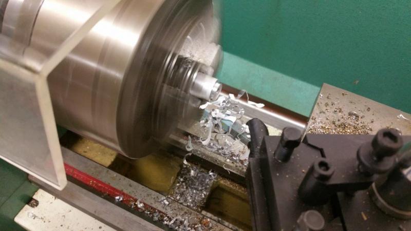
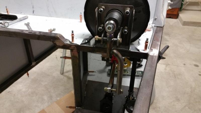
I drilled the rod out that goes up to the booster and welded the spacer through it. This way the bolts and the heim all fasten together like they should. The way it was supposed to be just puts a bolt through with a washer on each side of the round tube. This makes it so you cannot tighten everything or the tube would crush, so you would have to leave it loose. This setup is rock solid and should never give me any wear issues or come loose or get sloppy.
-
I spent all of last night working up some proper fastening of the brake assembly. I machined some spacers to fit the pedal and got it setup so that everything is nice and snug with no sloppy fitting parts. I made the spacers and the hole in the pedal so the bolt shoulder is a very light interference fit (spacers and pedal hole same ID as bolt should OD, no slop). I cut a longer bolt down so that the shoulder would be longer. I also machined some spacers to use on the rod to the booster side.
-
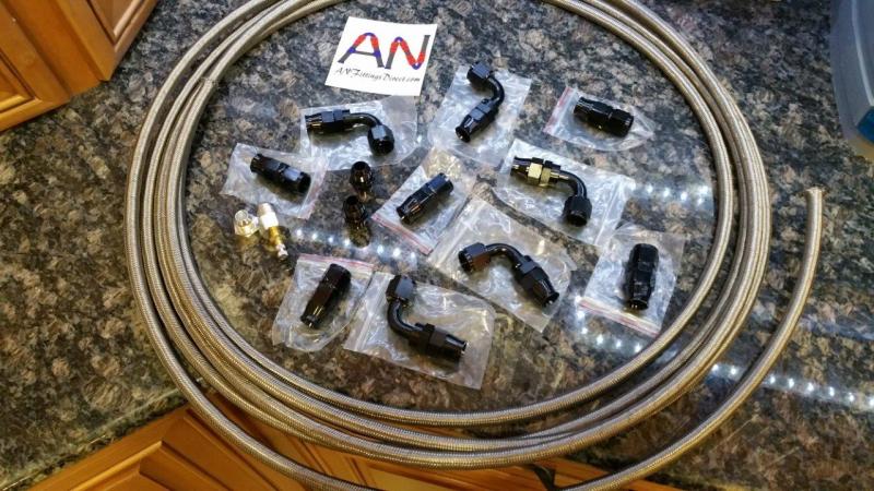
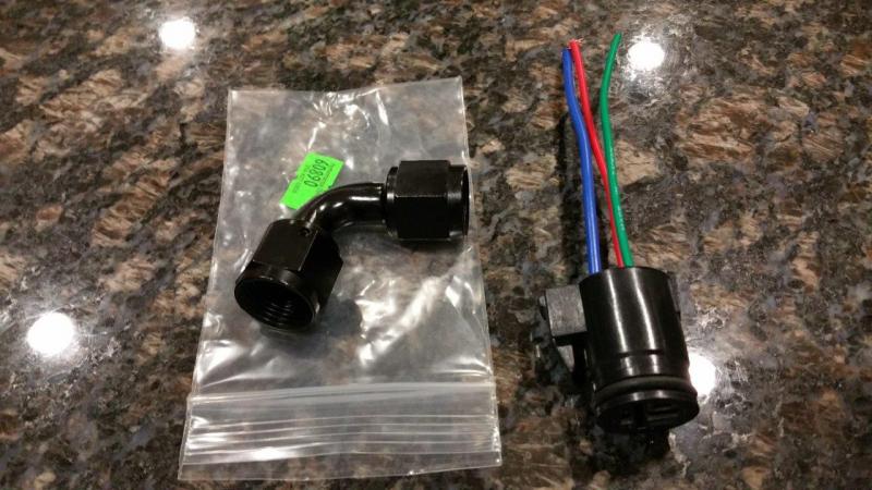
I got my PTFE fuel line and some more fittings. I also got the pressure testing kit for -8 AN. I decided to go with the Canton 12 ORB to -8 AN fittings instead of getting the Fragola ones. In talking with Canton they warned that some of the other brand fittings may hit or get too close to the filter elements and smash into it or reduce flow. I would have rather had black, but I did not want to end up having to machine them down if they were too long. I also got the same alternator plug that toedrag found. It fits great, but the only down side is that there is no sealing on the back side. It has an o-ring seal on the mating side. This will have to be sealed up to keep moisture out. I am not sure if I will just fill it with black RTV, or do something else. I also got a new 90º elbow since the first fuel pump fittings I ordered where machined poorly and messed mine up.
-
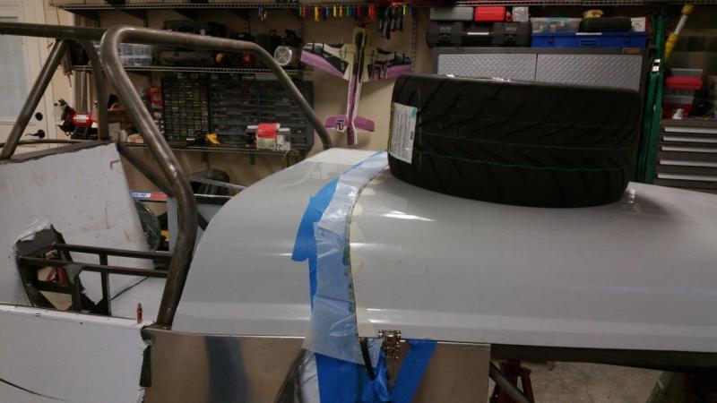
Looks like yours does the same thing as mine. Once I get the scuttle shaped to match the hood correctly, which will fix some of this, I suspect I will be shaving some off the scuttle to match. I want my hood to line up right all they way around which is going to be a bit of a challenge.
-
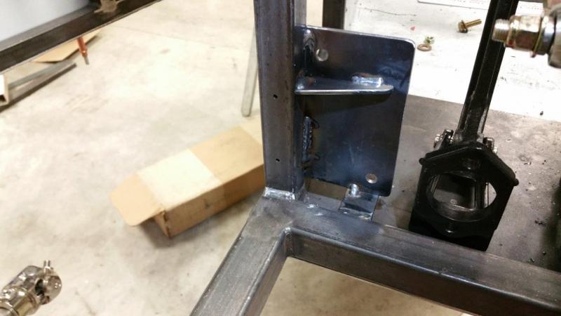
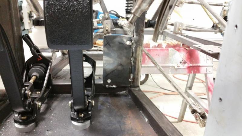
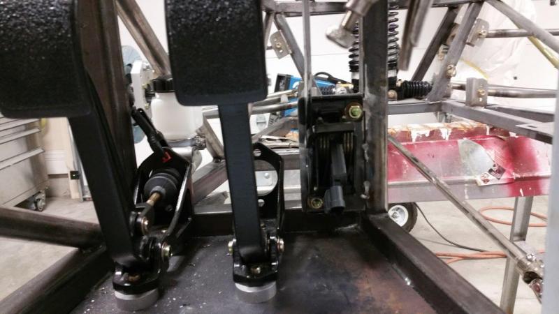
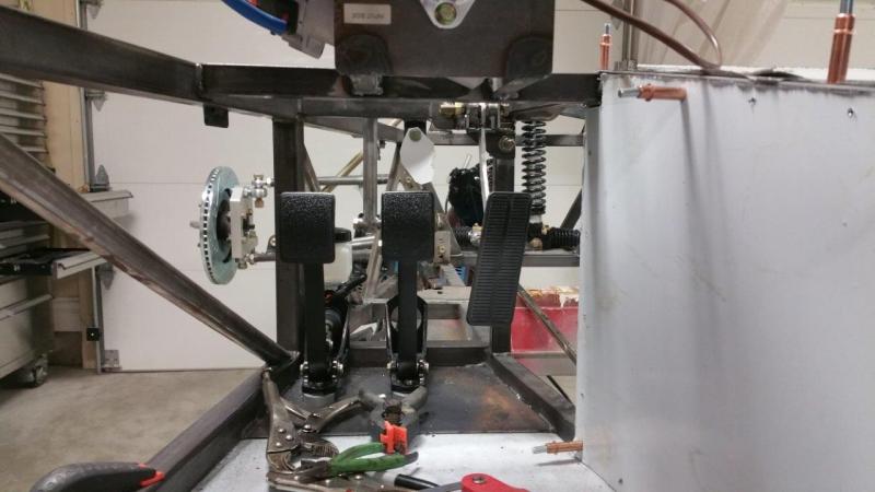
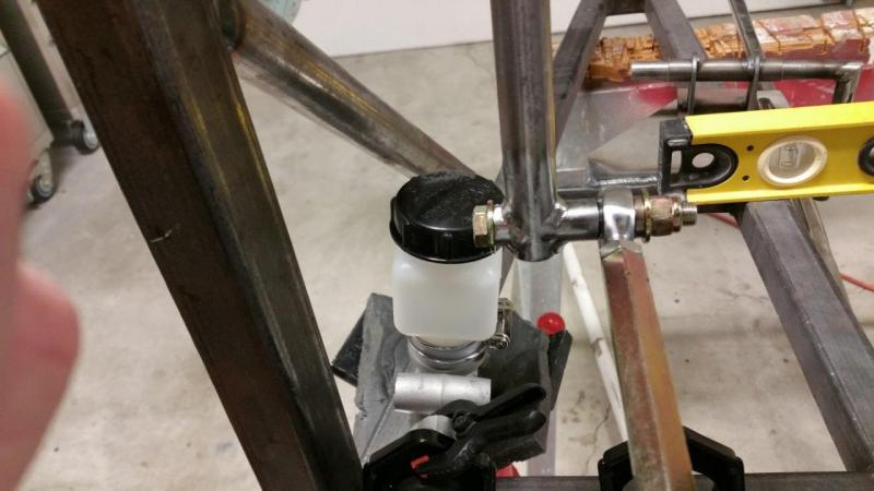
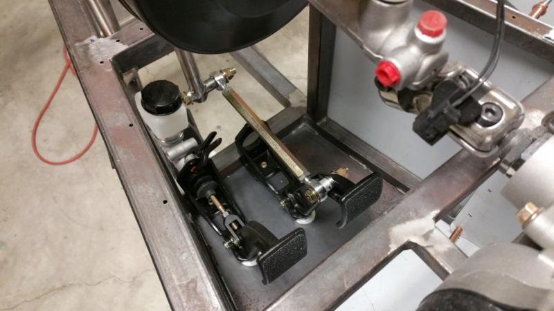
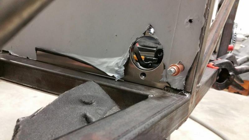
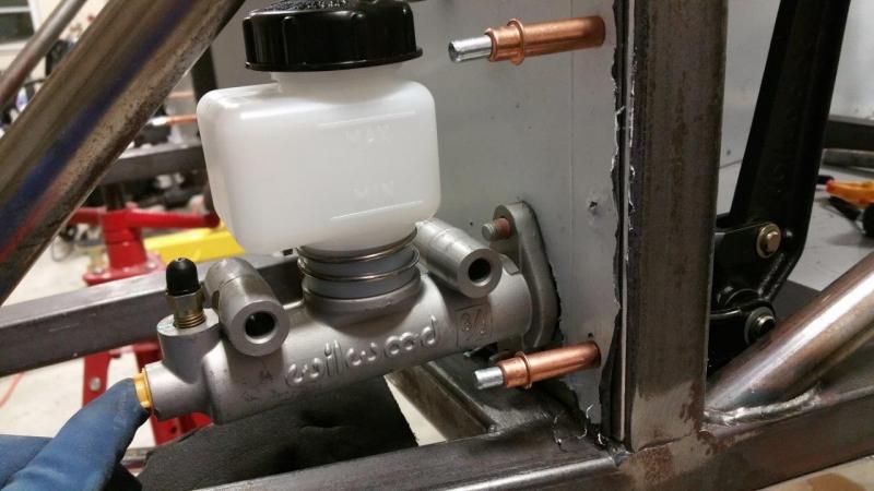
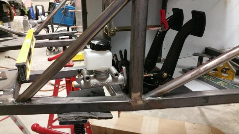
Moved past the hood for now since I am waiting on that rubber strip. As far as I can tell it still has not shipped. I got a good amount done on the pedals. I did some research on optimal spacing which consumed some of my work time. I looked up several pedal sets from Tilton, Wilwood, and a couple others. I came to the conclusion that a good averaged of what I was seeing would be about 4" or a little over for center to center spacing between the clutch and brake. On the regular size frames Brunton runs the clutch at a little bit of an angle along the outside frame rail to get more spacing. This is not required on the XL. I put the clutch all the way to the left and then backed it over just about 1/16-1/8" from touching the frame. I put it straight. I used one of my daily worn shoes to make sure I had plenty of clearance. Everything worked out nice on the clutch to put it through the aluminum panel and the reservoir had plenty of room on the master cylinder. This area will be sealed up nice. There will be a hole for the brake rod that I have not made yet. I got the brake linkage all done except I have to make a spacer where the heim bolts to the rod that goes up. I also have to drill the hole in the brake pedal. I quit for the night at that point. I need to finish up those couple things with the brake and then I will do the throttle.
-
http://www.homaxproducts.com/Browse-Homax-Products/Welder-Adhesive-Professional-2-1-oz-Tubes Stuff seems to stick to anything. I use it to glue my foamy 3d planes back together. I have used it to glue kids nerf toys back together and toy cars etc. It is kinda like a contact glue. You put it on both pieces let it set for about a minute or two then stick them together. I have also used it just to glob things together (not relying on contact procedure). You could get this stuff at Lowes. I haven't bought any for awhile and usually buy stuff online so I don't waste my time. Oh, I used in the middle of winter to glue polycarbonate lenses back into exterior LED lighting in my soffit also. So, it holds up to heat and cold well. We get 0-100 degrees around here (Missouri). It is snowing today (white outside). Time to buy a plow for the lawn mower.
-
Maybe lay it out on a sheet of plywood, 2x4, 2x6, or whatever you have laying around. Pull it with just a tiny bit of tension and fasten it down on both ends. Then make two slits with an X-Acto knife and a straight edge. Then when you have the two perfectly spaced slits, cut the ends out. This is what I would try. But then you still need an adhesive that will hold it. Welders glue seems to hold about anything, but I doubt it would come off easy.
-
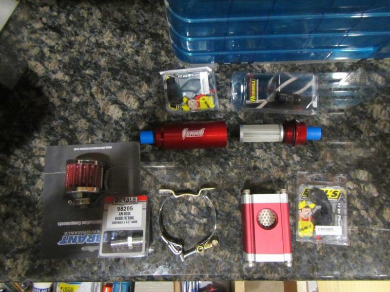
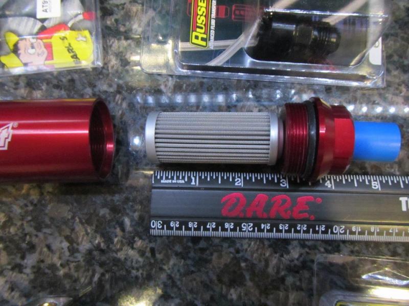
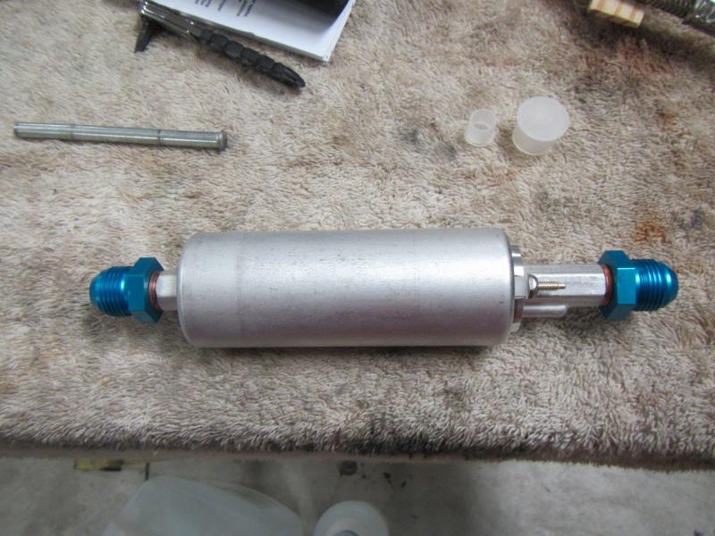
Got some fuel parts from summit. The pre filter is very nice quality. It has a 100 micron stainless filter with a lot of area. The -8 fittings for my fuel pump that I got from http://www.gsl392.com were junk and ruined a $16 Earls fitting. I found some black ones and ordered them instead. I did not want blue anyway.
-
You need to buy a welder your limiting yourself. It is one of my most used tools. MIG welding is not hard. TIG welding aluminum is. Get a Miller that can run on 220 or 110.
-
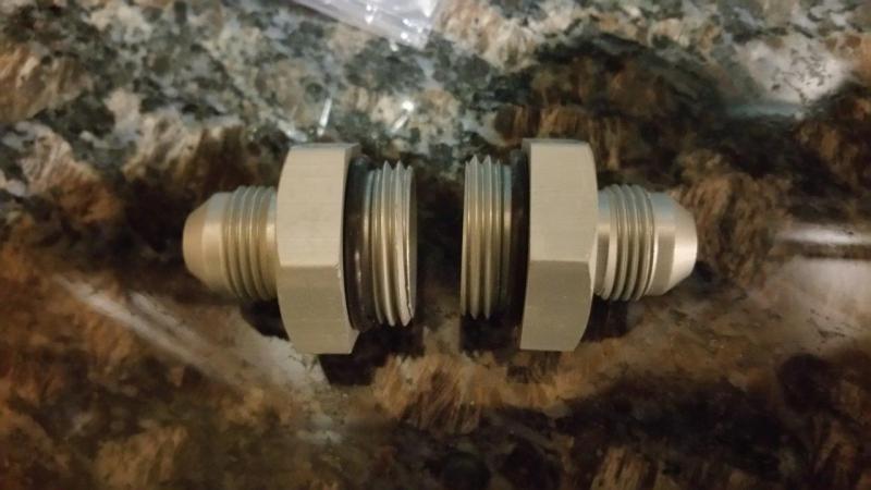
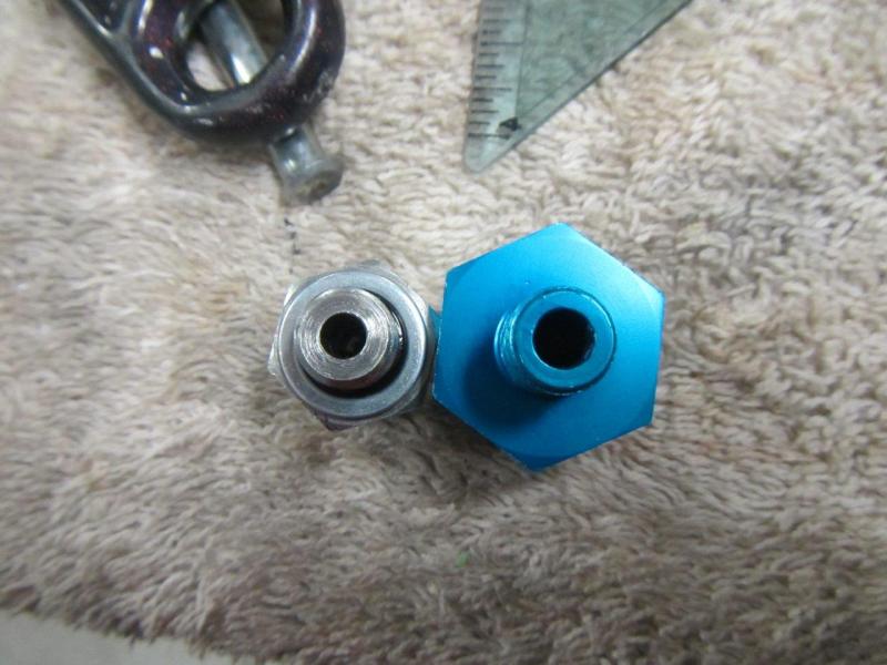
I got the new fuel pump fittings today. The original fuel system design goes up and down from -6 to -8 throughout the system. I am reducing it to less fittings and just making it -8 for the whole system. It wasn't any more expensive than -6 stuff really and the less fittings the cleaner it will look. The most restriction in the system will be the fuel pump itself. I doubt I will ever need an upgrade, but if I did, just a fuel pump swap would do the trick. However my main point is to let anyone know that might have got the -6 fittings from Brunton for the fuel pump, that you should consider drilling those out. You can see how much more restrictive they are than the new fittings I got. Also, the Brunton ones are steel so they don't need near that much meat anyway unless you plan to run a 5000psi fuel system Might as well let it flow some more for free.
-
Good info. I did not catch that you were using the elbow for the reducing purpose at first DOH!. Trying to work at the job and get car parts sorted at the same time, so I skim through things fast sometimes.
-
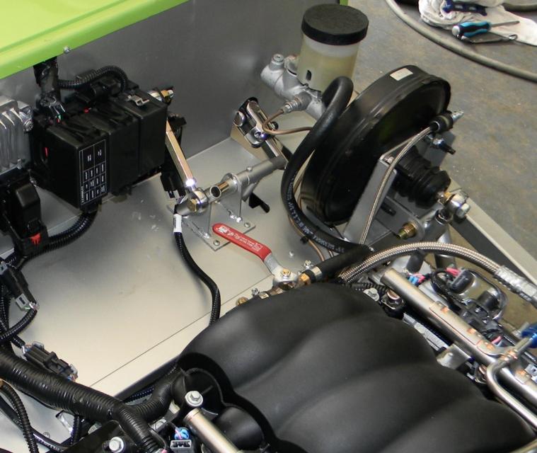
Do you think 12mm ID silicone vacuum hose would fit over the engine and booster fitting (50 miles away from my car right now at work )? I found a 90 degree silicone elbow for $3 and the line is less than $10 shipped for 10 feet. I could put the 12mm barbed check valve between those and it would look pretty clean and last forever. Oh, Brunton responded about the ball valve, and yes that was just so that customer could adjust the level of assist. They don't use it on their car. They did not say about using a check valve, so I asked again. On the car with the ball valve, I don't think the ball valve would work very good with a check valve though. When your not using the brakes, the vacuum would still build in the booster and hold until used even if the valve is only set to a small opening. It would just take longer to build the max pressure.
-
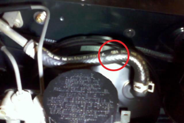
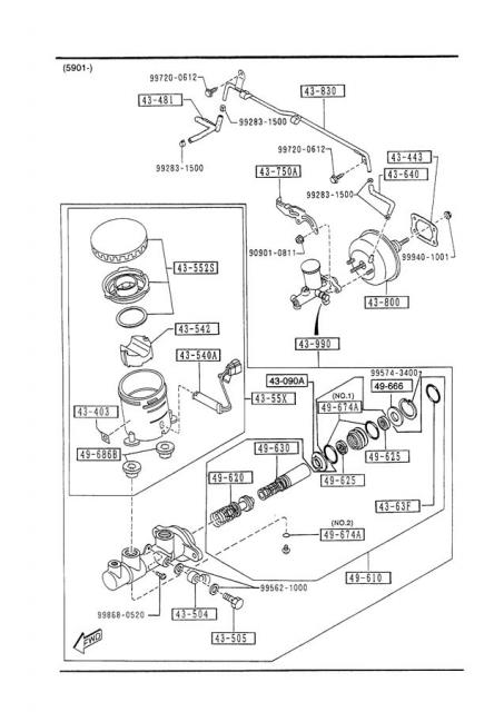
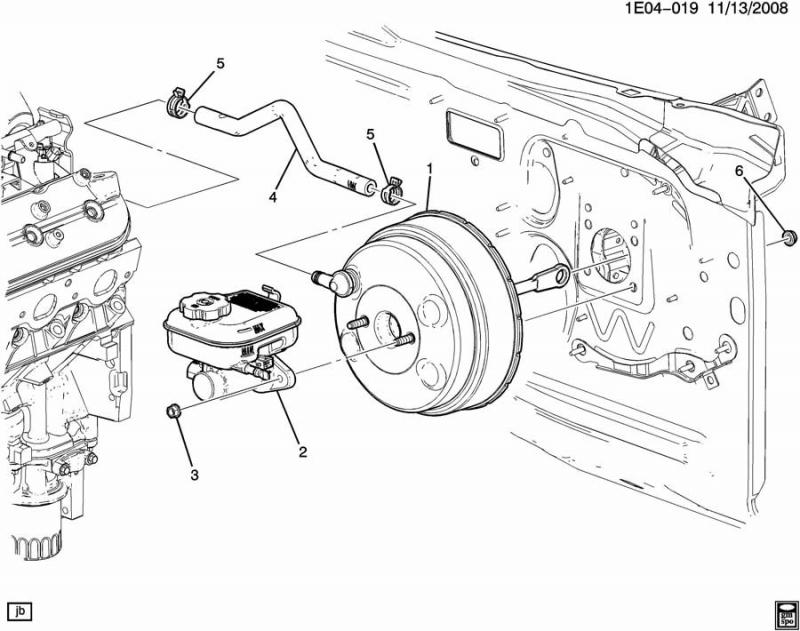
Hmm, after some reading it seems that people are saying the Miata hose has a check valve integrated into it. That must be why it is not shown as a separate part. One guy replaced the hoses with some fancy open ones and then the pedal was pressurizing and pushing his foot back or something. Found this picture where someone is indicating the location of the check valve in the hose. So, I think we do need one. I still wonder what Brunton does. Buying the Miata hose might solve the problem of the check valve and the 90º elbow though. It might cost more than buying the parts though. Do you remember what year Miata our boosters are from? I am not near mine to look at it. What size and type of hose are you using for the booster? I need to order some.
-
They shipped a couple hours after I ordered, which is a good thing, but too late to add stuff Are you sure we need a check valve? I don't see one on the factory diagram. I looked up a 96'. I could not remember exactly what year the Miata booster is. I don't see one on the lines diagram. I wonder if it already has it built in, or what....? I don't see one on the Brunton setup, just that ball valve. http://www.jimellismazdaparts.com/showAssembly.aspx?ukey_assembly=305251&ukey_make=995&ukey_model=14360&modelYear=1996&ukey_category=20230 I don't see anything on the white car. Just a hose. Looks like a 2010 Camaro SS has it built on the booster. I was wondering if it might have a check valve on our motor fitting, but judging by this, no.
-
If we need that, I wish I would have known. I saw those on the site I just ordered fuel lines from yesterday for only $4.99. Too late now, I would have to pay shipping again which makes it a little more than eBay. They shipped fast. http://www.anfittingsdirect.com/an-adaptors-for-stainless-steel-line/aluminum-one-way-check-valve-12mm-barbed--p-9583.html?osCsid=b7ba4be32f1f5b826c0b650035dd4d78 I was thinking that elbow you used was an actual PCV valve. I guess it is just a 90º hose?
-
Did you happen to notice that Brunton seems to have a shut off valve on this hose? I wondered what for, but I have not had time to ask yet.
-
I will be staying away from gas struts. Nothing but trouble. Been there, done that on a couple other cars. I will come up with a rigid light setup... Potential problems with gas charged ones: Pressure when closed can move the fiberglass or make bulges, cause cracks, etc. Gas eventually leaks and then they don't hold or provide much lift help. More expensive than a metal rod of some sort Harder to close and again flexes the fiberglass when you do. Have to get the PSI and mechanics just right or they will be too strong or too week to hold it open. Unless you get the type that have a pull release lock built into them (More expensive), then you cannot lock it open and a strong wind can do nasty things. Most of them ball mount, although this could be changed. Could be heavier setup. Anyway, there are probably some other down sides, but that's the quick ones I can think of. I like a nice prop rod for reliability and simplicity.