jevs
-
Posts
316 -
Joined
Content Type
Profiles
Forums
Store
Articles
Gallery
Events
Library
Everything posted by jevs
-
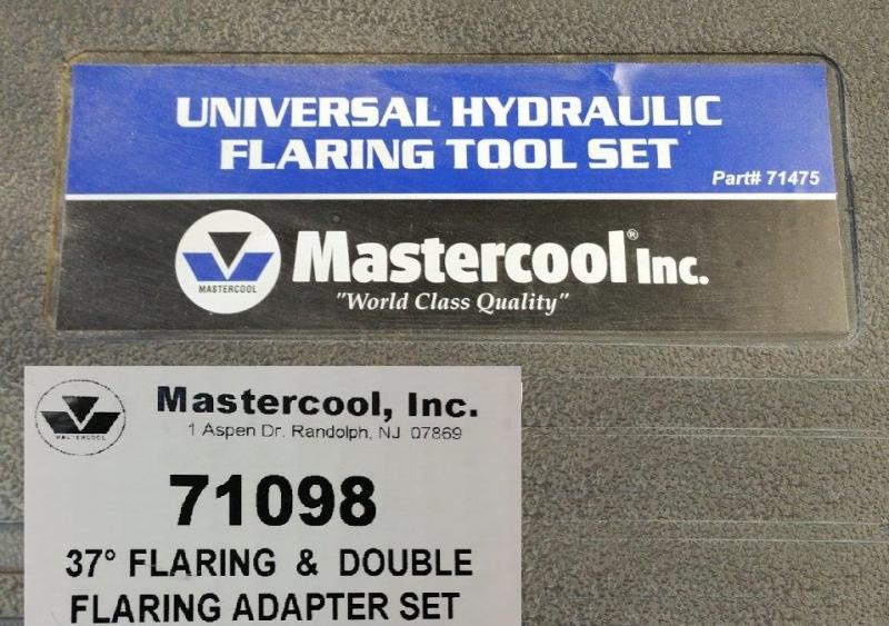
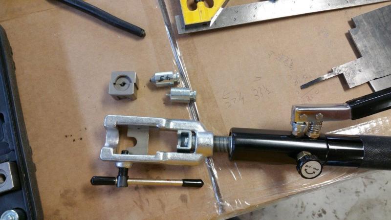
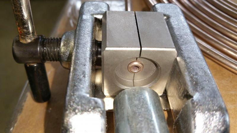
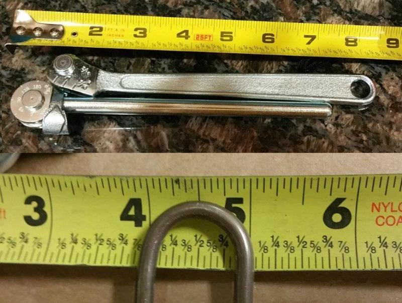
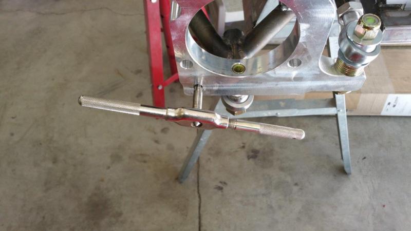
Just thought I would throw out a couple tool recommendations. This is an awesome flaring tool. It does about everything to a tube end. Very easy to use. Mastercool 71475 Universal Hydraulic flaring tool. Add the 71098 37º Flaring and Double Flaring adapter set so you can do all your AN tubes as well. That is about the ultimate combo I have found. It is a bit spendy, but you should never need another flaring tool for any future projects. If your only building/repairing one car ever, then maybe not, but if this is your hobby or job, I highly recommend it. For a double flare you just load your tube into the die with the end flush to the end of the die. Then you press the male nipple tool in and it makes that bubble looking end. Then you just put the 45º cone in and press that down and your done. This will also do fuel line quick disconnect ends and metric lines, etc. I have some tubing benders that work well, but they only truly went down to 1/4" size and your supposed to use the 1/4" for 3/16" tubing. I decided I wanted a true dedicated 3/16" bender and did a bunch of searching. In my opinion (and others), this is the best 3/16" tubing bender for tight radius bends. You won't find one that bends smoother or smaller. Imperial 364-FH-03 MADE IN USA! You can find it for under $40 on the net. I bought it at opentip.com

-
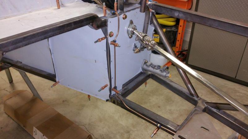
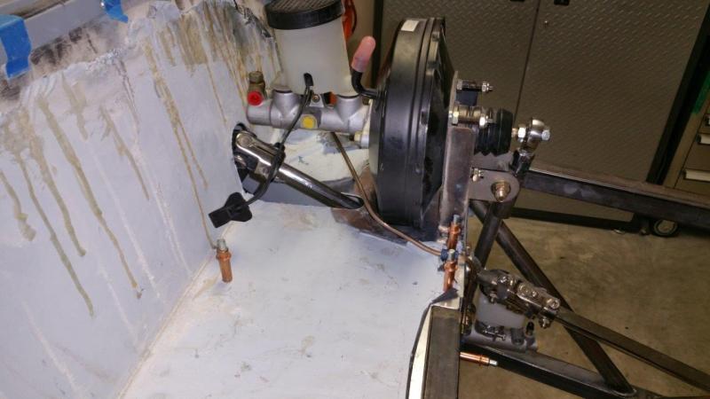
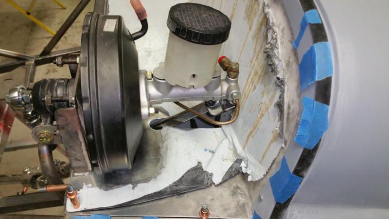
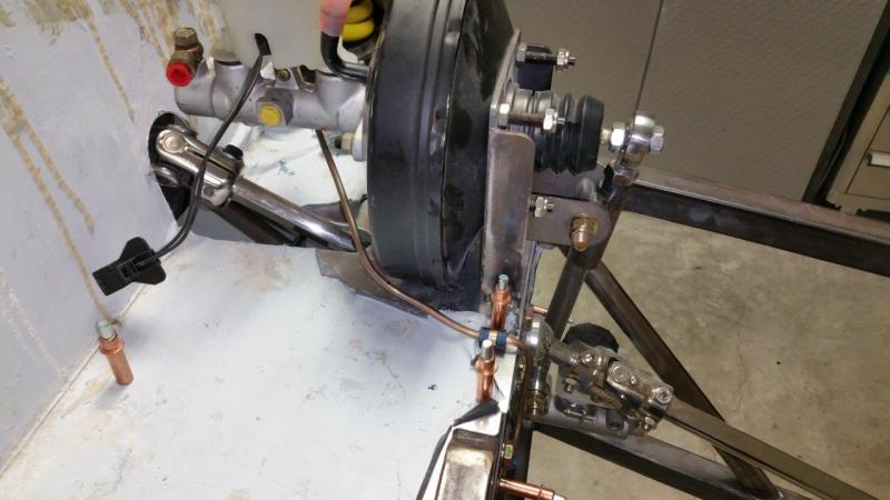
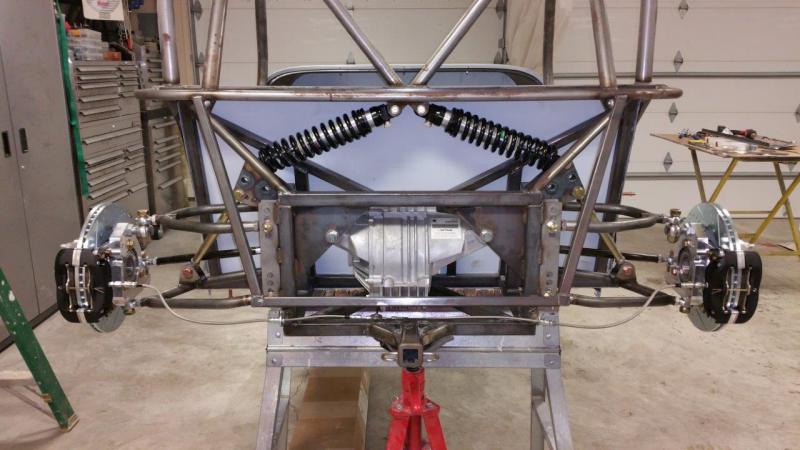
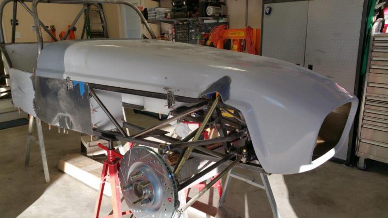
Front brake system is done. I did have to buy some different bolts for the front and rear caliper stuff. I did not get the optimal lengths or enough for some of them. There was one adel clamp added where the braided line goes under the steering. Those holders that go into the tabs on the frame still let the hose slide through them. I did not want to risk that it could slide out and somehow contact the steering joint hardware. You can see the cleco there in the picture, but the steering shaft is blocking the line clamp. I also had to buy longer bolts for the tie rod to steering rack. The threads were not quite engaging the nylon in the nylock nuts. I am going to have a lot of left over nuts and bolts for the next project The goal up by the brake booster is to keep the lines clear of the steering enough that I can make and fit a cover there still at some point. I am not sure if I want to put the proportioning valve in the center console. I wasted a bunch of time today thinking about stuff. Without sitting in one or driving it, I don't know if it will hit my arm.
-
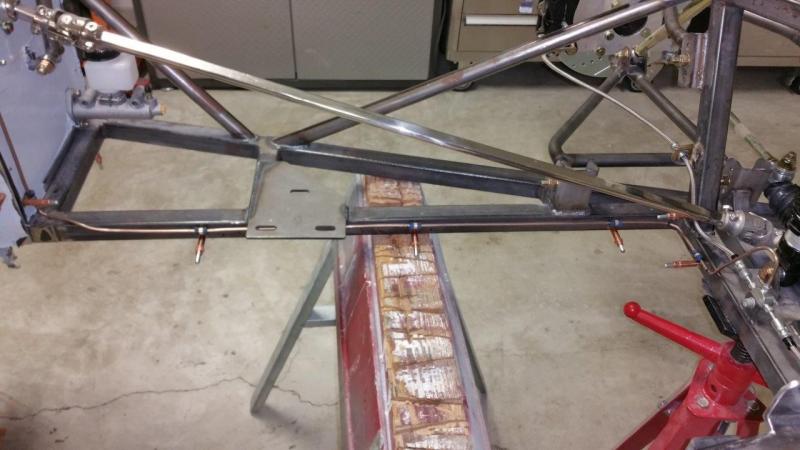
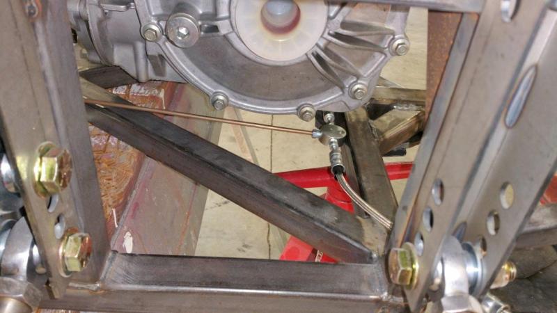
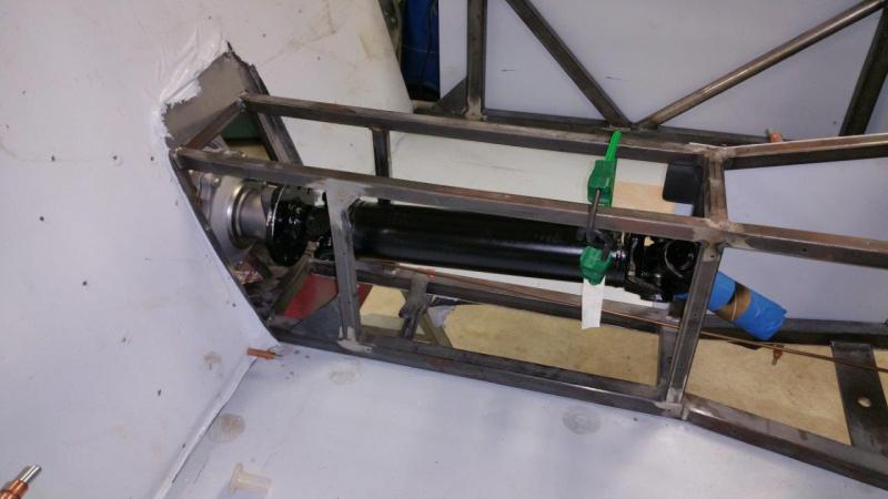
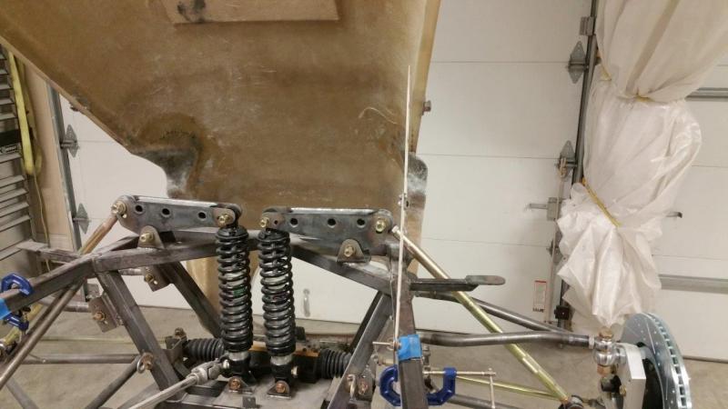
Finally back to doing stuff that looks like progress. Started installing the brakes. The machinist forgot to tap the holes for my caliper bracket on one of the rear spindles. The drilled hole was the right size to tap, so no big deal to fix. I got everything installed in the rear except I need to finish the lines. Every one that I have seen runs the hard line up and over the differential. I think I am going to stay under it. The other way you cannot remove the diff without disconnecting brake lines. I am just trying to decide if I should add a plate to protect the line in case rocks pop up or a spin off the track etc. I might never track it, but might as well prepare for it. The round T fitting will bolt to this same piece. I am not sure if I will use angle or just a 1" or 1-1/8" wide 1/8" thick piece. This will further beef up the piece that has the hitch on it as well (not that it is needed). I have the same issue as toedrag with the drive shaft bolts. The head hits on two of the three. I will probably just cut some length off. However, I may get some a bit longer so the non threaded part is longer so more goes into the diff flange, then cut those down. I have to see what is available. There was some thought on a differential parking brake also. This could be tricky because there is not much room. I am still thinking about this one. I think they work better and save weight if you can make one fit....if not, I will skip it or do something like toedrag did. I can pass inspection without it from what I have read. I just like to have one.
-
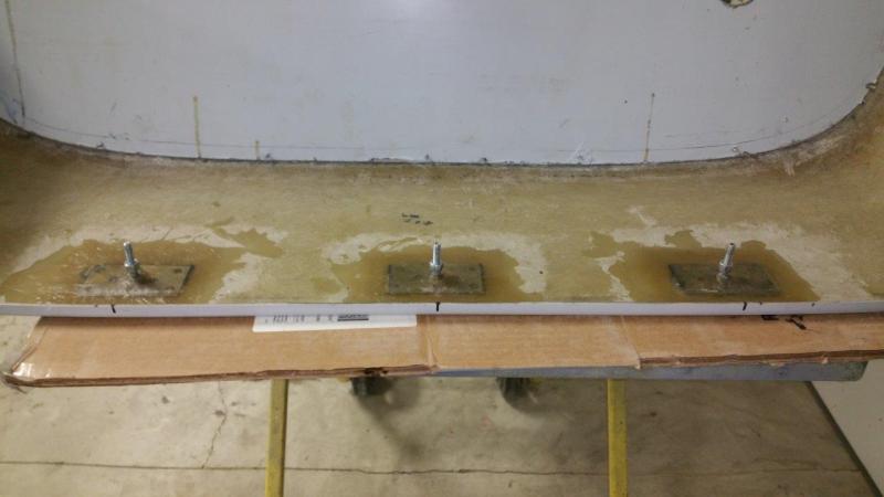
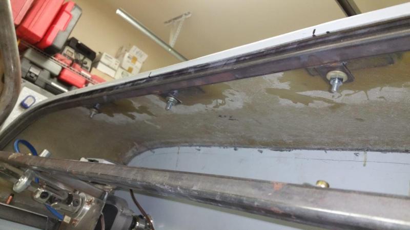
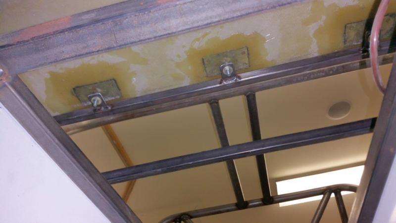
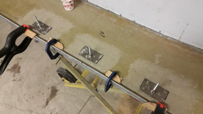
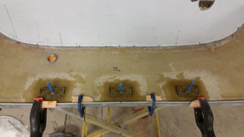
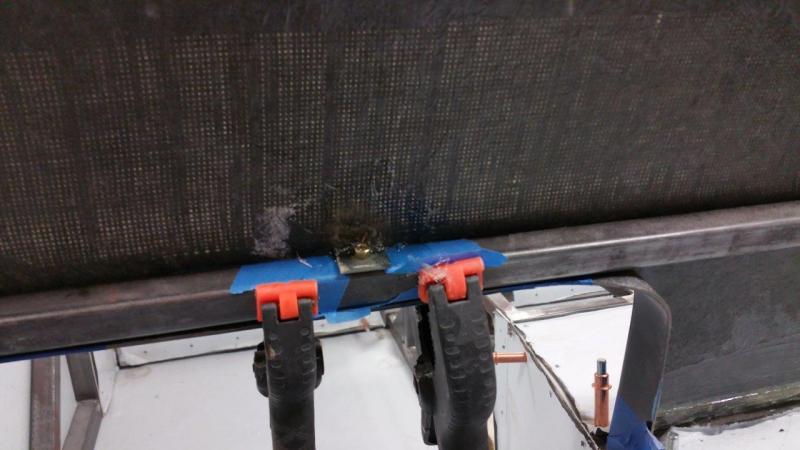
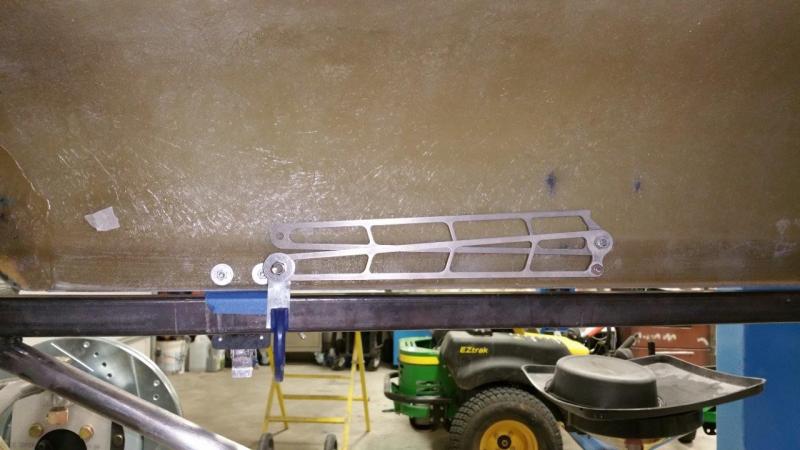
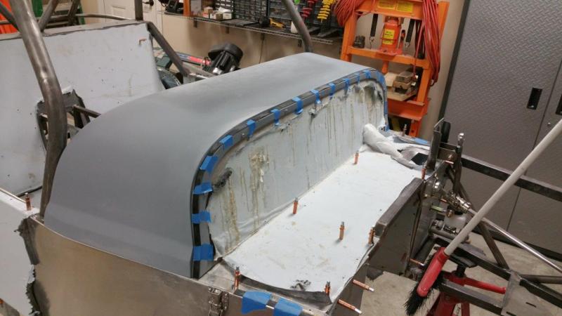
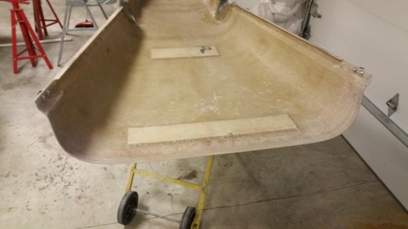
Finished the modifications for mounting the scuttle panel. I made the tabs 1-1/2" x 1". I started with a tight fit 1/4" hole so they would be placed as accurately as possible. I then put a nylock nut on each stud upside down. This way once they are adjusted, the scuttle will go on the same way every time since they won't spin or move. I made the tabs and then mounted them on the studs and tack welded them. Then I pulled everything off and welded them permanent. The studs were trimmed to leave a little room for adjustment and to fit nylock nuts on the bottom at final assembly. Once everything was done, I went one size up and drilled the holes out again. This lets the scuttle slide on very easily, even with the aluminum firewall panel still attached to it. It is very solid now. Feels like it should with no visible fasteners for the dash or scuttle when the hood is closed. I can fine tune the height a little bit across it by adjusting the upper nylock nuts
-
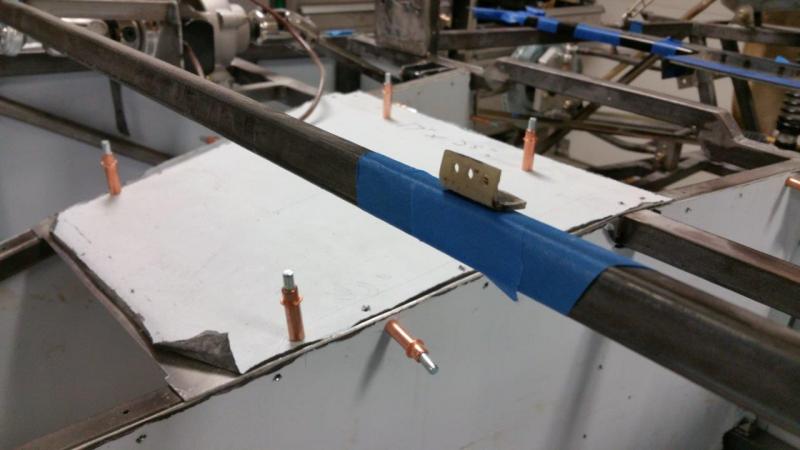
A couple more pictures of the dash panel mounting tabs. I did a little sanding to clean them up a little bit so the washers would sit nicely and also clean up what ran between the tube and the panel. I taped this area so it was easy to remove. You can just grind until the tape is gone around the edges then the rest that is stuck to the tape just peels off. I also made some plates with 1/4-20 studs. I fiberglassed these to the bottom of the scuttle. These will be used for mounting the scuttle on the dash side. It was too floppy to be left floating. The way I will finish these will also allow me to fine tune the height across the top. As it is, it is not very straight If you let it go where it wants.
-
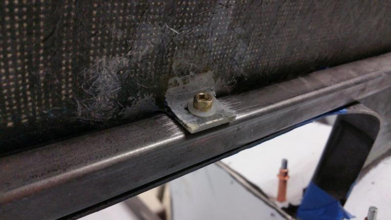
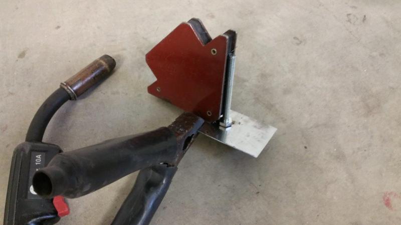
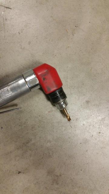
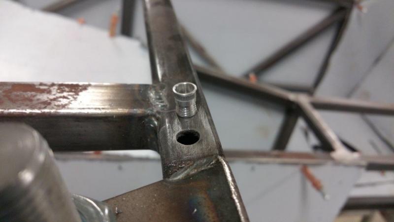
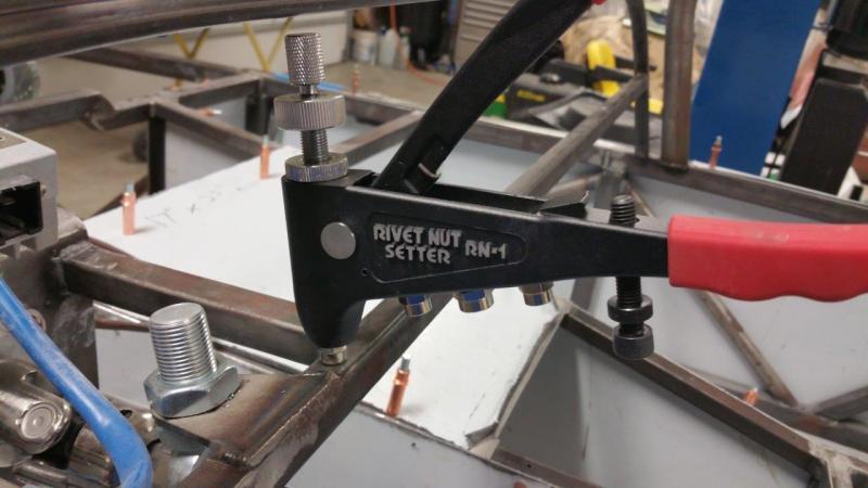
Made some hidden mounting tabs for the dash panel. This way it will be secure and nothing is visible from the front. You have to remove the scuttle to take the dash out no matter what, so it did not make sense having bolts through the front. I also don't like the method in the instructions of using double face tape to hold it. That does not sound like fun to remove and you also have to account for the amount it would space the dash panel out early on. I used some 10-32 aluminum rivet nuts in the lower frame tube. I had to make a short drill bit to use with my angle drill. There is not much room between the upper and lower frame tubes and the holes need to be drilled straight. I recommend the Drill Doctor 750X. It works good for sharpening bits, and reshaping if you need to cut a bit to make a short one. I made the tabs out of some scraps I trimmed off the dash panel earlier.
-
Is your turn signal toggle momentary? Also, if you have not purchased it already, I recommend getting the one with the brake input. This way it stays flashing as long as you hold the brake and even If you let off and then reapply the brakes before the timer times out, it is supposed to hold it on again until you let off and then restart the countdown. Should be much more convenient than hitting the button every time the timer goes off if your in a long traffic line, or a long light. Wiring diagram attached. I got the 1007 Signal Dynamics Penta-Star Turn Signal Control Module 01007 Penta Star.pdf
-
Performed a few heat/cool sessions with the heat gun on the hinge area of the front and now the hood opens straight up and down.
-
I chose to actually push the backs of the brackets up when closed instead of level with the frame rail like I was thinking before. This makes it even less likely that they would get in the way of anything. No loss of opening distance either. One thing that I knew existed before is very evident now. The lower front of the fiberglass where the hinges mount is not really symmetrical. This causes the hood to pull to one side when open. When it is closed, it just kind of flexes a little and the hinges can move independent, so it is no big deal. However it bugs me when open because it wants to lean to one side. I will be using the heat gun to try and rectify this. These super light aluminum hinges are tough, but the sides can flex very easy. They are rock solid up and down. They will let the hood sway when open, but they will not let it close no matter what you do. I did make all my mounts beefy because I can always make new steel props to take out side to side movement if I want later. However, I think it is fine as is and looks better and saves weight. It is hard to tell from the pictures, but I left plenty of gap between the props and the hood when closed. This way nothing can ever vibrate against anything and make annoying noises By the way, that blue tape you see is just holding my rubber strips temporarily so everything is where it needs to be so things fit right on final assembly. The only contact points with the rubber will be at the aluminum pieces. The hood rides above the steel rails everywhere else. This will save the paint/powder coat from rubbing off and gives a nice even gap. I also did this so that there would be a proper space if I should ever want to add side panels in the front. They will fit right in between the hood and rail with no mods and allow the use of the rubber seal along the whole length. This is why I also put the aluminum piece under the front hood latches. If I ever make side panels, the clamps would still be right where they are now. The side panel would just replace the piece of aluminum in there.
-
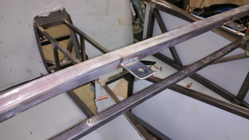
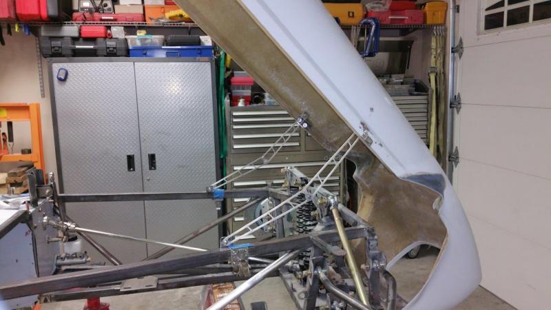
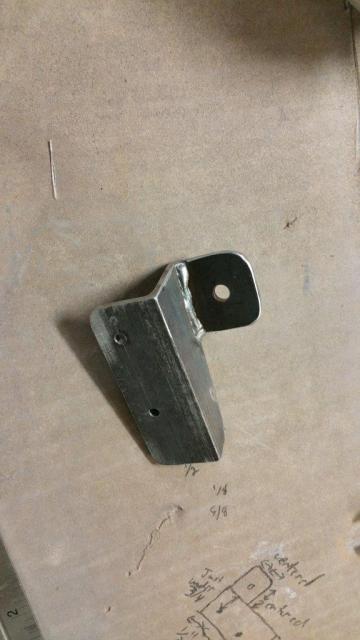
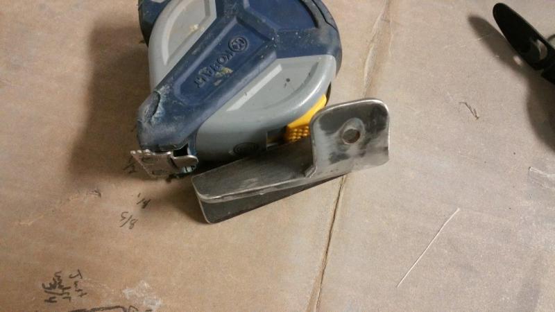
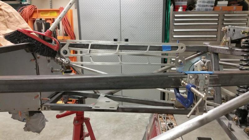
Finished the hood mounting brackets yesterday. This stuff is time consuming to get just the right angles etc. In case anyone wants to do something like this. The top mount is also 1-1/4" 1/8" thick angle iron. A bit thinner could be used, but this is what I had. I chose steel because I can weld it. Bending something out of aluminum would be really hard to get right. I chose to use the hood clamp bolts to hold this. It also adds reinforcement behind the hood latch. However. you could drill holes in it and then fiberglass it to the inside if you needed to. I made them 3" long. You could go a little shorter, since there is really not too much stress on this point. I took 1/8" off the bottom of the angle iron so it would fit within the body line better. The mounting tabs are 1-1/4 wide x 1-1/8" tall. This makes it 1-1/4 x 1-1/4 once you weld it to the top of the angle iron. Mount the angle bracket to the hood before trimming the top. With the hood closed, position the hood props where you want them with the bottom bolt snug. Attach the mounting tab to the prop and let it rest on the top of the angle iron where it wants to be. Make sure the hood props are perfectly straight and not bent for this step. Then just tack the mounting tab to the angle bracket. This is the easiest way to get the right angle. Then I removed it and rounded it up and ground the excess off the top part of the angle. Now that it is done. I will have to buy the right hardware. This is just temporary 1/4-20 stuff. I will use proper length stainless socket button heads and nylock nuts so I can set just the right amount of tension, be the correct length, and look better.
-
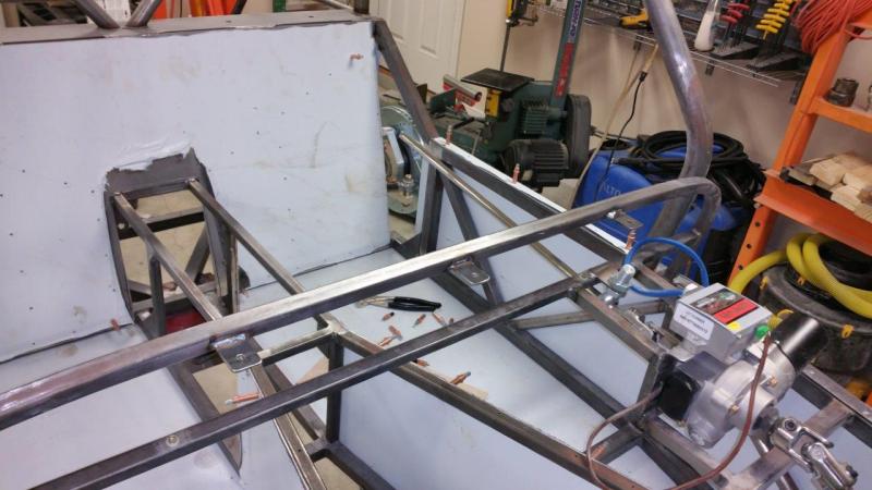
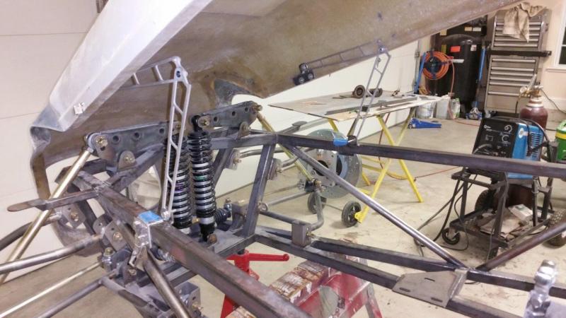
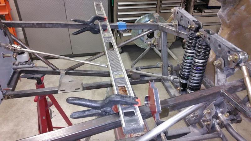
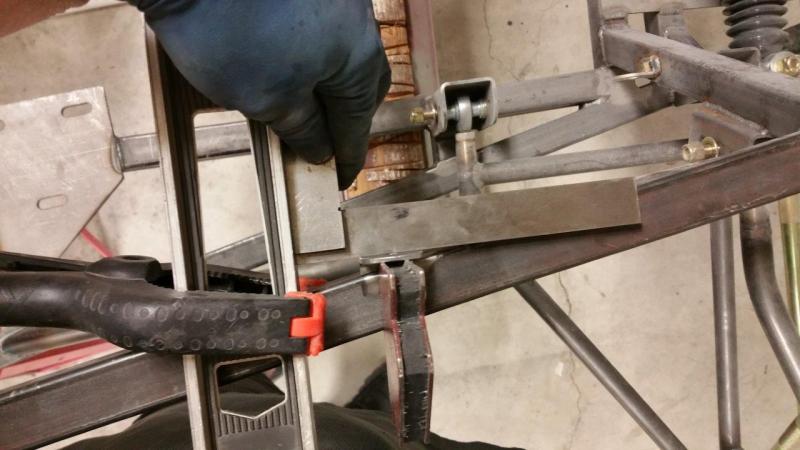
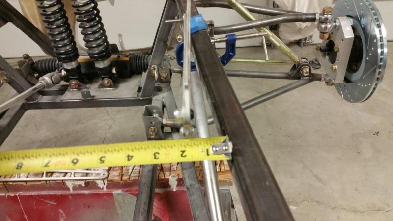
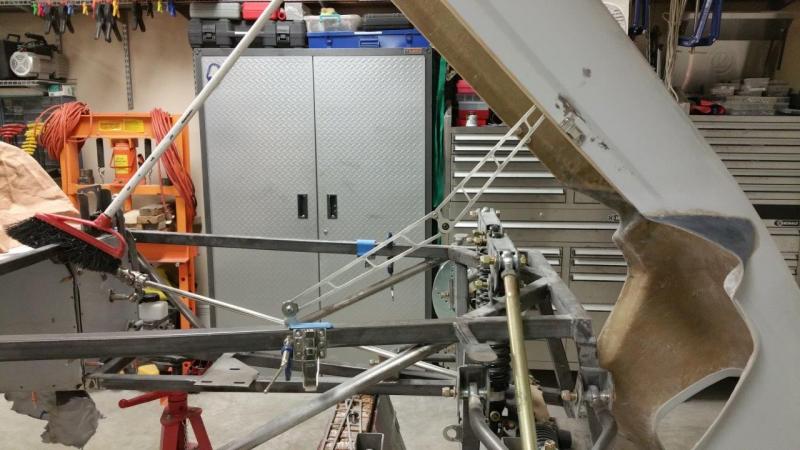
Fabricated and welded on the lower hood prop brackets. I used 1-1/4" 1/8" angle to make them. Aligning them was quite time consuming. They need to be perpendicular to the front tube, but none of the tubes on the right side are perpendicular and only the inside lower tube is on the left side. So, I just measured off the front and precisely clamped a level in place that I could measure and square off of. I will get some nicer looking hardware. Socket button head most likely. I am not sure if the prop will be mounted to the inside or outside yet. I have to see how things work on the hood. The hood ones will be a little more challenging.
-
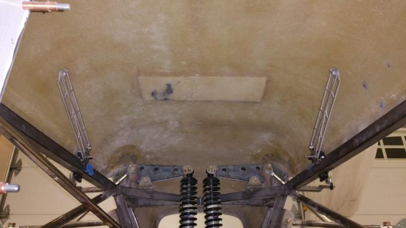
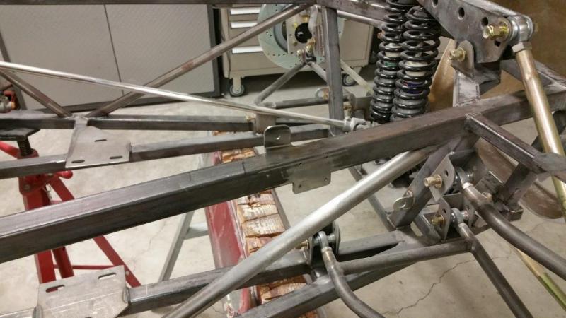
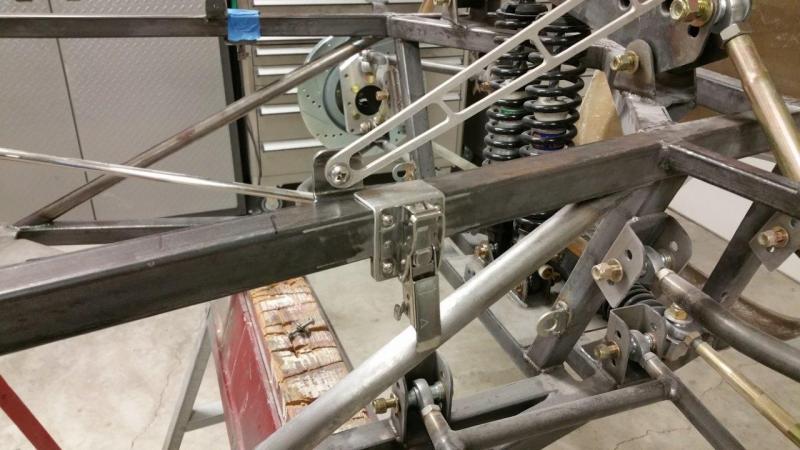
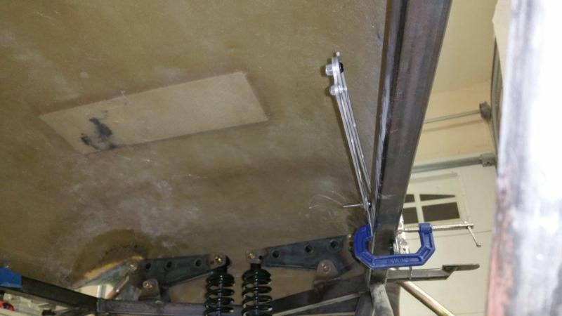
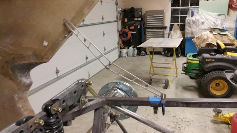
Couple more pictures. Yes they have to stick into the engine bay a couple inches in the back when closed. They have to be perpendicular to the hinging (and the rails are at an angle). THey are above the rail and behind the hood when shut though. As long as there is nothing there when the car is done, it will be fine (waiting for toedrag to comment).
-
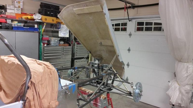
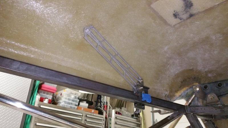
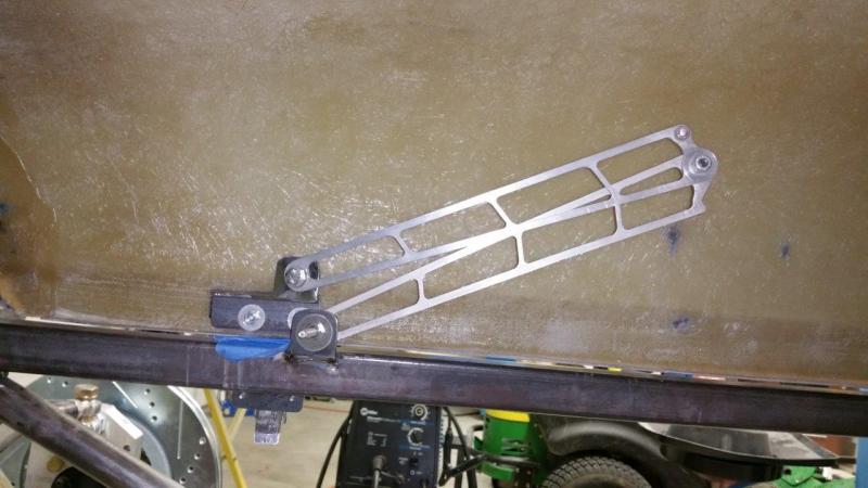
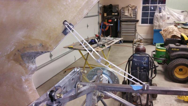
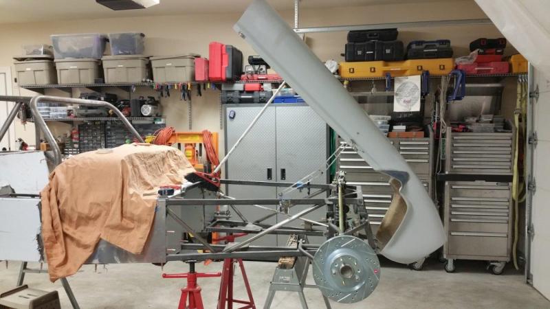
This is my idea on the hood props so far. This is just a mock up. Since toedrag is farther along, I sent him some pics to see if there would be any interference issues. Seems like it will work to me. Anyone see anything they don't like? Of course there will be one on each side. I will glass in a metal bracket to the hood for the top mount and weld a proper bracket to the frame for the bottom. The only issue I see is that these things are built super light. However, even if the wind caught the hood, they would not let go and they would not be able to let the hood fall even if it blew forward and then came back down. It could bend them though. Of course if that ever happened I could make stronger replacements, they would just be a little heavier. Also, do you guys think this is open far enough? I can make it open as far as I want, but much more than this and there won't be much weight on the props and at some point it will actually be pulling forward.
-
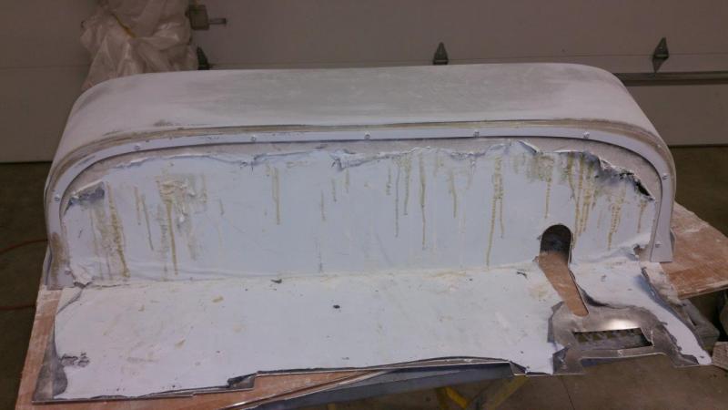
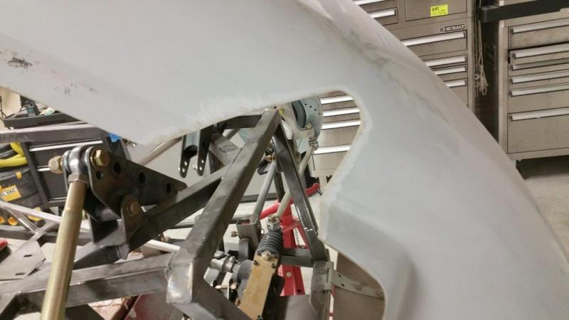
They already did something about the same on the green one they built. They don't seem to be doing it on the hoods for the do it yourselfers though. They just leave that unfinished looking cutout. So, I more or less copied them. They must have done theirs about the same way I did mine by the looks of it. I did not ask.
-
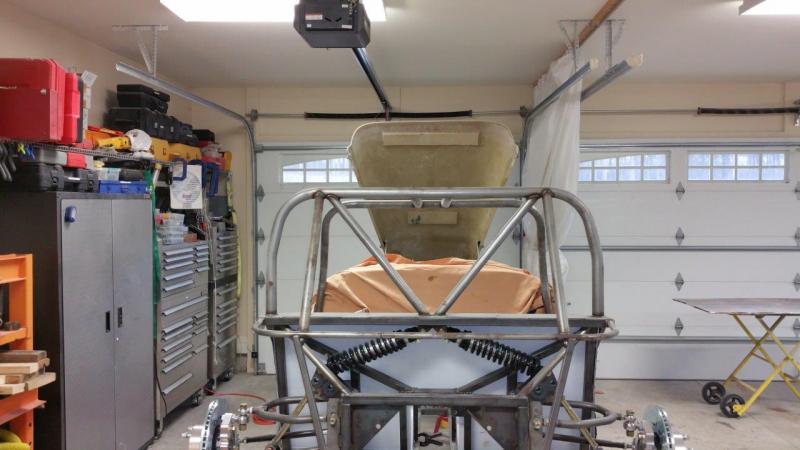
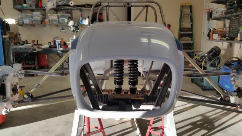
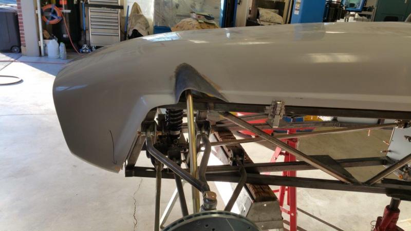
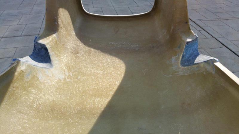
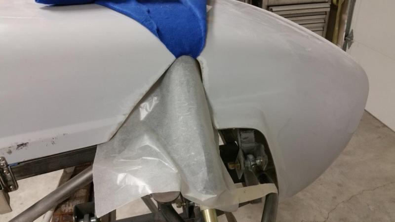
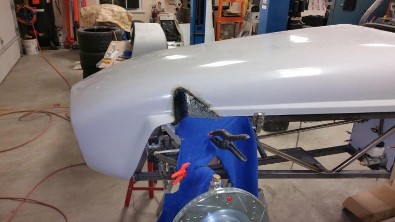
Shaped the rocker rod "hoods" today. Luckily it was nice enough to sand outside.
-
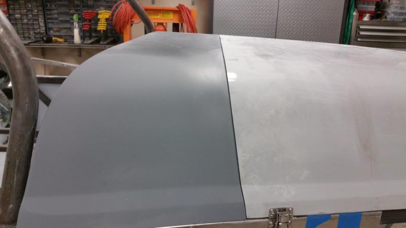
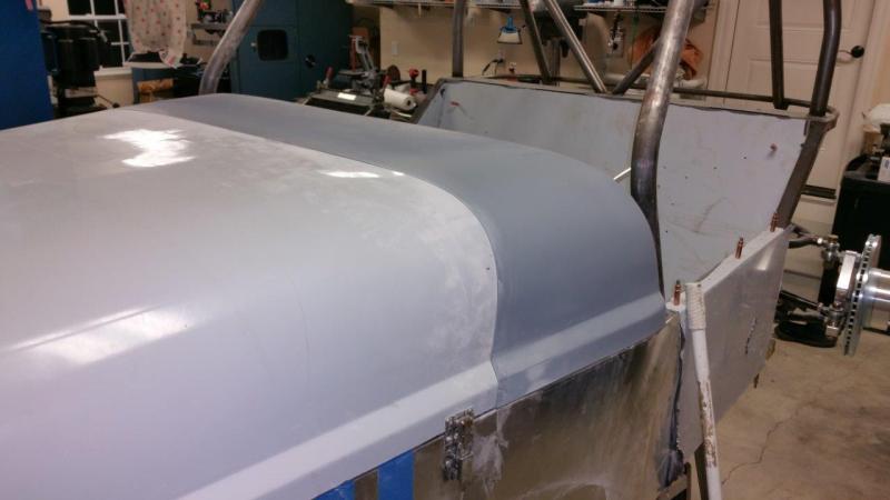
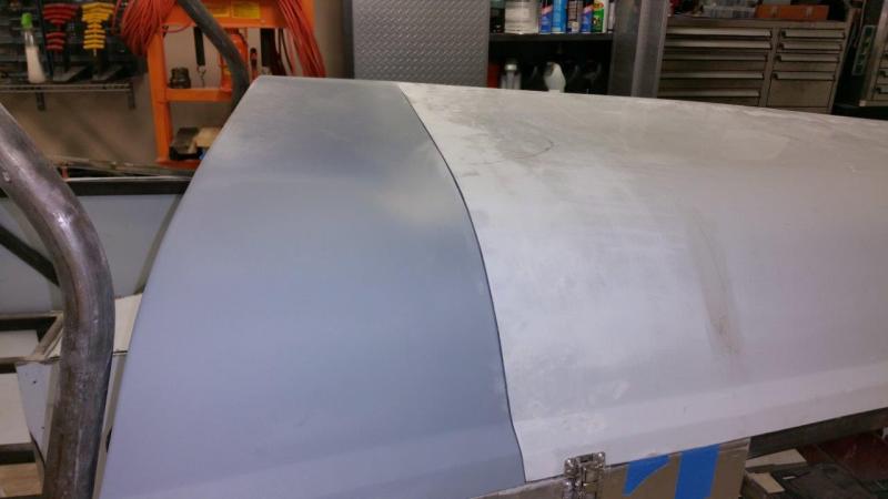
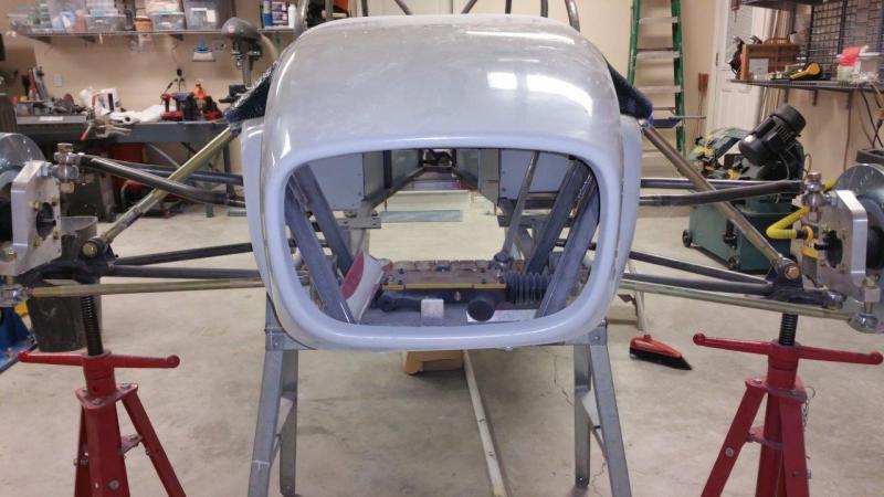
The messy work is finally starting to pay off a little. The mate between the hood, rubber gasket, and scuttle are finally good. There is still a lot to do, but this stuff should be easier. I have to add some mounts for the dash side of the scuttle, make the body lines actually line up (they are terrible), trim and smooth the little rocker arm hoods I made, sand the final hood to scuttle body gap, and then try to get all the dips, bumps, and waves out of all this.
-
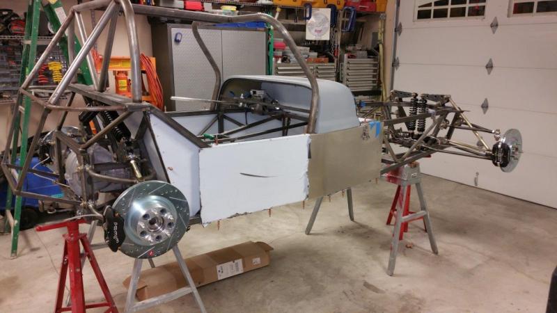
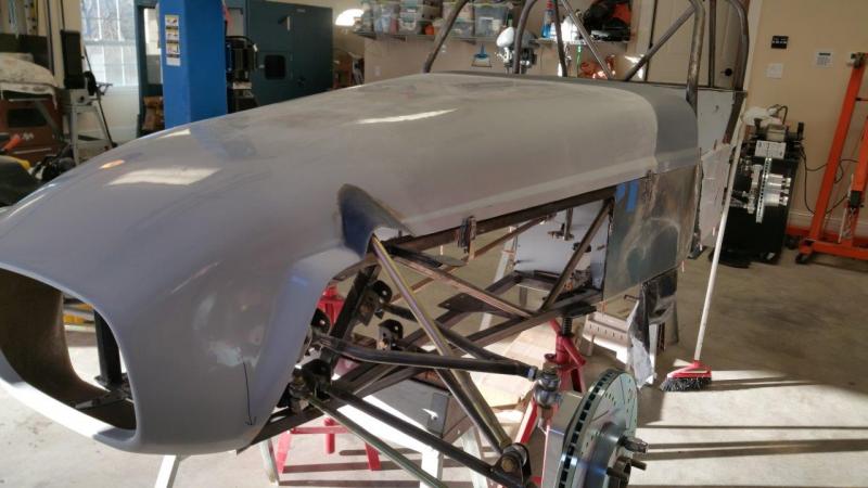
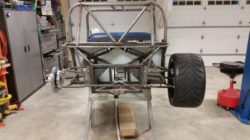
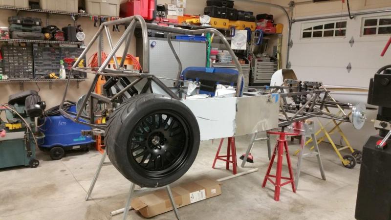
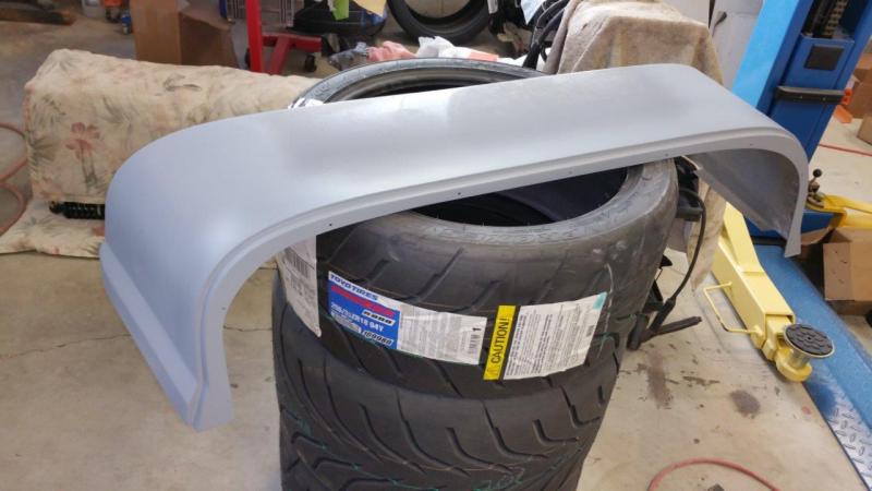
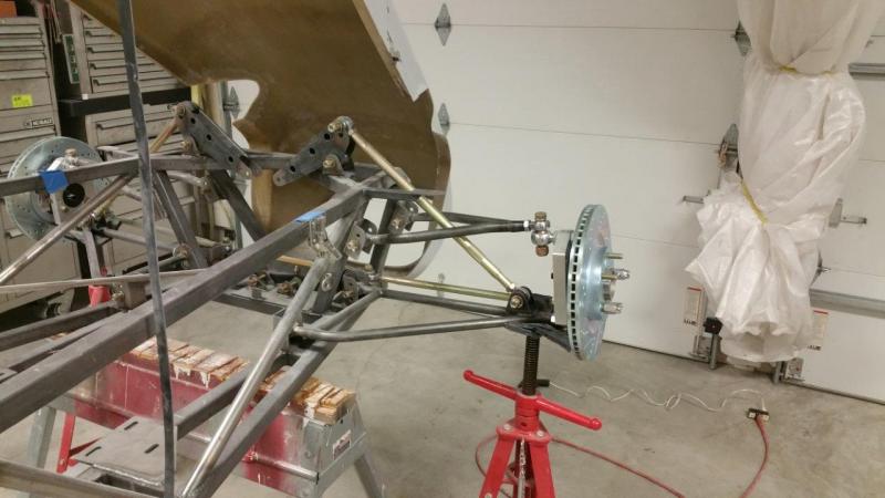
I finally finished up a bunch of other projects and had the rest of the afternoon to mess with the car. Hopefully I can work on it a little more regularly again. I had to bolt a wheel up just so I could look at for fun and make sure everything did bolt up ok. 315/30-18 11" wide wheel with +20mm offset using 1.5" spacer (Brunton recommended sizes) I sanded down the fiberglass I added on the bottom of the hood edge. The thickness is a bit more consistent now and the mate to the rubber will be smoother.
-
For the final height adjustment and corner weights you will want to get it on some scales. You may also want to sandbag the seat for your weight when you do it...However for doing the body work, you can just get the ride height about where you want it and then try to tune it back to about that on the scales with your weight in there. Personally I would not put a bunch of effort in figuring out the preload amount and all that because it is going to need tweaking once you get it on some scales and put your weight in it and finish adding weight to the car. This is why the front is nice, no fender placement to worry about regardless of what happens. You can move the front suspension anywhere with no worries. I have not messed with the rear fenders yet, but if you could somehow slot them or leave larger holes and use fender washers or something and leave yourself some adjustability for final tune, that would be nice...
-
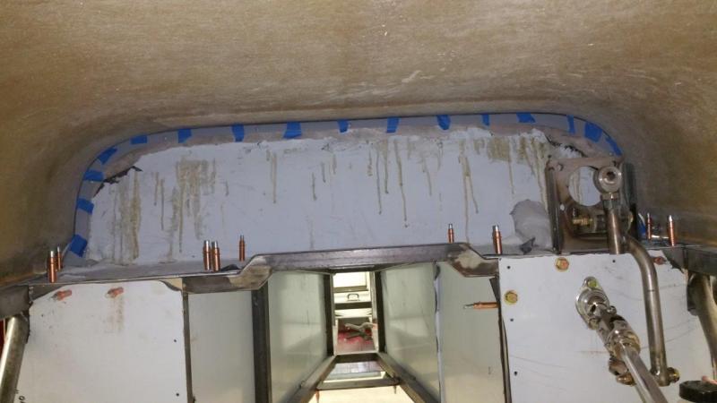
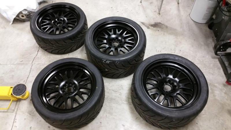
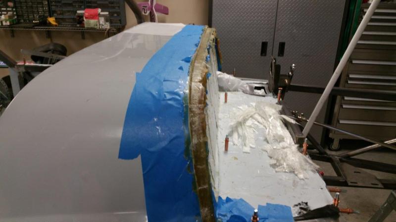
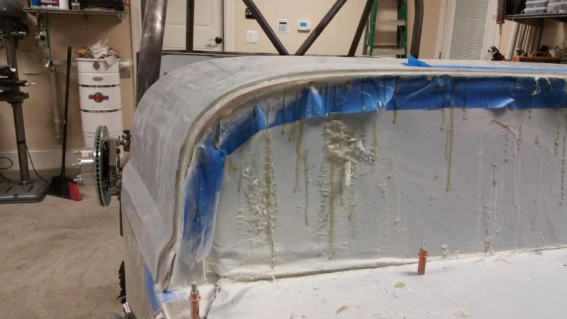
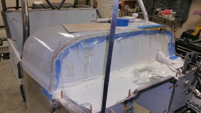
I have not worked on the car in quite some time due to a lot of other projects that needed to be done. Here are a couple pictures I did not have time to add. I did finally get my wheels that I ordered 6+ months ago. Hopefully I will be back to the car soon. I finished most of the other things up that I had to get done. I bought a new 16x40 lathe and this required me making a lot of rearrangement to the shop to fit it. I also had to find room for yet another set of tool boxes. I had do a little rewiring and the lathe itself needed a lot of tweeks. I also had to install a snow plow on my zero turn mower which of course required some custom fabrication, welding, refinishing for the "universal fit" system. I got the scuttle lip remade and primed. There will still be some straightening on the top and sides, but I think the hardest part is over. I also have to make and glass in some mounts on the bottom of it on the dash side. I will be welding some tabs to the dash tube. It is way too flexible in that area and needs to have some solid mounting points or it will just flex up and down constantly and rub away the "carbon fiber" dash over time. I finished the glassing on the "hoods" over the rocker tubes. Those just need to be sanded, trimmed, and imperfections filled, etc. I also added some glass to the inside lip of the hood. The thickness was not consistent. This will need to be sanded so the lip mates to the scuttle well and being smooth will be easier on the rubber gasket over time. It will also have consistent strength. It was pretty easy to flex it in a couple thin spots.
-
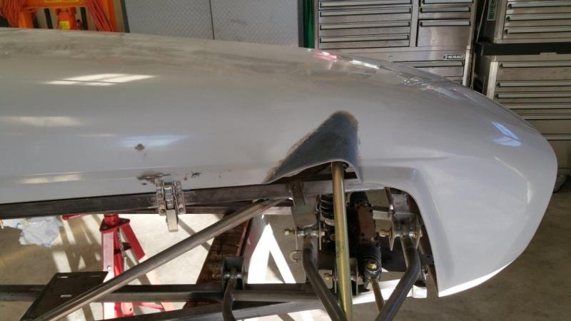
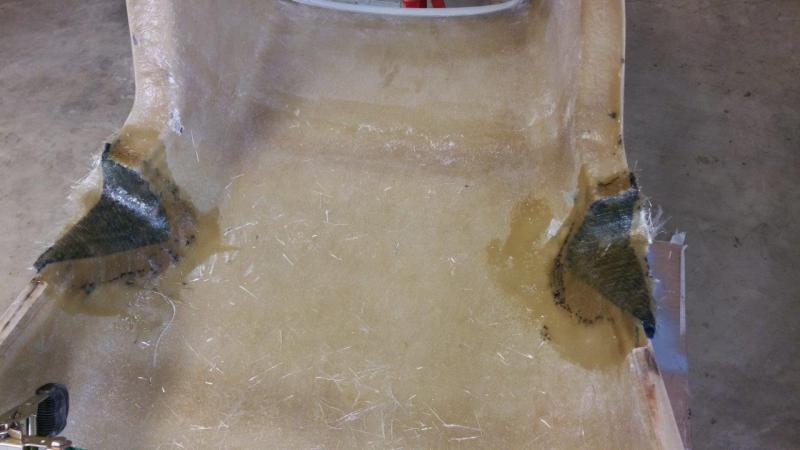
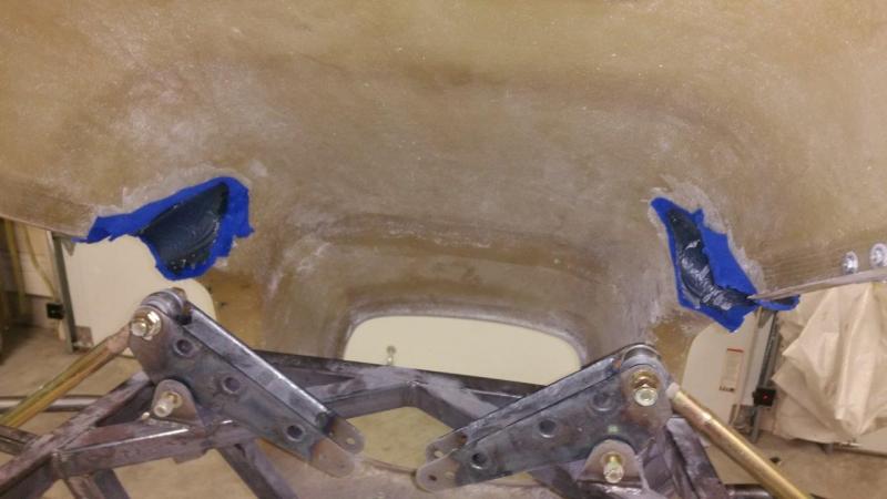
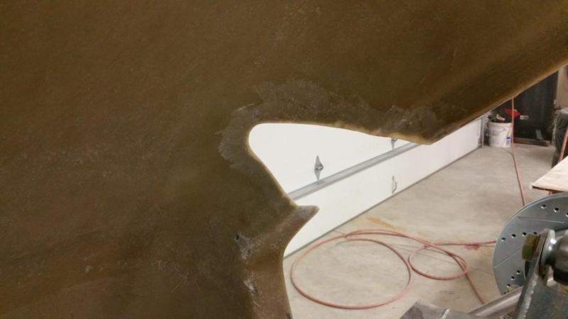
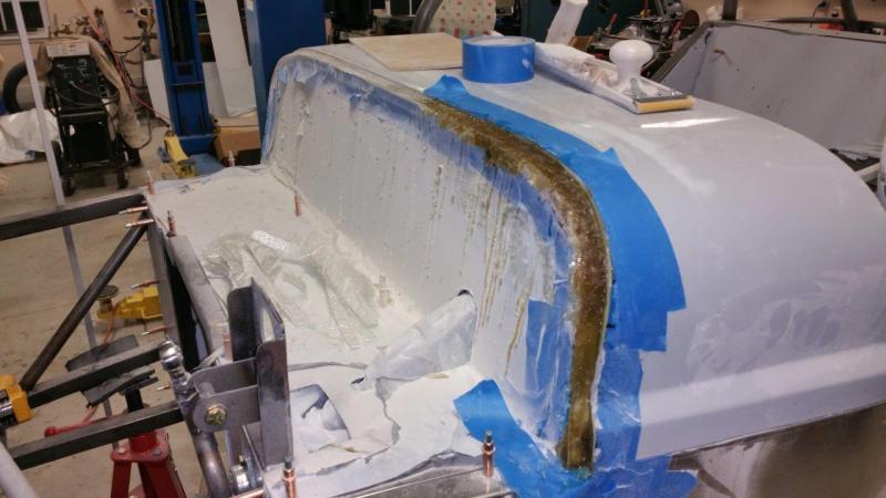
I used wax paper again so the resin would not stick. I stretched some fleece that I had leftover from another fiberglass project to make the shape. I used dabs of hot glue to hold it on the back side here and there. I believe this is probably about the same method Brunton used to make them on the green car (based on the same shape I am getting), although I trimmed the lips in front of these on each side to be about the same width first. Next I coated the fleece with resin and added some small strips of fiberglass for filler where the fleece meets the hood. Next I will have to trim them to shape, add a couple layers of fiberglass to the back side, and a bunch of sanding and some filling to get it all smooth. Can't wait to get back to the mechanical/electrical stuff. I hate the mess of body work.
-
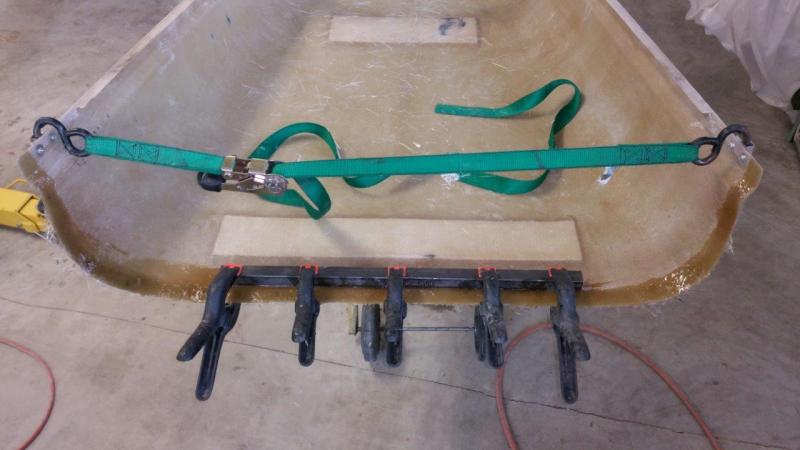
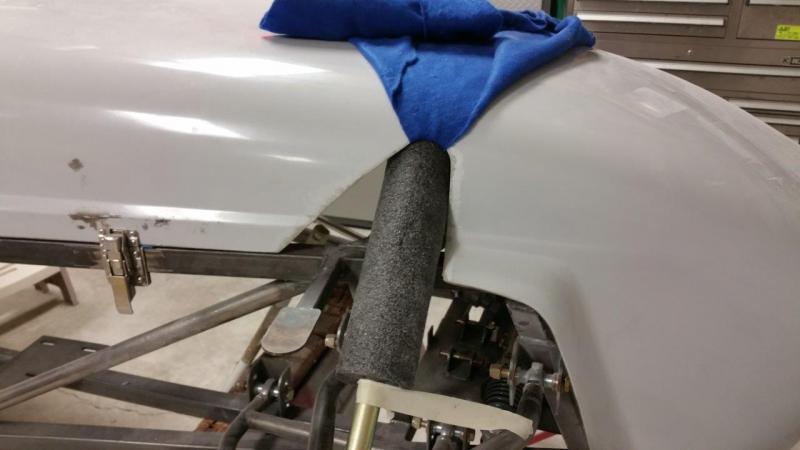
Well I have been doing body work for many evenings and some days now. I think I have the scuttle lip finally ready for some high build primer. Trying to work on one thing does not work well when you actually get a whole day to do something. You need something else to do while the other thing dries. So, I decided to go ahead and add the rocker rod "hoods" to the hood. I ground the back side a little and ground the gel coated side edge down to fiberglass. I then removed the shocks and moved the rods to the most interfering position. I used a piece of pipe foam for a form.
-
I will most likely fiberglass an angle bracket into the hood and then weld one on the frame. Not sure of the exact details until I can get to it. I am debating on doing it soon, or waiting until the engine is all in so I can check more than pictures for clearance.
-
Please elaborate on what your doing with a battery isolator? Are you using a lower current handling switch with smaller wires to turn off this isolator or something? I cannot comment properly without knowing, but this method might not be "race legal"...of course I am just speculating since I don't know what you have there. I don't believe you can use secondary devices like relays etc since it is not as safe as a 100% direct mechanical disconnect at the cutoff switch. My plan is to put the cutoff switch in the dash on the passenger side which is right behind the battery. This is not perfect. It would be better on the outside of the car within reach of the driver, but this is pretty darn close to good. I have seen others do this. You can still reach over as the driver, and it is just inches from the outside for a safety worker to get it. Of course I will have no roof or doors
-
Using a wire for a longer ground than just going to the closest point of the chassis is not necessarily better. You’re limiting your current flow to the size of that wire for that length. This has more resistance to flow than a gigantic lower conducting chassis "wire". Your also making potential differences of your grounds. The chassis will all be the same, but each length of ground wire will have a different resistance and therefore a different voltage due to the tiny resistance of the wire. The more current you’re trying to push through it, the worse it is. If you were going between parts that were bolted together and/or separated by paint with only fasteners that break through and conduct, it might be different. For example, you might not want to ground something in your door to the door, or to the hatch of the trunk etc. (not that we have those). Your chassis is a single ground point and a massive "wire". Take your ohm meter and measure from one end of the chassis to another. You will measure near zero. The difference is you’re not pushing the electrons down a wire; they can go over the entire surface of the chassis. They will choose their own shortest path. If you were running audio equipment, it is a little different. You have to be very careful of potential difference so you don't get a ground loop that induces noise. You would want to ground all those to the same point on the chassis with as short of wires as possible. The more distance between the components grounds, the more potential for “antennas” and voltage differences due to different lengths of wires etc. Your also not passing data through your chassis, if you were, then you would wanted twisted pairs, ground jacketed wires etc.... Simply supplying power to a headlight or a fuel pump won't really matter. Also, the longer you make your battery ground wire, the more your restricting things. Getting it to the chassis in as short of a piece as possible is a good thing. You also have to consider that many of your electronic devices are regulating the voltage themselves. They don't need the full voltage of the battery/alternator. They will regulate down to 12V, 5V, or whatever they need and "ignore" anything higher. Anyway, my point was, there is no need to over complicate it on a car. Most/all ground problems are caused by the terminal used to connect to the chassis or an issue with the wire being used, not the chassis itself being used as the ground. People that have engine problems usually do not have an adequate connection to the ground (chassis). They did not remove the paint, use a heavy enough gauge wire, etc. Adding more and longer wires to the system actually adds more potential for problems. It also adds weight. Of course there are many ways to skin a cat..so to speak. The shorter the wires to the chassis the better. A wire won't conduct as well as the entire chassis even if copper is a better conductor, unless you way oversize all your wires, and then you will have vibration and mechanical issues to deal with over time and create more ground problems than solving. Keeping it simple and putting your terminals on correctly and sizing the wire used is most important. Oh, another thing to note is that if your going to use bus bars in the rear and then connect up with a larger wire. Every connection point adds resistance and a potential failure point. In the manufacturing world, these would all be six sigma quality no no's. All of that will not be any better than a 3 inch wire right to the chassis, and more potential for problems. Also, don't forget that your engine is moving and vibrating. Making your grounds all go to this vibrating monster is not necessarily good. It will work I suppose, but every car I have ever worked on grounds the engine to the chassis, not the other way around. I have worked on about every brand of car at some point and all those engineers must know something. I do have an electronics degree....I will be using the shortest wires to the chassis for ground points. I am not completely pulling this out of thin air for the most part
-
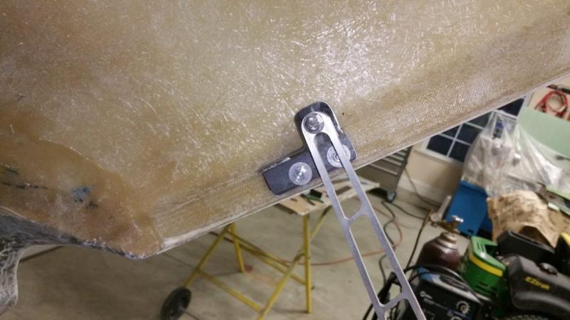
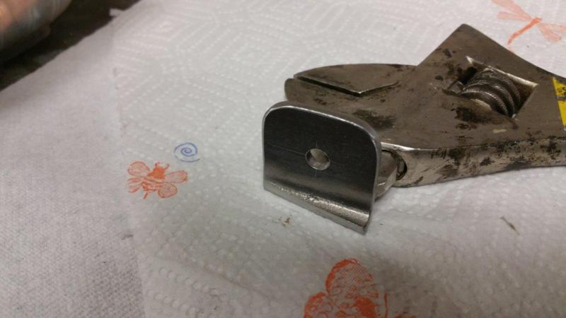
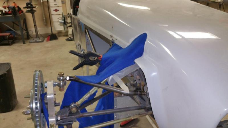
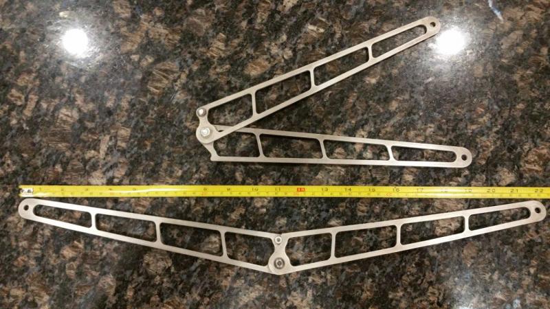
More pics of the hood and scuttle work. I scored some Nascar hinges off eBay. These things are only 3.4 oz for the pair and they act as hinges and they lock open. These are longer than any others like this that I could find. They are one offs, so sorry, no link. Not sure what team made them. These will act as my prop rods.