jevs
-
Posts
316 -
Joined
Content Type
Profiles
Forums
Store
Articles
Gallery
Events
Library
Everything posted by jevs
-
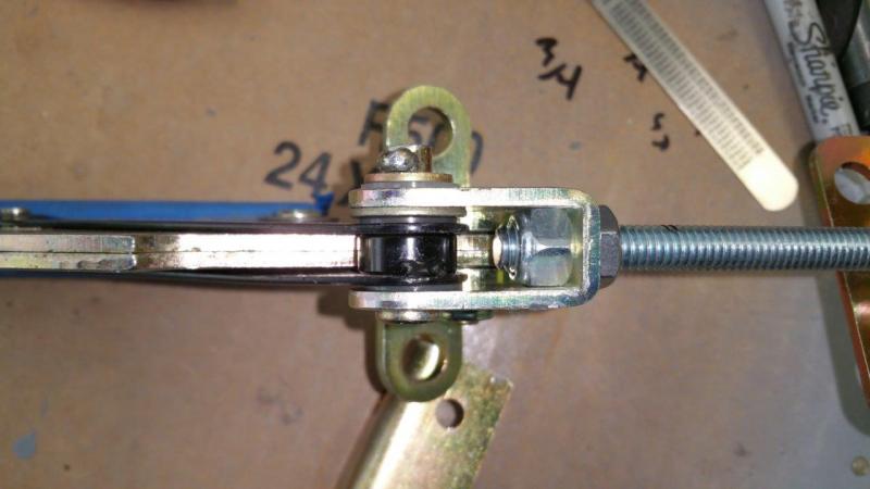
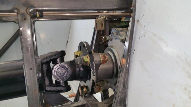
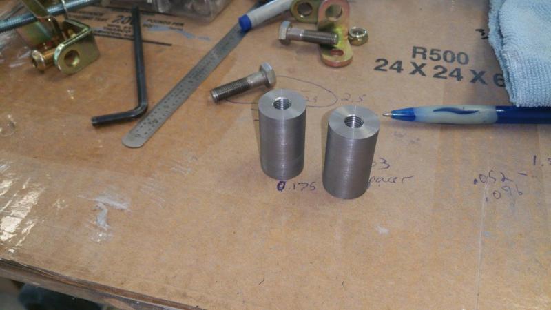
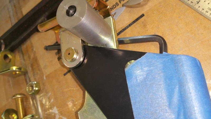
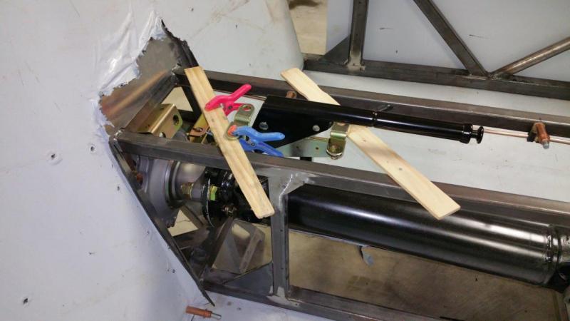
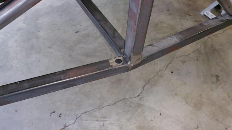
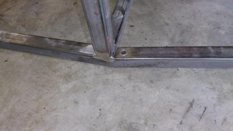
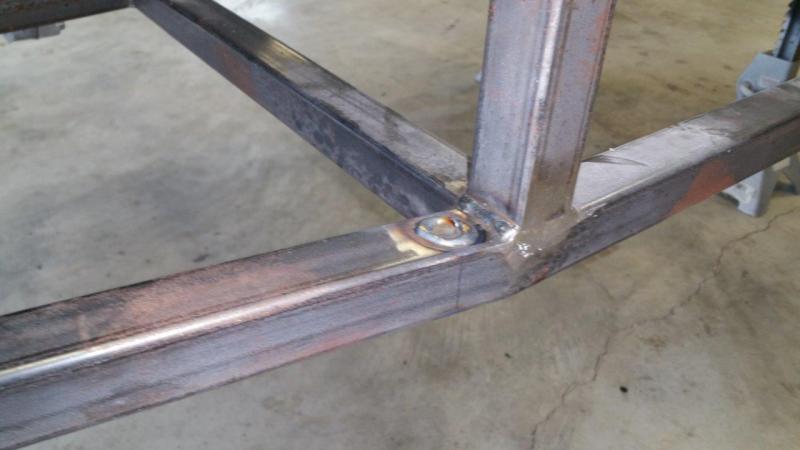
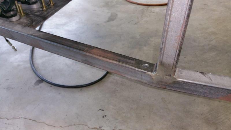
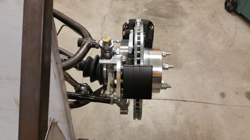
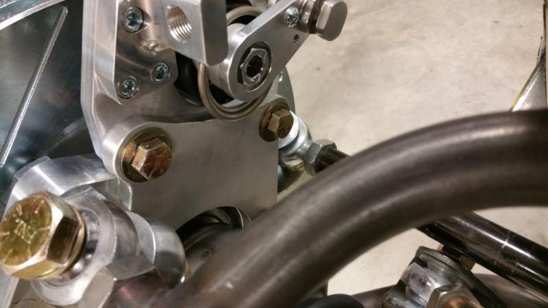
Finished the parking brake setup minus cables. Drilled out the clevis to take a 5/16" rod which already fits the cable pull part. The clevis captures a nylock nut just right. There is a nut on the other side as well to lock it in. This way you can adjust it by just turning the nylock nut on the part that the cables latch into. I added some nylon washers and a metal washer to the clevis so there is no slop in order to reduce rattles. A plate was welded in the back to mount the cable holder. This gives a clean shot through above the differential. It is mounted with ¾” button head bolts so there is plenty of clearance for the cables. This setup allows you to remove the cable bracket just in case it is in the way of wiggling the differential out or anything. The spacers for the hand brake were made on the lathe and tapped to 5/16-24. The spacers were then welded to the frame tube. The rear spacer needed a little notch so the hand brake could come down fully without touching it. There may still be enough room to pull the driveshaft out the top, but I believe it will come out the bottom anyway. This setup is very solid and only requires two bolts to mount the hand brake. I will put the tank in and then figure out how long the cables need to be and get them ordered.

-
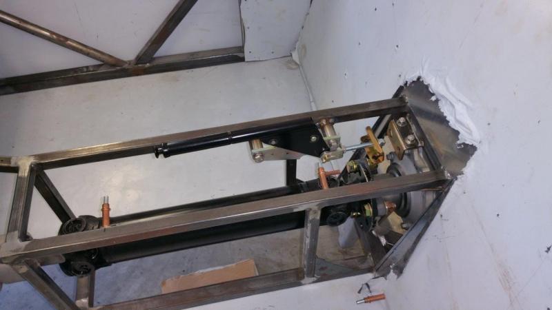
Putting it in the tunnel for me and having my parking brakes flipped right to left from yours with the cable connecting point up top is going to make the cables a pretty nice straight shot on nearly the same plane with just a curve back to the brakes I am hoping. I am trying to keep the cable routing around things and bends as minimal as possible. I would consider the back panel, but now that I tested it where it is, it does not touch my arm at all. I could pull it while driving if needed. Of course nothing is set in stone yet. I will hopefully be looking at it more seriously this weekend and making some progress. I have to get everything in place without cables since I am having custom made cables with no screw clamped ends. Hopefully I can get the lengths right on the first try. Right now I am considering making some threaded steel spacers that weld to the passenger side of the frame tunnel. Then the handle assembly will just use 2 bolts to attach nice and clean and simple without all those L brackets they want you to use totaling 6 nuts and bolts to get it all mounted. Attached a pic to kind of show what I mean about the lines staying on nearly the same plane without going around anything.
-
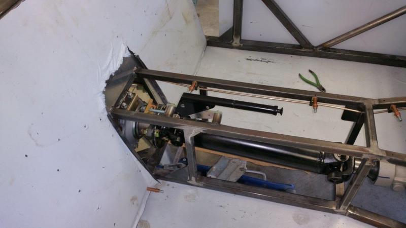
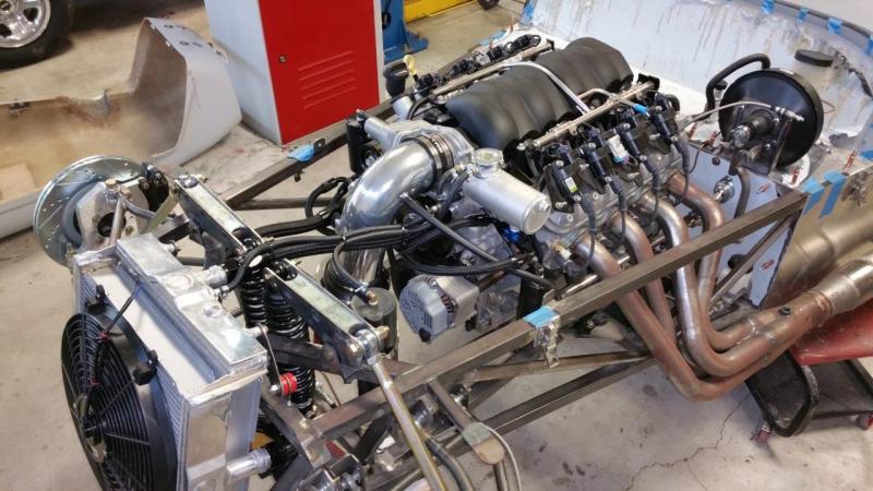
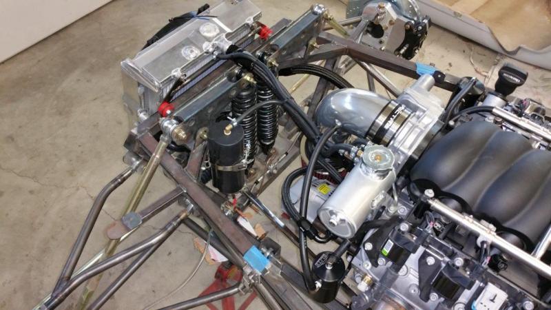
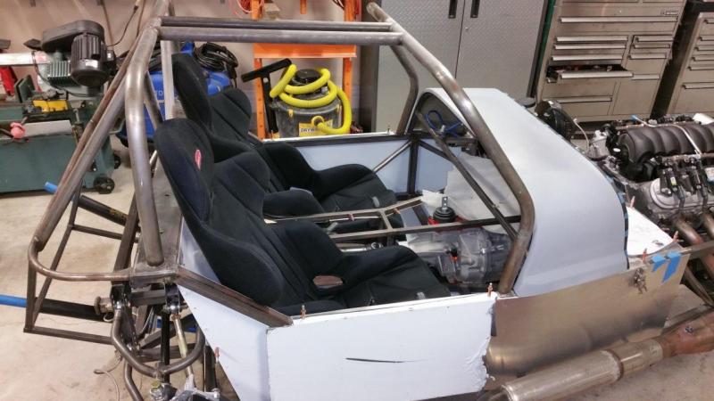
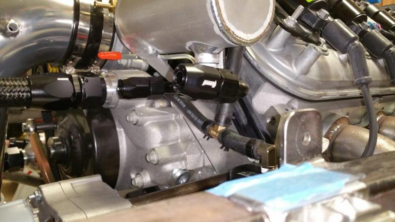
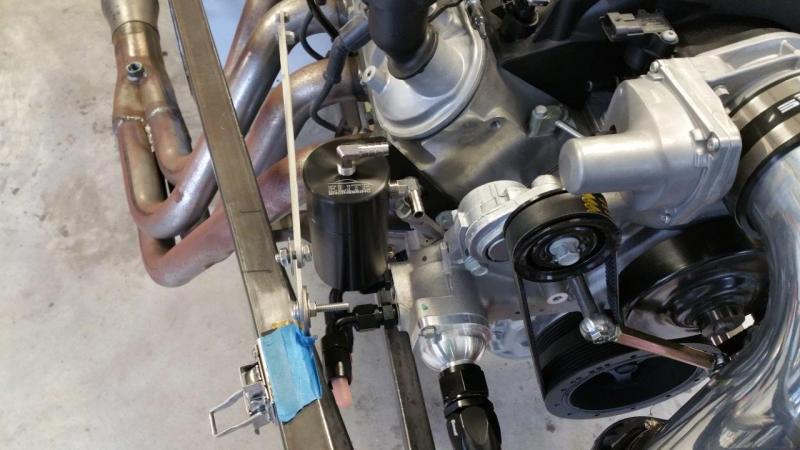
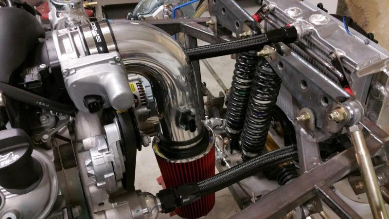
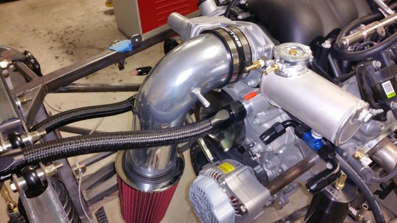
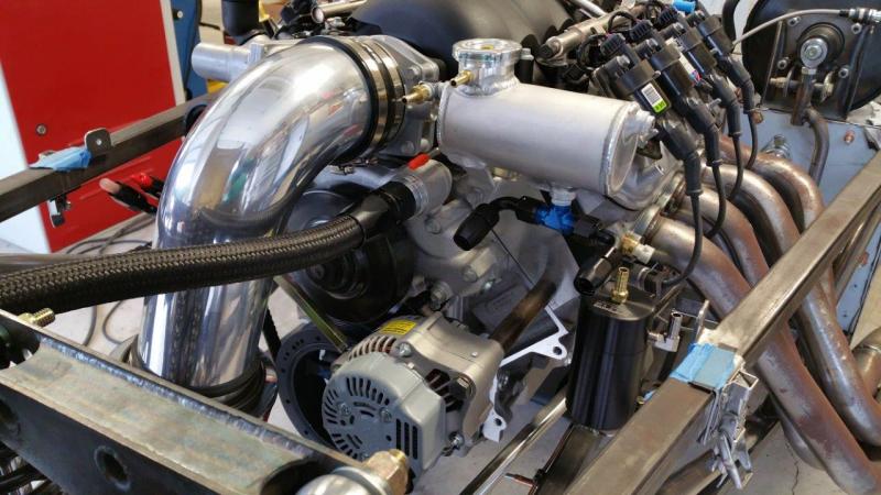
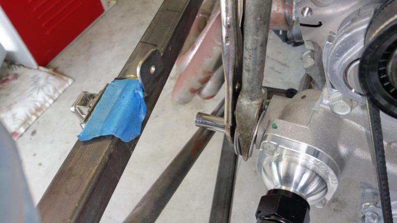
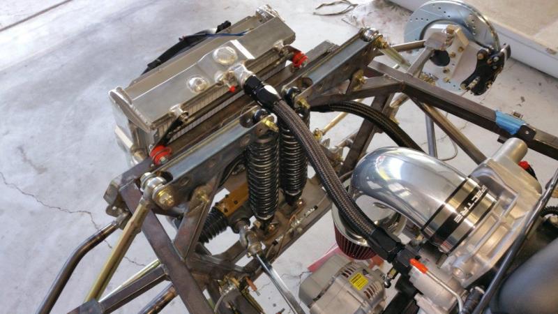
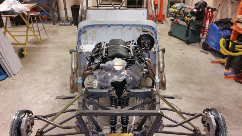
Cooling system and catch can stuff all done. Anyone doing this setup with a surge tank should know that the catch can connected to the surge tank should not be plumbed as a recovery tank. The hose should go to the top of the can and always be open to air (the catch can has a small air hole in the top). The hose should not be submerged internally or connected to the bottom of the tank. This tank only serves one function and that is to catch any fluid that comes out of the surge tank when something goes wrong (over heating, over filled surge tank etc). Once your surge tank has settled in and has the proper air space in the top of it, nothing should ever come out into this catch can. It is not a recovery tank like you see on most normal cars. Those do need to suck fluid in and out in order to maintain a full radiator because they don't have a surge tank setup. You don't want to make a fluid trap in this setup that would force the surge tank to suck fluid in and out. You don't want your surge tank to ever be full. You want your steam ports venting into the upper air space. If you make the catch can a recovery tank and it gets fluid in it, it will cause the system to not really function as intended. Eventually it could burp all your air space from the surge tank and it will just stay full. You may never see an issue if the catch can never gets fluid in it, or you never push the car hard or make steam from the steam ports etc, but it won't really be right. In fact you can run without the catch can at all if you want. Many people just put a hose down to the bottom of the frame. Once the system is stabilized, it should never really do anything. The catch can should not be an active part of the cooling system. It is just there to keep the EPA happy & the race track people happy if you should ever overheat or run so hard that it needs to burp a little. I also mocked up the parking brake a little and set the seats in to see if it was going to hit my arm. This location seems great. It will be pushed over to the passenger side as much as I can. I have an idea on mounting it nicely. This was more just to see if it was going to be an issue with arm clearance and spark ideas on the placement. I kind of need to think about the parking brake cables at the same time as the fuel system so nothing gets in each others way.
-
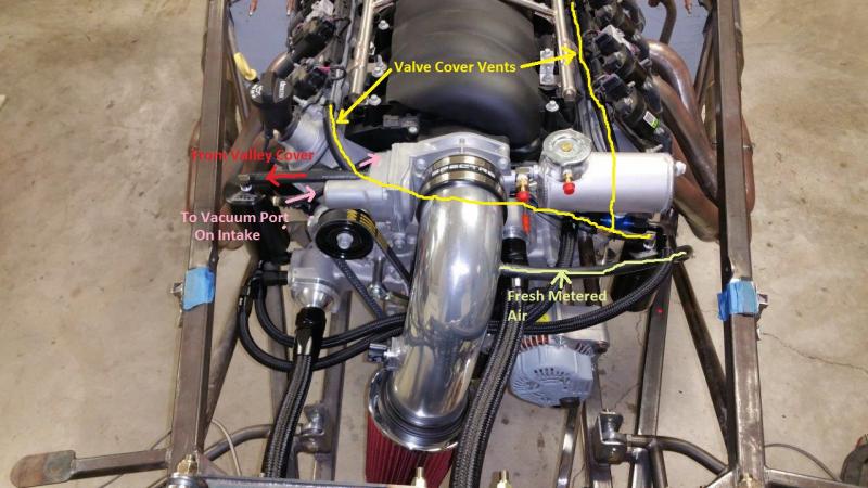
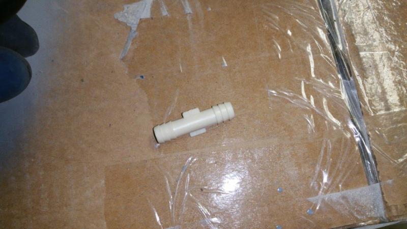
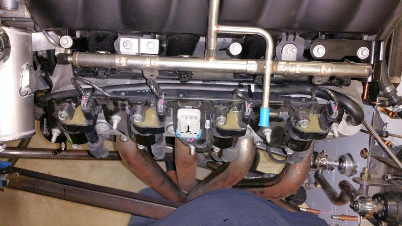
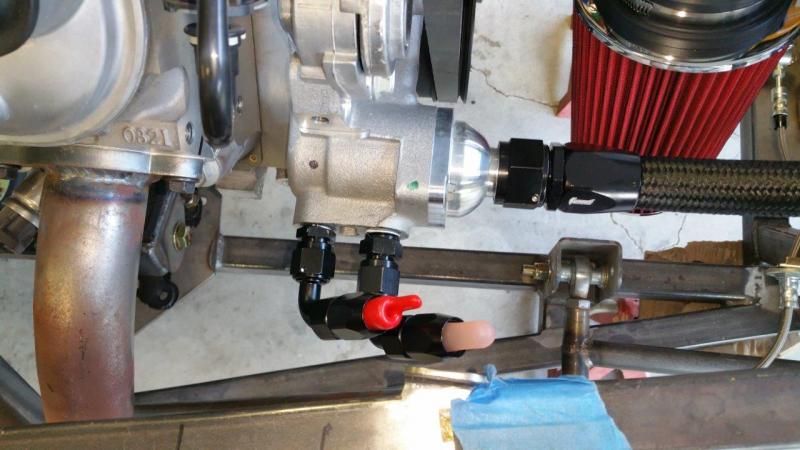
Finished the venting and catch can setup. Straight hose would not make the bend nicely on the rear drivers side valve cover fitting without sticking way up. I found a hose in my hose tub that had the proper bends and joined it in with a straight barbed fitting. The passenger side catch can just takes the place of the U hose to catch the oil that would normally spurt out of the valley cover and suck back into the intake to be burnt. The drivers side catch can is only there to catch anything that might burp out the valve cover vents. Normally this gives fresh air, but at times it could potentially burp back out into the intake. This prevents that. Technically you could plumb your motor just like this without the cans and it would be fine as well. You would just be burning the oil instead of capturing it which is basically what a stock motor does. We will see how much these capture. This will keep it from gunking up the intake and valves. I also got the surge tank to water pump lines made.
-
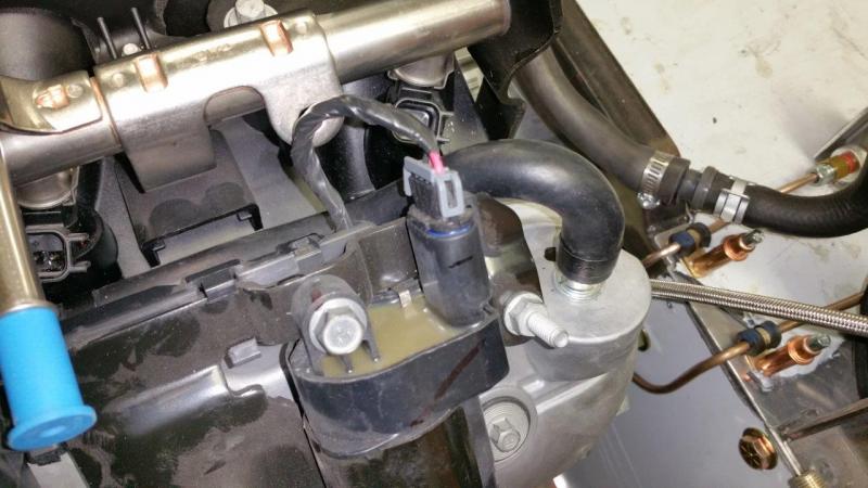
I was able to mount the passenger side catch can without any mods. I just put it as low as it would go in order to have enough clearance for the hood hinges. I welded the MAP sensor bracket into the intake. I also made a nipple and welded it into the intake for the clean air supply to the valve cover vents. The intake was sanded, scotch brighted, wet sanded, and buffed back out so it looked decent again. I will finish up the PCV hoses and the coolant hoses next.
-
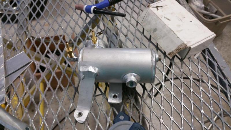
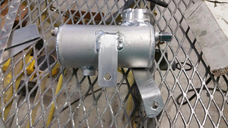
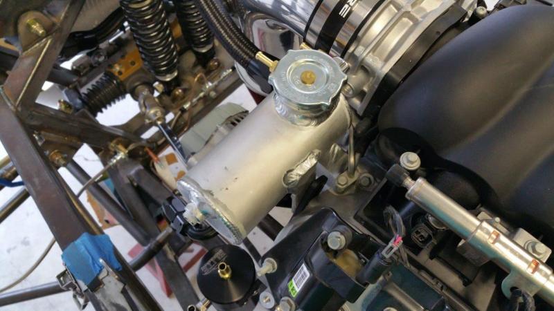
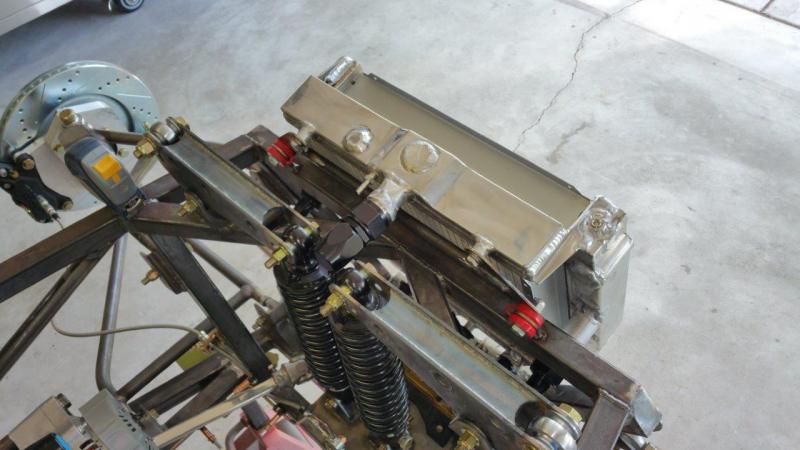
The surge tank has been mounted. I made two tabs and TIG welded them onto the can. It is rock solid and will not move from vibration or flex around when your trying to unscrew the cap. It had been a long time since I used my TIG welder, but I did recently buy a new pedal for it because I knew I was going to have to do this. I previously had a thumb wheel on the handle. Don't ever buy one of those. They suck. They might be ok if you had to get somewhere that you can't uses a pedal, but controlling the current is much harder. There may be better ones, but the miller one is too cumbersome to use. It is hard not to dab the tip in the puddle when your scrolling the wheel with multiple strokes to control current or shut off the arc.
-
Had to remove the two tubes from the water pump. I clamped a socket in the tube and put vice grips on. I then used some spacers for protection and hammered my wedge in to pop them out. 3/8" and 1/2" NPT Taps are needed to tap these out. The holes are already in the right size range so that no drilling is necessary. You can vacuum out the shavings and blow air from the inside out afterwards with the thermostat housing off. I capped off the drivers side vacuum port where the evap system would normally be connected. I played with different mountings of the drivers side catch can and ended up drilling one hole in the bracket and mounting it like this. It clears everything including the hood hinges. I did not want it to share the alternator mounting because my spacer for the alternator is machined on both ends to keep it as straight as can be. Also using that hole on this side head makes the can crooked anyway. You can see I leveled the car up and made sure that can was mounted level side to side.
-
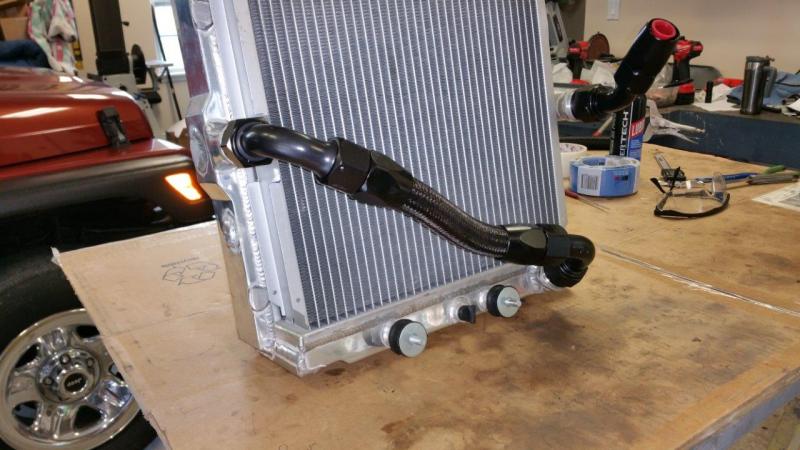
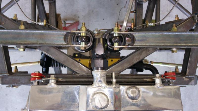
Mounted the fan. I used stainless button head screws and nylock nuts. I had to drill holes and dremel the center ribs of the mounts since the original fan hole are just slightly outside of working. I got all the large radiator hoses made and installed. I replaced two of the bolts in the steering rack with button heads just to provide more clearance. The originals were probably ok, but I like to have at least 1/4" clearance since it is rubber mounted down there.
-
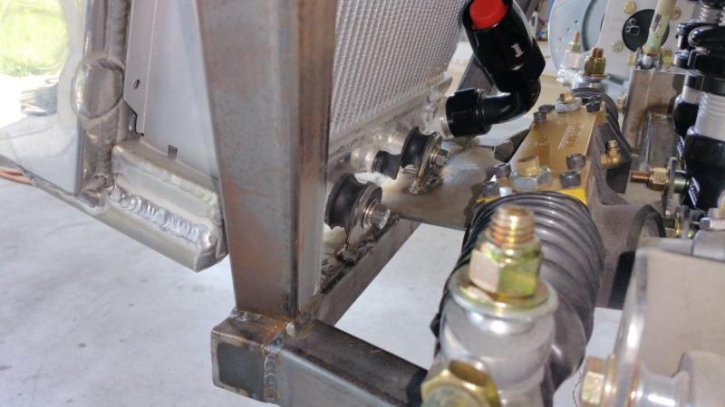
These are just junk ones apparently, but any of this style could potentially separate from force or aging of the rubber. This is why I decided to use the captured ones on top. In 100 years the radiator would still be captured unless the car was wrecked hard enough to break the welded tabs or 3/8" bolts. Also, luckily I had spares laying around. For once no part order was required With that said, I have one that came off a mid 80's Mini with everything rusted out and the rubber cracking, and it is still holding fine. So there is a big difference on who made them.
-
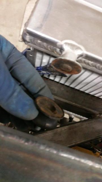
Brand new bobbin = Fail. I noticed the rubber was moving around the edges so I pushed on it a little and it popped right apart. I am sure there are better made ones, but how can you know for sure without stress testing for yourself. This looked perfect until it came apart and then I see what looks like rust in there and that there is hardly anything metal in there for the rubber to hang on to. I feel better having the top two snapper grommets. Never relying on rubber only to keep the radiator in place. I know one thing for sure. I would not buy these bobbins again. They are for Austin Mini exhaust hangers from Mini Mania. I have a stock one that is 30 years old and still in one piece even though the rubber is about shot. So not all are created equal. Not sure how you know you got a good one unless they are name brand from the USA.
-
Here is what I came up with. I am happy with it. http://www.usa7s.net/vb/showthread.php?9794-Brunton-StalkerXL-23-Build&p=94743#post94743
-
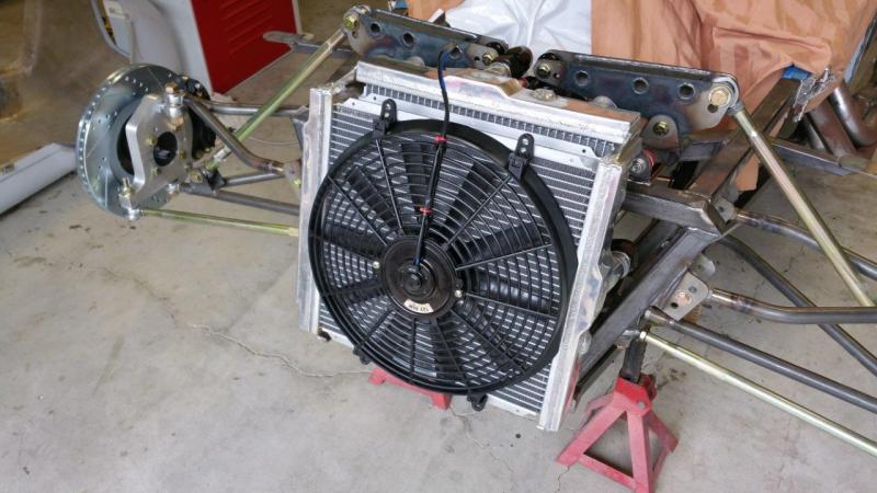
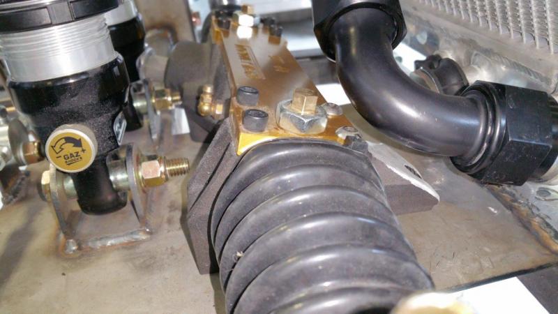
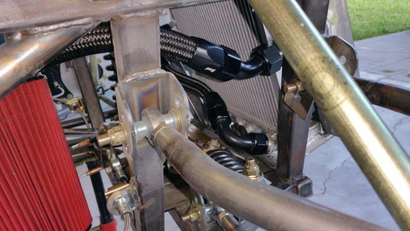
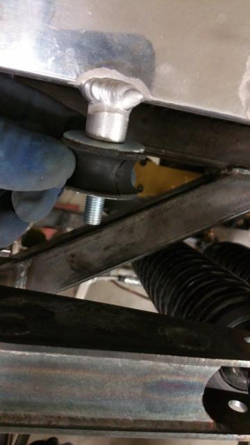
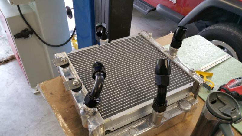
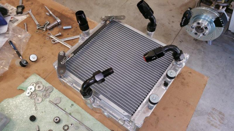
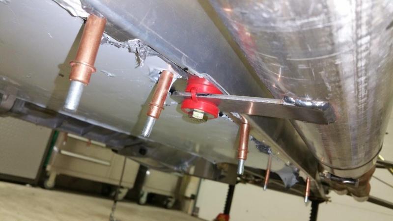
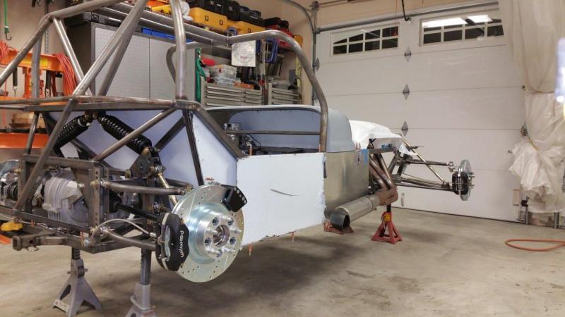
Mounted the radiator. This took a little head scratching and fabrication, but I wanted the radiator isolated from the frame. I used the same snapper grommets for the top that I used on the exhaust. I had two left. I used the bobbins for the bottom that I was also considering for the exhaust but did not use. I was thinking of using 4 of the exhaust bobbins, but one broke on me so I did not trust them. This way the radiator is always captured. Even if a bobbin fails or a grommet wears out, it is not going anywhere. This will not allow it to move enough to ever hit the suspension. Even if the grommet wore out, it would hit the bolt before it could touch the suspension. I drilled and tapped the provided mounting points on the radiator to 5/16"-24. This turned out to be very solid and should stand the test of time. It did take me awhile to figure it out and fit it. There is not a whole lot of extra space in there. I also had to shave the useless bolt boss down on the front of the steering rack to clear the lower radiator fitting. I cut the tab off the lower frame that was provided for mounting, it was in the way and in the wrong place for me to use it.
-
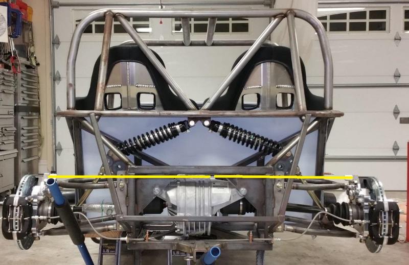
What are you guys using to isolate your radiators so they don't fail over time? I see some built with solid mounting. I do not think this is really a good idea. For one the radiator expands and contracts as it heats and cools. Also the vibration is going to transfer right into it. I see some are just putting a rubber washer between the metal. This is a little better, but is still metal to metal and vibration is going to transfer through the bolt mounted solid on both sides. I know these things might last a long time because they see so few miles, but I think I want to properly isolate mine. I am wondering what others have done to accomplish this. I am just looking into it. I might play with mounting the radiator this weekend. I just don't like fixing problems after I finish a car. I try to build them to last even if they will never see enough use for the week points to cause an issue.
-
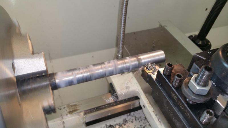
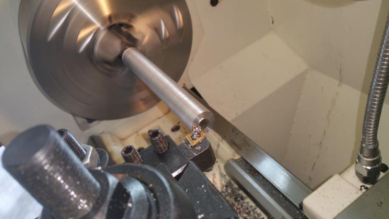
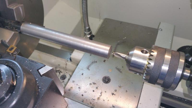
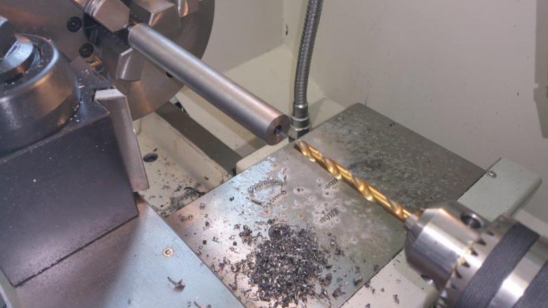
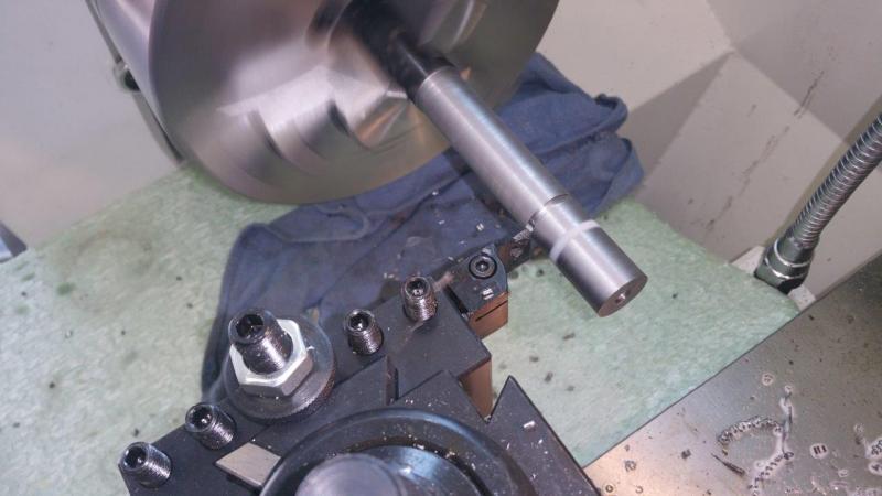
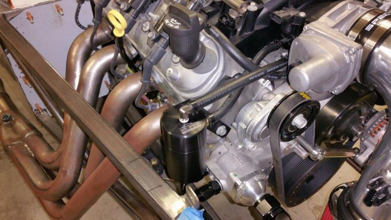
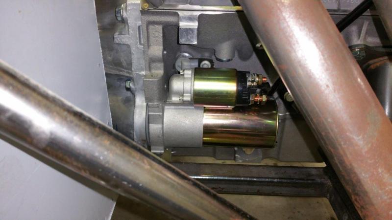
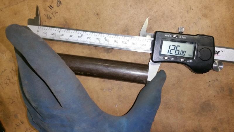
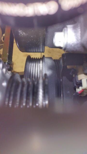
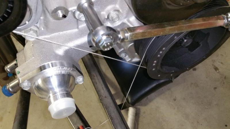
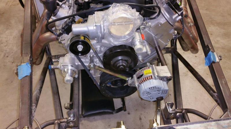
Installed the starter. Not much to say about that. Installing the alternator consumed an evening though. I did not receive the large spacer with my kit so I had to make my own and figure out how long it needed to be. This involved some string and taking it apart several times to remove material from the spacer a little at a time on the lathe. Basically you wrap the string around the tensioner, crank pulley and alternator pulley. Then you can stare down the string across the top of the crank pulley and alternator pulley. Keep trimming the spacer until the string is parallel with each side of the crank pulley grooves. The string going up to the tensioner must also line up perfectly with the string on top of the other pulleys when everything is parallel to the grooves. Lining that string up as well is critical to making sure it is all straight because it forces you to be looking at everything straight. A string just between two pulleys or trying to look at the belt for alignment is not going to be as accurate. This ended up making the large spacer 126mm. The small spacer length is not critical as long as the heim clears everything. I did however true up the edges on the small spacer. It was cut by hand or something and not truly flat on the ends. Rather than stacking a bunch of washers on the end of the large spacer bolt, I ended up cutting 12mm off the threads. This gives full engagement on the head without bottoming out and you can use one washer just so the bolt head is not grinding into the alternator when your tightening it.
-
I'm jealous! With any luck I will be back to work on mine later this week. We must have some similar tastes because I am also considering a satin black finish. Let us know how the satin does as far as showing abrasions and how easy it is to hide a touch up. Those are my only concerns vs gloss. What color are you going to paint it? I have not been able to decide on the stealth look of all black or a bright paint and all black on everything else.
-
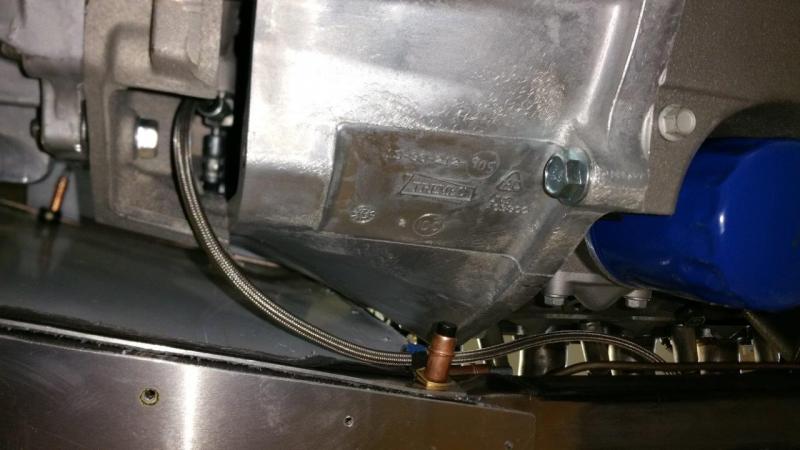
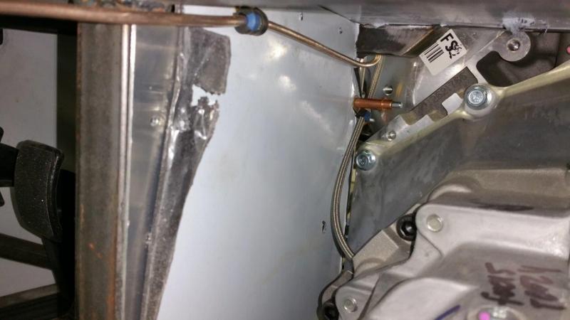
Finished up the clutch lines as well. I only needed one adel clamp for each one to keep them from rubbing or being close enough to vibrate against anything. I mounted the clutch bleeder in the same place Brunton did on the car I have pictures of. I did have to enlarge the adel clamp holes to fit it over the stud. The MS21919-WDG8 holds it perfectly snug.
-
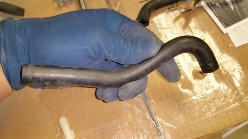
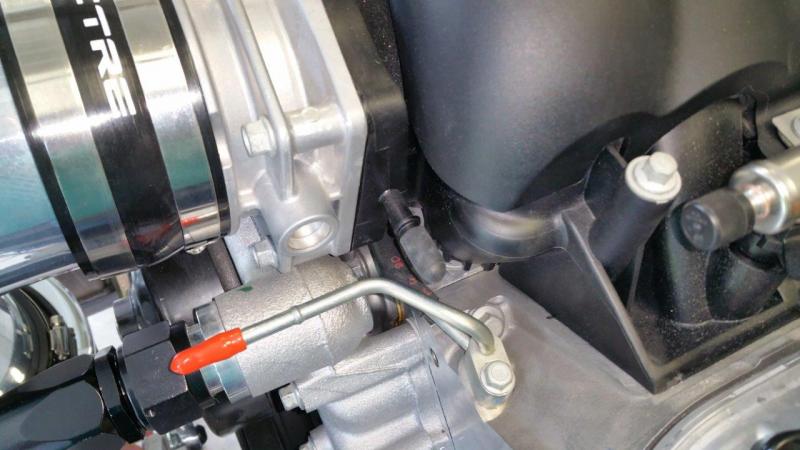
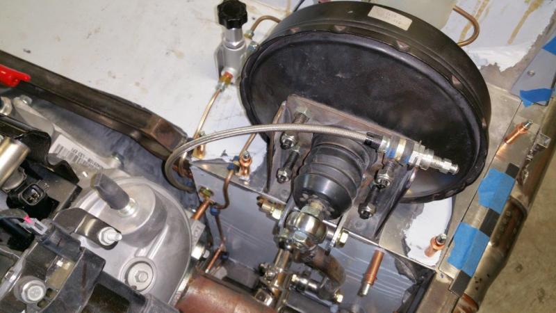
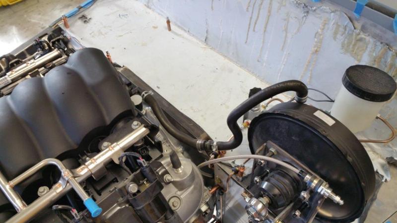
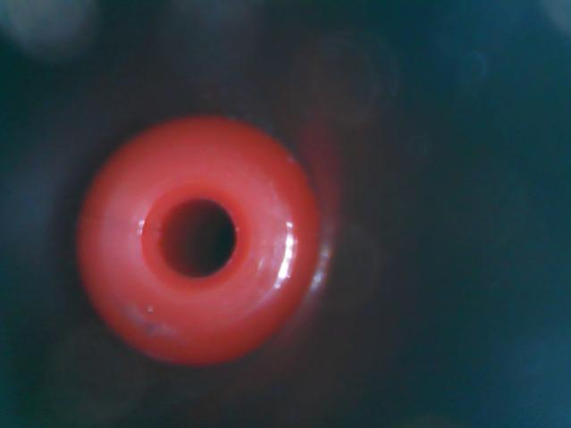
Got some smaller stuff done today. The dip stick has to be modified to clear the headers. A little has to be ground away and the paint touched up. Also, I made up the brake booster hose. I have a whole tub of hoses from various cars I have built/rebuilt over the years. I found a brake booster line that was the right size with the one way valve and restrictor in it. I could not tell for sure what the hard spot in the line was, so I got my little snake camera out to see. That red ring is the restrictor that is embedded within the hose. The other picture is the one way valve. I notice that Brunton had a plumbing shut off valve on the green car they built inline with the brake booster. I can only assume this was being used as an adjustable restrictor. I do not see a check valve though. Hopefully the check valve and restrictor in my line will work out well. I can always remove it or replace it with a different size if needed.
-
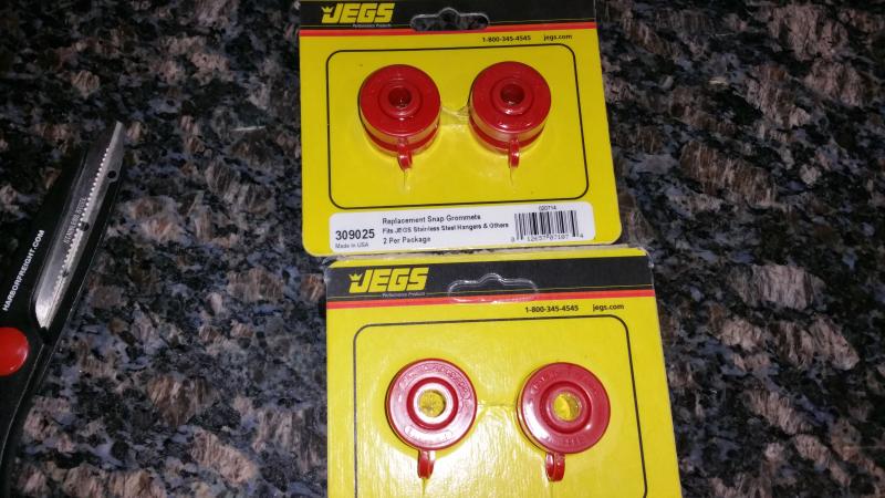
The grommets are called Snapper Grommets and they are made for exhaust. Make sure you get the silicone ones. They do offer them in black rubber or something, but those don't last as long. The ones I got are from Jegs. Part number 309025 and claim to be "High-Temperature Red Silicone". You can also find them in other places. The blue ones are also supposed to be silicone also. Not sure if they are better or not, but they claim to be the "best". I think they are all made by the same place because even the jegs ones say "Snapper" on them. If I ever have the red ones wear out, I will try the blue just to see. A few sources: http://www.jegs.com/i/JEGS-Performance-Products/555/309025/10002/-1?parentProductId=1528509 http://stainlessworks.net/grommet http://www.jegs.com/i/Stainless-Works/842/EXGRO/10002/-1 https://www.welderseries.com/blog/online-store/exhaust-grommet/
-
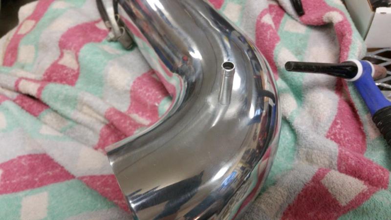
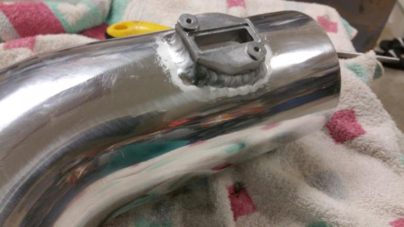
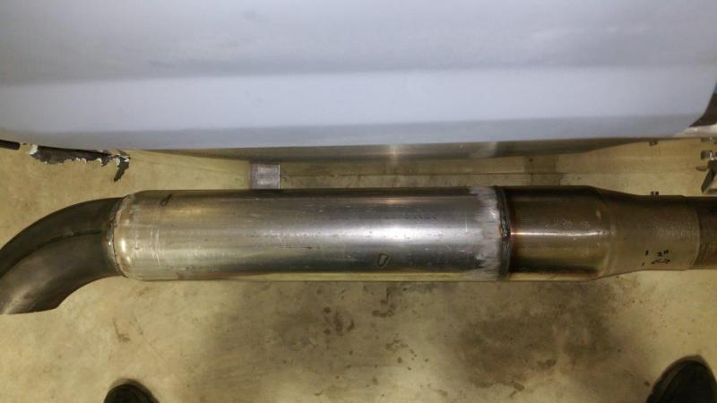
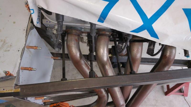
Exhaust is done.....finally. Everything is nice and straight and nothing is being pulled or in a bind! I got as much space as you could possibly get between the body panel and the exhaust. This should be reliable and simple. I do need to get a tad longer bolt. These are just shy of reaching the locking part of the nut.
-
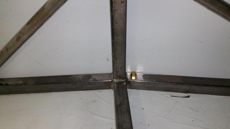
Now that I was going to use a single snapper grommet, I wanted to get as far out towards the pipe as I could. I also did not want a bolt through the floor with the head out in the way. I drilled the frame and made some spacers. Welded them in. Now the exhaust can be bolted up and everything is tucked in the frame area nice and clean.
-
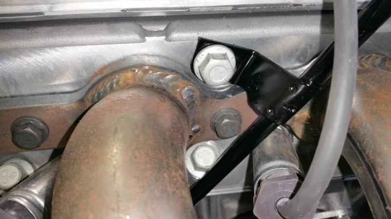
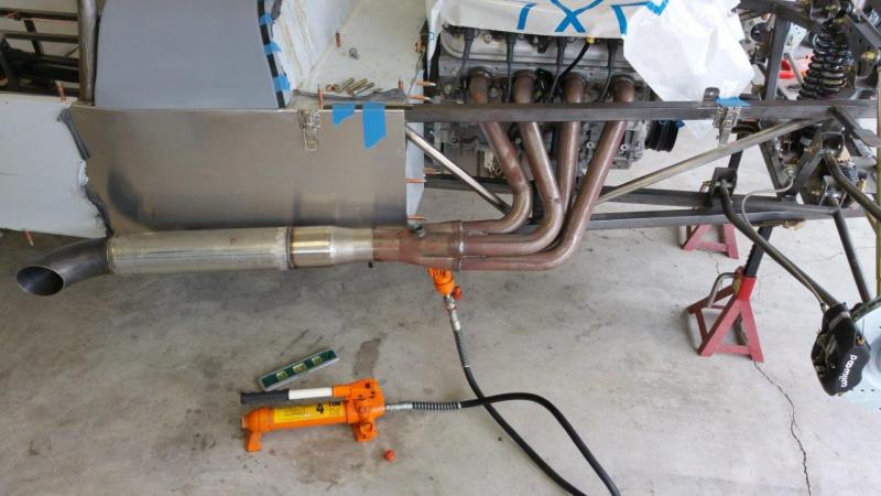
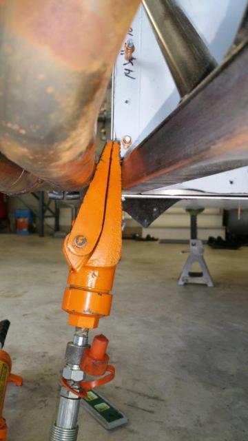
Ok, so I totally changed my mind on the exhaust and decided to go a simpler way. I was not liking some things about the way the other idea was going to work out. I needed to move it back to get the grommets farther away from the exhaust. Then I was going to have to make a new piece to weld to the exhaust, and it was getting too big and ugly. So, I went back to a more basic idea.... First, I was never happy with the difference of how close the exhaust was wanting to be pulled on the passenger side. This was part of the reason for the first exhaust idea, I could force the exhaust over a little and just have the grommets under a bit of pressure. Instead I decided to get out the portapower and make some "adjustments" I was able to pull the passenger side and drivers side and get the pipes right where I wanted them. The passenger side needed the most. This allows me to use a single grommet that is in a pretty relaxed position without it holding pressure on the exhaust to put it where it needs to be. I put the braces between the frame and the header to help alleviate stress on the flange and bolts. I was also very careful not to pull hard enough to move something that wasn't supposed to move.
-
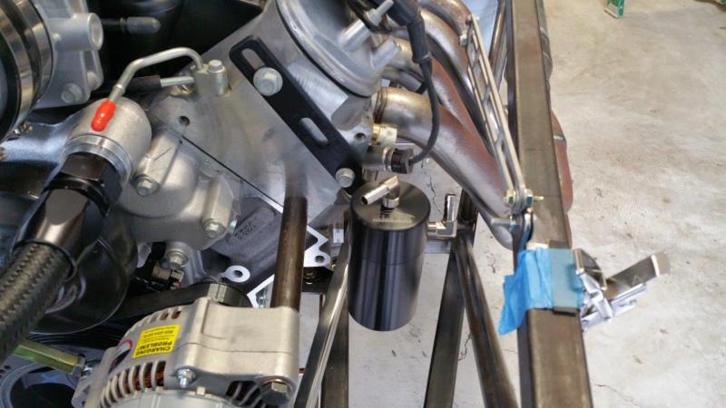
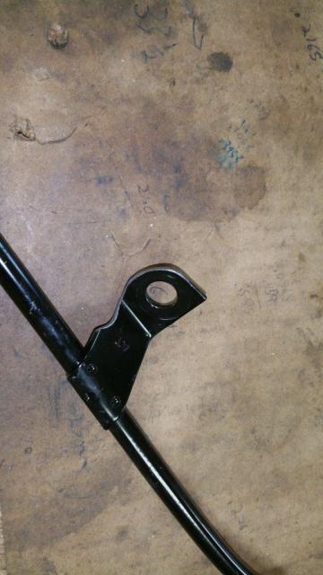
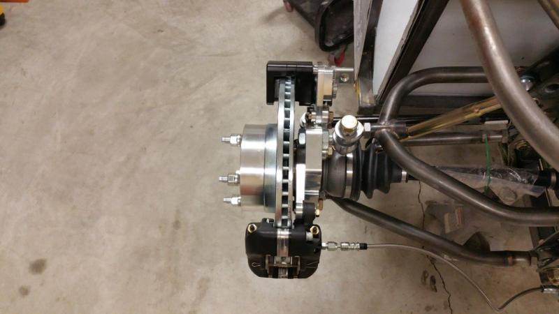
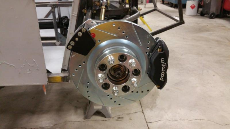
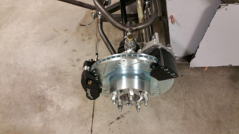
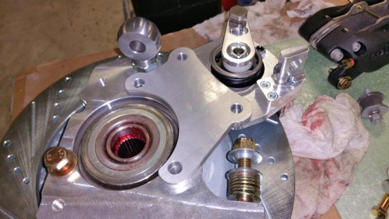
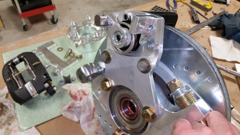
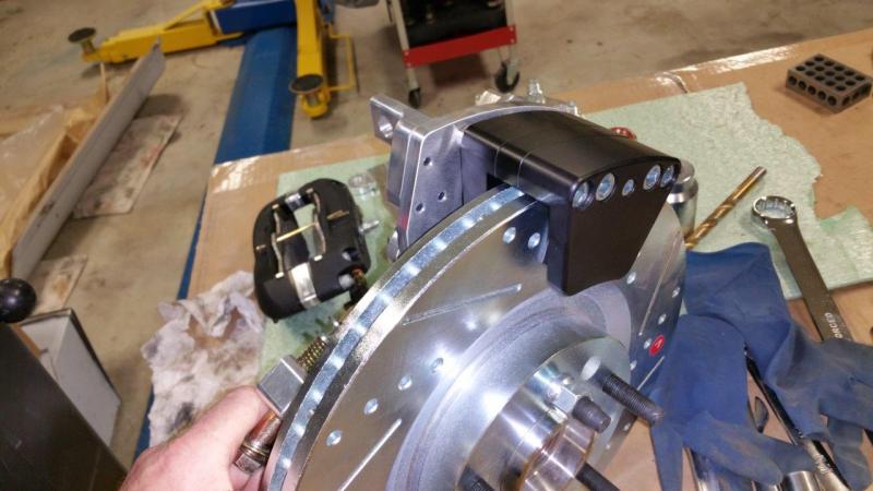
Parking brake brackets finally done. The caliper brackets from IPSCO have RH and LH carved into them. I actually have them mounted opposite right now. I am not sure why this would matter, but I am asking IPSCO just to be sure. I just think this might make it easier to route the cable. I am not set on this yet though. They can be swapped to either side and line up correctly with the rotor. I still have a lot to learn about CNC machining. I suspect I am going to end up bogging down on the exhaust bracket too. Now I am probobly going to want to make something nice and waste a gob more time EDIT: IPSCO says it is fine to mount them on either side. He said they swap them all the time depending if they need the cable to go up or down.
-
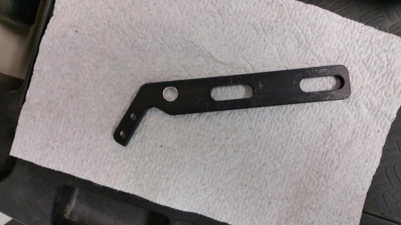
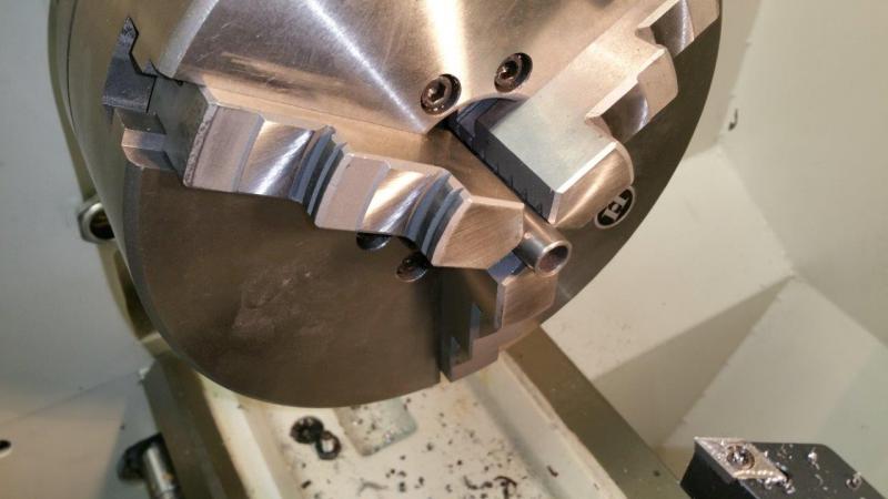
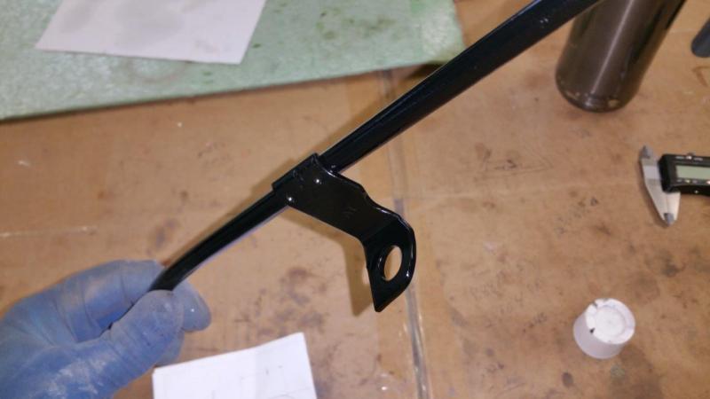
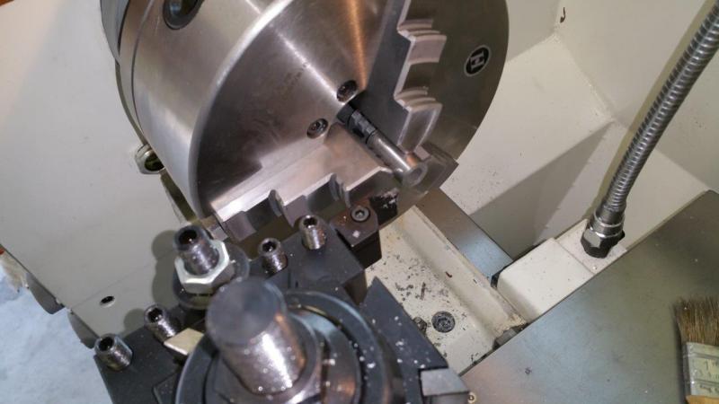
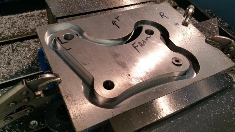
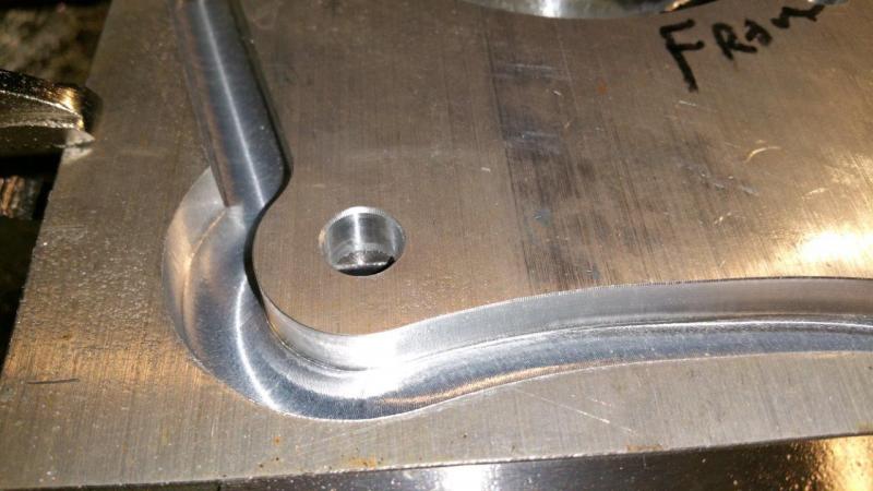
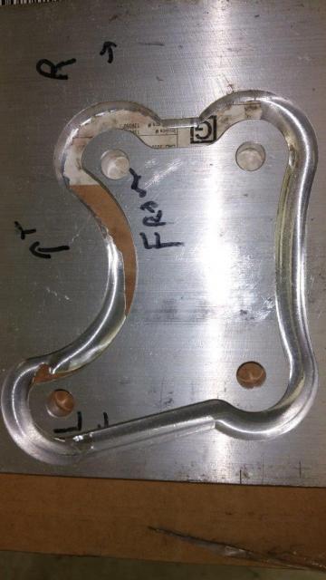
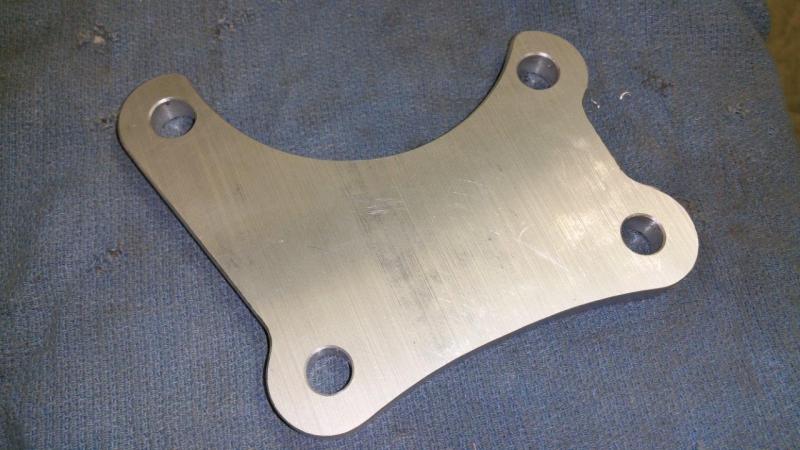
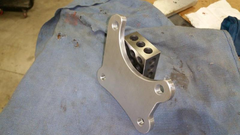
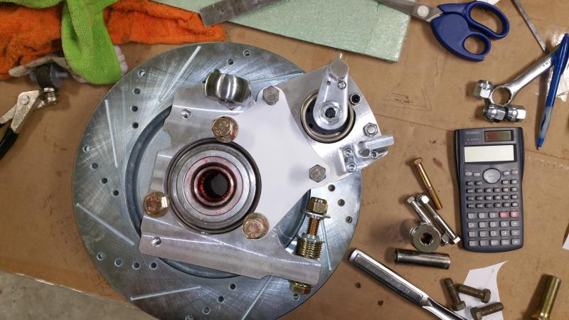
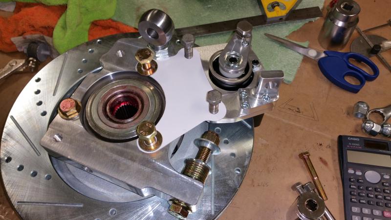
Great success! I spent the last couple weeks learning how to work CAM, create tool paths, and operate my CNC mill. Here is my finished parking brake bracket design. I need to tweak the CAM program a little to optimize the cutting operations, but overall I am very happy with my first CNC milled part. It fit perfect on the first try. I spent a lot of time figuring out what size holes for the bolts and all that for a very tight fit with zero slop. The radius of the curves and distance of the caliper from the rotor and stuff are exact to IPSCO specs. Fastenal is getting me some longer bolts for the hub bolts and new bolts for the caliper side. I just found those nasty bolts to test fit. This opens up a lot of new fabrication possibilities for me! Now I need to get this car done so I can build my next two CNC machines I have planned I designed a CNC router that I plan to build from scratch next and I need to retrofit my lathe to CNC maybe. I have all the parts and the design is done. I just need more time
-
I figured I would post a link to my resolution for this: http://www.usa7s.net/vb/showthread.php?9794-Brunton-StalkerXL-23-Build/page17
-
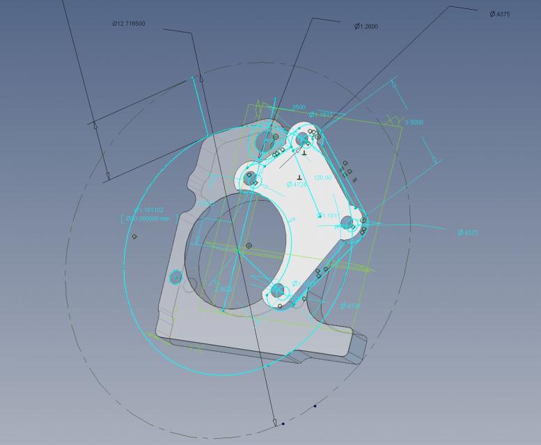
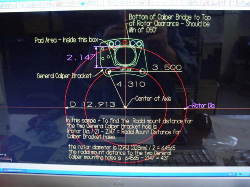
I have spent a good bit of time working on the parking brake bracket design. I think I got it done now. I just have to figure out how to fixture it up and learn how to cut on my CNC mill so I can make it. I had to reverse engineer the spindle to better figure out fitment. That took a lot of time. I plan to attach my bracket using two of the hub mounting holes. This worked out very nicely for perfect placement of the caliper on the rotor. IPSCO was nice enough to give me the dimensions needed (their picture has wrong rotor size for me, but the calcs and dims are good). I just plugged all that in as reference lines on my drawings. By the way Geomagic design is a very nice program. I have been using it for awhile. It is very similar to Solidworks, but much more affordable...if that is what you want to call it. It is still expensive for the full blown version with all the goodies. It used to be called Alibre before it was bought out by 3D Systems. It spits out nice 3D PDF's which is handy to share if you want to show a design to someone. It lets you rotate it around, zoom in and out, etc. (attached at bottom if you want look). You can even put it in different views like transparent, wireframe etc. The plan is to machine it out of 3/8" thick 6061 per IPSCO's recommendation. I also got one of my options for exhaust mounting that I am looking into. The snapper bushings actually have a little more give and are a little softer than I expected. I was expecting that they might be as hard as those polyurethane bushings, but they seem softer. This is making it harder to pick vs the rubber isolated ones I ordered. I have not received those yet. One advantage to these red ones is that even if they wear out, the exhaust is still captured by a bolt. It might be banging around, but it won't be free. If the rubber ones rip, they can become free. Spindle & Caliper Bracket.pdf