
Pokey
-
Posts
410 -
Joined
Content Type
Profiles
Forums
Store
Articles
Gallery
Events
Library
Everything posted by Pokey
-
That was the morning, the afternoon I decided to do something different and blinged it up a bit with edge trim.

-
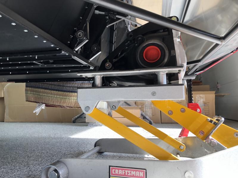
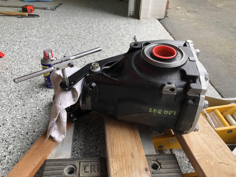
Today was rear diff day. I had read that this could be a frustrating task but for whatever reason it seemed to go okay. Having a motorcycle jack certainly helped. The only hitch was the lower mount threads were in bad shape. Bit puzzling, but rather than fight it and risk damage I dropped the diff and ran a tap through both sides. After that it went well.
-
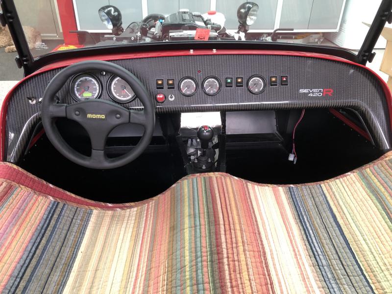
Time to attach the steering columns, and since the steering wheel has a quick release I put it on at this point too.
-
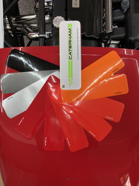
The wheel is on in the previous picture to aid in looking at colors for stripes I'm considering.
-
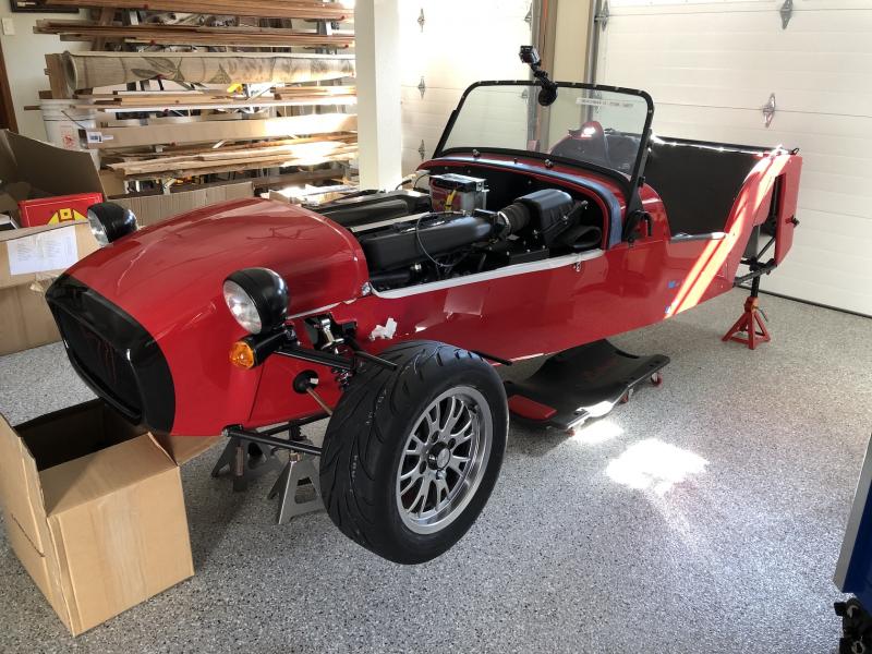
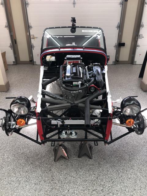
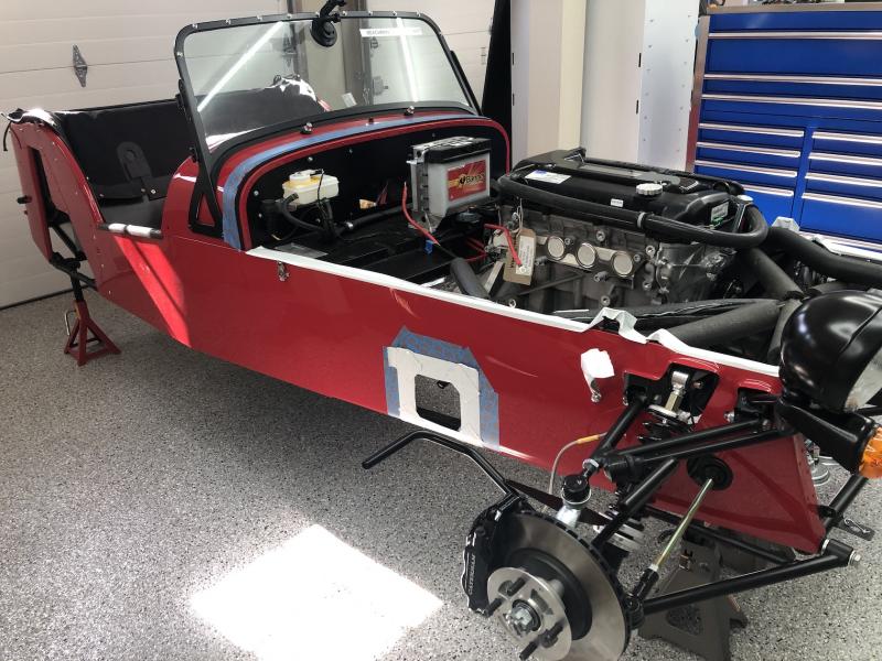
At this point it seemed like the appropriate time to put the nose cone on to see if there were any fit issues.
-
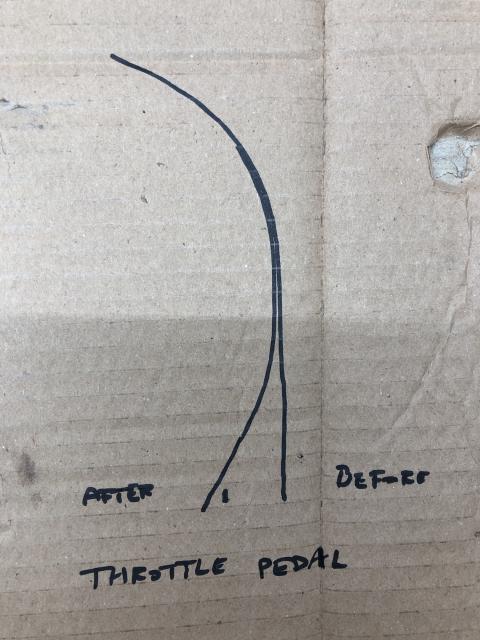
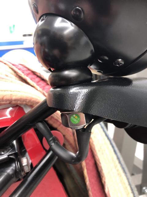
This was interesting. The throttle cable had slop, and the method to address is to bend the throttle pedal. I had to bend mine a lot as you can see in the following picture, roughly three-quarters of an inch.
-
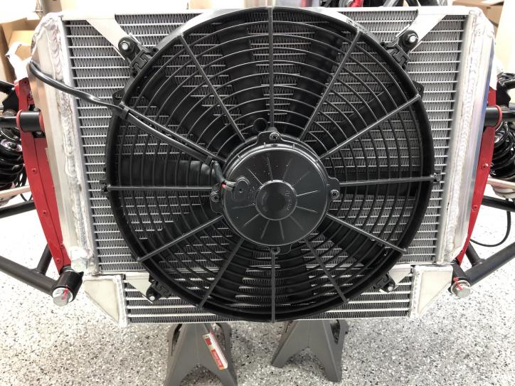
This was the only way the fan could be mounted. I was a little unsure until learning that the fan pushes instead of pulls.
-
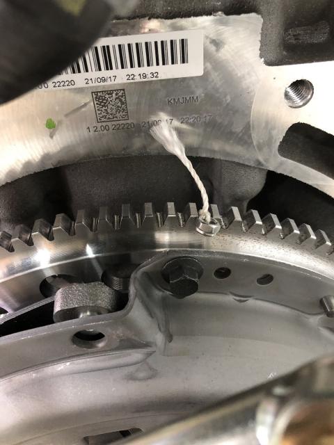
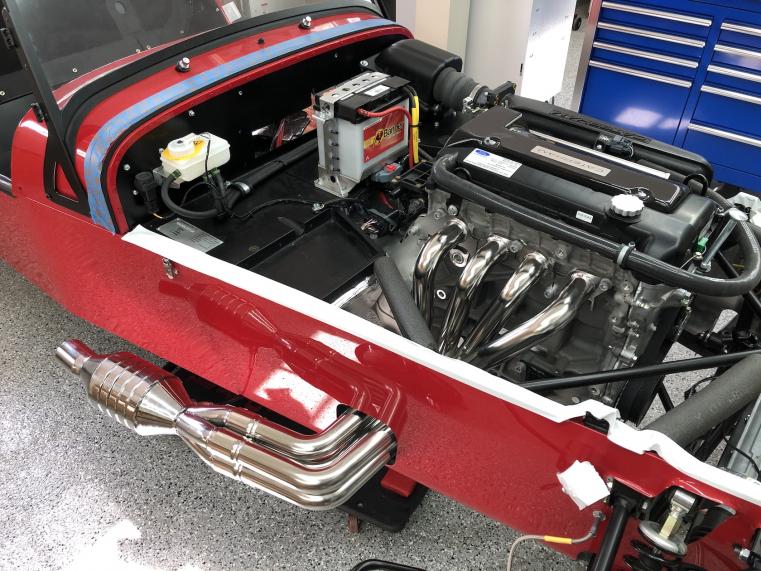
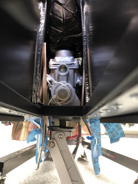
As suspected the second time was a lot easier, with the whole process of disassembly, removal, separating the transmission from the bell housing, reinstalling and reassembly taking less time than just getting the engine and transmission installed the first time around. Want to see what happened to that nut with the string attached? Yah, I'm an idiot, but I've learned to live with it. Having said that, while I truly did enjoy pulling the motor, I prefer not to repeat my mistakes so plugged that hole.
-
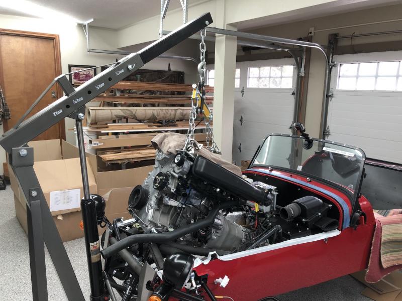
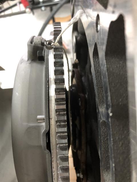
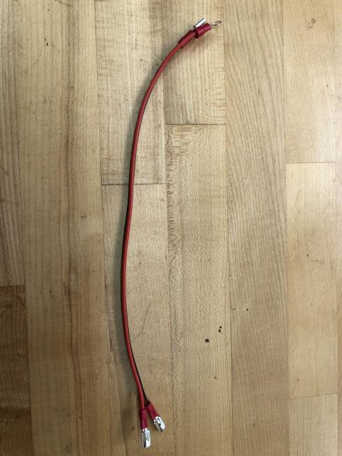
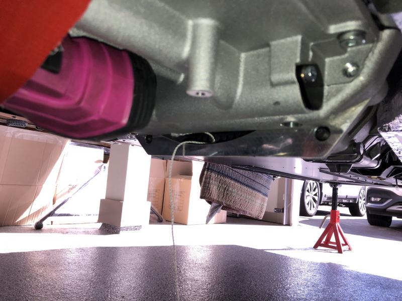
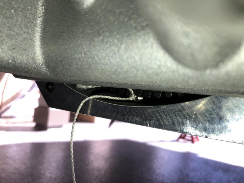
Three weeks since my last post, but not a whole lot has happened in that period. You might think that working from home would provide more time to work on the Seven, but COVID-19 is making for some long work days. Anyway, next step up was plumbing, both oil and cooling. None of the fasteners were provided to mount the oil tank and it took a few days to get the parts. Then I discovered that the return hose to the expansion bottle wasn't included, and then two of the four bolts to mount the radiator were MIA. You get the point, two steps forward, one step back, but eventually everything was assembled except the electrical connection to the coolant temperature sensor in the submarine. I didn't have small enough gauge terminals, so another online order and I was able to assemble this: Why is this significant? Well one end of that cable has a M5 ring terminal for attaching to a stud on the submarine. The submarine is located above the bell housing, or more precisely above the hole in the bell housing where the clutch hose exits. To my calloused fingertips a M5 nut is tricky little thing to handle, and sure enough I dropped it and I bet you know the rest. I figured that the nut probably fell to the bottom of the bell housing and would be accessible by simply removing the wedge that protects the flywheel. Well the nut was there alright, behind the flywheel but in plain site. All it should take is a little fishing with a magnet, right? Well that little nyloc M5 nut is about 1mm too large to fit through the gap between the bell housing and flywheel. Hmm... okay then, time to resort to my favorite wire-fishing trick using string and compressed air. I fished a string through the nut, tied it off, and then blew air into the bottom of the bell housing with the expectation (okay, hope) that the other end of the string would emerge from the hole where this whole mess started. Almost worked, about half of the string made it before getting hung up. My younger version would have spent another two hours trying to get that string to do what I wanted, but this version recognized it as a fool's errand and decided it would be fun to pull the engine. Not only would I have the opportunity to experience pulling an engine from a Seven, but I would get a chance to become more proficient at putting it in.
-
Thanks Lucky-7. The cradle is asymmetric, so can only attach to the chassis one way.
-
This thread needs a little sex!
-
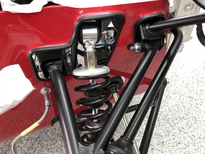
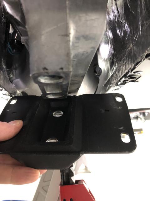
Basically you have a metal hammock suspended in rubber which in turn is inset into the mount. When installed it looks like this:
-
After disconnecting the transmission mount entirely from the chassis I was able to shift the transmission to the right. Reconnecting the mount to the chassis moves it right back to where it was before. The only way to create a gap would be to grind the holes in the mount for the bolts that connect to the transmission, and grind the transmission so that it can move in the mount as it is a cradle design (picture below). This is clearly how Caterham designed it so I'm not going to fret about it any longer. Thank you all for your suggestions.
-
Yep, mounts attached to the chassis and the bolts holding the engine to the mounts were all loosened and a crane used to take the pressure off. Even moved the crane around the front and both sides while using the load leveler to see if I could get movement. Next step is to use a floor jack to support the transmission and remove the bolts holding the transmission mount to the chassis. I want to see what happens to the alignment without the mount holding things rigid, in particular whether the transmission moves away from the point of contact on its own. I may also have contact on the left hand bottom rail as described in that Lotus7 post. I can't see a gap but it is hard to tell if it is resting on or just above the insulation tape. I also reached out to two of the guys that posted to see what they learned between then and now. One has 650 miles without issue but the other is still waiting to have his inspected for licensing so only knows what it feel like at idle. What I don't know is how experienced either are and whether they have a good point of comparison as to what it should be.
-
The engine mounts don't seem to play into this since the transmission mount is fixed with no lateral freedom. I thought perhaps I could somehow eek out a little movement so loosened all mounts, took weight off with the crane, then pried and banged a little with absolutely no movement other than that made possible by the rubber in the transmission's mount.
-
Yah, the mount for the 6-speed was (or may still be) slotted for side-to-side movement. The mount with the 5-speed that I have allows for movement front-to-back only. I need to gain a minimum of 1/8", maybe 3/16" to have any air gap. I could easily modify the mount to allow for lateral movement, but that then would presumably mean the transmission would be out of alignment with the propeller shaft. And if I make that modification there is now the possibility that the transmission might move under load banging into that spot it currently touches. The "fix" is to make the transmission smaller (grind the casing) or the chassis wider (can't see how to do that without damage). I really don't want to pull the engine to get to the transmission to grind, and I really don't want to grind, so... here I ponder.
-
Yes, the Duratec with the 5-speed (Mazda).
-
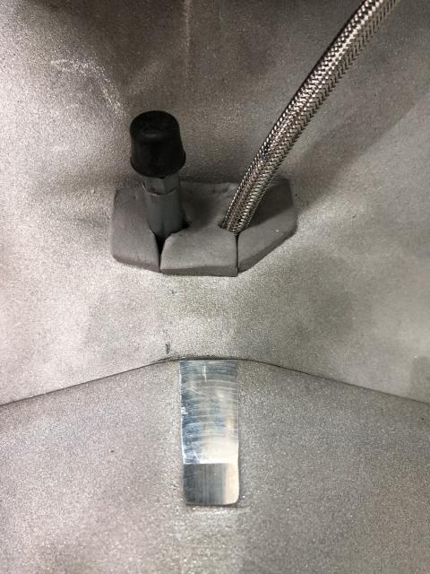
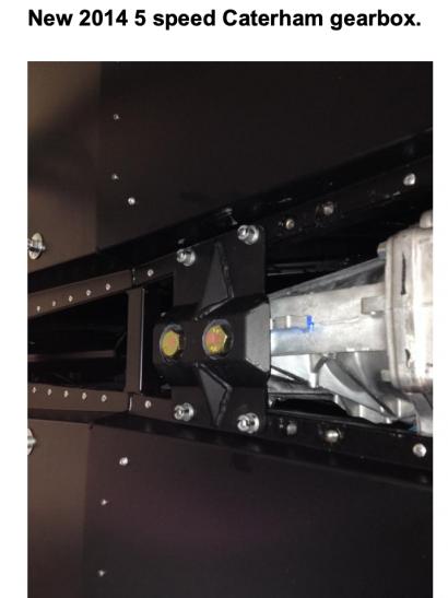
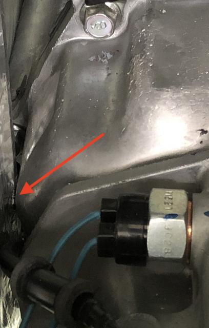
Question for you all. The transmission touches a chassis diagonal in the tunnel. I've tried everything I can think of, including loosening the motor and transmission mounts, taking the pressure off with a crane and then prying, but unless I'm putting pressure on my lever there is simply no gap. The contact area is driver side, just in front of the neutral sensor. I've found a post in Lotus7.club (https://www.lotus7.club/forum/techtalk/gearbox-7) describing the same situation with two different builds. In both cases Caterham told the builders that it wasn't an issue. Seems odd to me, anyone hear anything about this situation?
-
Thanks! I feel like I'm moving at a snail's pace, as I'm trying to relish the experience. I will say that wiggling the engine and transmission into their new home took longer than I expected though. Maybe six hours from start to end. The transmission is right up against the tunnel wall so you have to be ever so careful not to tear up the heat insulation.
-
Size 12 foot, meet size 9 shoe:
-
Victory: Sort of:
-
Thanks Kenny, I like the non-permanent nature of your solution.
-
Thanks! The only obvious spot I'm seeing to mount to is the shroud that protects the fuel filler pipe. Unless I were to build a wedge-shaped shim the bottle will be tilted on its back a little though...
-
Certainly made me feel better
-
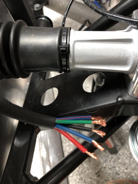
Would someone mind posting a picture of their washer bottle? The manual states that the bottle needs to be installed prior to the engine, but it looks to me like the tubing and electrical terminate in the boot not the engine compartment. However, I don't see any mount point for the bottle in the boot.