
EdWills
-
Posts
275 -
Joined
Content Type
Profiles
Forums
Store
Articles
Gallery
Events
Library
Everything posted by EdWills
-
Hi Lotus Repair. The part number, as you have found, is listed for the Series IV rear suspension small 'A' arm (page II, part no.12). It is described as a 'half bush'. Unfortunately, Redline, many years ago, while under the original ownership, dropped using all of the Lotus part numbers in favour of a photo, an old identical part, or a good description of the part. Caterham on their parts page (just enter 'bushes' in the search box), show some smaller bushes that may do, or contact Arch Motors, as they sometimes sell replacement parts with bushes installed, so probably have some bushes in their spares boxes. Good luck. Will
-
Hi Scott. I apologize if I am reading this incorrectly, but it appears that you may be referring to the alloy (aluminum) bodywork, and sorry if I am getting this wrong, but you cannot nickel bronze this material. It has to be welded with similar aluminum rod. Arch do it (according to the various pics in Lotus Seven books) by joining the alloy at the top by the damper/shock tower, and Tig welding the material together on the outside of the frame, then carefully grinding it down to make it smooth. My knowledge of frame construction engineered by Caterham is iffy. The new owners of Caterham some years ago, stopped using Arch to construct the chassis and instead turned it over to a company called 'Cages'. Cages turned to Mig welding to construct the chassis (there is/was a Youtube video by Caterham showing the construction stages of their newer version of the 7). I do not know of course if your chassis was made this way, or before by Arch? I took a couple of revision welding courses before I even attempted to touch my chassis to attach some brackets that Arch had for some unknown reason omitted. The instructor allowed me to just practice nickel bronze braze welding instead of arc welding - which I wasn't really interested in. I do have a gas fluxer, but these are now very expensive, and the flux is likewise. I would not call myself a competent braze welder, but my nickel bronze brazed joints don't look too messy. Practice a lot on scrap tubes, but make sure that they are very clean, and get all the oil or grease off using MEK. You can use already fluxed rods (try Allstate), but my instructor told me that you can scrape off some of the flux, as they plaster it on, and not all of it is required thus making clean up easier. I can send you the article, but maybe a competent local welder who is familiar with braze/bronze welding could do the job for you. I would certainly take my chassis to a local shop where a gent around my age - with tons of experience in braze welding - could do the job for me, but I already had the equipment from long ago, and I save money doing it myself without having to lug the chassis back and forth every time (I don't own a truck). Let me know if you meant something different re the chassis and body joining methods. Will
-
Hi Scott. I was under the impression that your Caterham body was still in one piece, but I see from your pics that you have at least one non-welded join in the bodywork. I also should have clarified that the 'original' Series 2 and 3 chassis did not have extra triangulation that Caterham/Arch later added in the rear of the car to add some strength. They also riveted some extra paneling to the bracing (just behind the seat back) that would require rivet removal and 'uncurling' .. I do not know how much extra triangulation, and therefore riveted body panel(s) your chassis has. I see that you were just asking for the benefit of future readers, but of course there have been many chassis variations over the years, and perhaps removing a body in one piece may not be practical? I also removed a set of body panels from a Caterham/Arch chassis, and it was much easier to cut the panels either side at the weld just below the bracket that holds the hood sticks (by the shock tower). A tad easier to hide this join if you do not intend to have it welded back as it was in the first place. Will
-
Hi Scott. I was able to accomplish this on my original Lotus Seven Series 3 many years ago when the car suffered damage after I was forced to drive over a very raised up manhole cover (I was boxed in, and unfortunately too late to see it!). The bottom floor skin, among other items on the car, was badly damaged (torn), but the chassis was not bent. I stripped the car completely, turned the bare chassis upside down, and drilled out all of the rivets on the bottom of the chassis. I then turned it right way up, and removed the rest of the rivets from the panels. I was able to carefully pry up the side panels starting at the bottom, along with the rear panel by gently uncurling it starting at the bottom. With help, I was then able to peal the complete body - consisting of both sides and rear still attached - by lifting it upwards from the tubular chassis. I braced the entire body work using 1" x 2" pieces of wood (using screws in the rivet holes) to completely brace the structure so that it would not buckle or crease whenever I moved it. I was able to drill 1/2 inch dia. holes at the very front of the top and bottom 1 inch square side tubes to release most of the drilled out rivets from the chassis. I lifted the chassis up high at the rear and shook it from side to side a bit to release most of the rivets trapped inside the tubes. Arch and Universal Radiator did not tend to block off any of the main tubes when constructing their chassis. A vacuum cleaner also helped suck out any loose debris and the rest of the rivets. The holes drilled at the front to release the drilled out rivets can be (braze or fusion) welded closed when rebuilding. To replace the bodywork when all of the repairs have been completed, Cleco skin pins are ideal for 5/32" holes. If you drill a rivet out and the hole becomes too large, you may have to go to a 3/16" rivet for replacement. When drilling out 5/32 inch dia. rivets, use a slightly smaller drill bit than 5/32 if possible, by using a numbered drill bit. This may help prevent the rivet hole from becoming larger than 5/32 inches. It seems that Monel replacement rivets in 3 lengths may be harder to obtain these days. Try Hanson Rivet in the U.S. or Rivetwise in the U.K. Hope this helps if you are still considering removing the ally body completely. Good luck. Will
-
Replacing the bushings on a Lotus Seven Series 3 front suspension.
EdWills replied to EdWills's topic in General Tech
Hi. Unfortunately, a typing error occurred regarding the measurement of the complete bushing kit assembly installed on the trunnion. It should have read 1.578 inches.My apologies. Will. -
I decided to replace the nylon bushes, dished washers and spacing tubes in the trunnions on my Lotus Seven Series 3 lower front suspension. I had a spare service kit from Rimmer Bros, and followed the diagram included in with the kit. I assembled the unit as shown in the diagram, but it would not fit in between the lugs of my lower 'A' arm/wishbone. The measurement was reading as 1.78 inches total width with the trunnion and assembled kit on my digital caliper. The inside measurement between the outermost lugs on the wishbone should be 1.5 inches according to a diagram kindly posted on the web, and also as per my wishbone (Arch/Caterham manufactured, and fusion welded, not braze welded, as my Lotus originals were. Note: Braze welded suspension components are illegal in my Province in Canada, and possibly others. My Lotus braze welded originals had been 'butchered' by the second owner to attach lugs for towing the car in case of breakdown at the race track). I checked my Standard Triumph Spitfire Mk.1 and Mk.2 parts book, and way back when these were manufactured alongside the Triumph Herald that Lotus used parts from for the front suspension on the Series 2 and 3 (and very early Caterham 7s), the outside cupped spacer/washer was never used. Tony Weale in his book 'Lotus Seven' also shows that the outermost cupped washer was not used. On very early Triumph Herald cars, the cupped washers (inside and outside) were not an included part as shown in a very early Triumph Herald manual that I also have. It would seem that the outer cupped washer was for addition to later Spitfires, Vitesses etc., to perhaps better protect the square section rubber ring placed onto the nylon bush. The Series 4 had 2-part wishbones (on both upper and lower) so fitting the entire kit is not a problem. The only way to fit the 'newest' kit with the 4 cupped washers, the nylon bushes, and the spacing tubes, would be to open up the space between the lugs on your lower wishbone. These are heavy gauge steel, and some bending force would be required. If you do it wrong, the bolt may not fit correctly. It's not very much to open up the gap, but you takes your chance as they say, and it isn't original..... So, if you need to replace the trunnion bushing set-up, just leave off the outer cupped washer, and it should fit nicely. Cheers Will. Lot7Susp.pdf

-
This site (below) may be the same source as the assembly manual alluded to by 'Croc'. Apologies if this is duplication on my part. W.
-
Someone going by the name of 'Barnblinker' http://barnblinker.com has very kindly taken the time to download the entire Lotus Seven Series IV parts and service manual on to his site. The Lotus Seven parts manual by Caterham covers the Series 2, Series 3, and Series 4, if you can find a copy. Will
-
Redline Components U.K. has the chassis mounted rubber bush part number 046D 6000 in stock for just over 43.00 Pounds Sterling (each), if this is the part that MV8 was referring to above? This is/was possibly a front or rear bumper mounting rubber used on a different make and model of car, or possibly on another Lotus as an engine mounting rubber insulator. Will
-
A good source of information regarding the Lotus Seven Series IV is a gent in Germany by the name of Hajo Steffen. He has produced a couple of Youtube videos, and runs the German Series 4/IV club. I do not have his current contact details, but he can be contacted via Youtube or Facebook? He can advise on parts availability as well as history on the Series IV as necessary. Will
-
Hi Chris. Please see the post to your other entry on this forum. Will
-
Hi Chris. Dennis Ortenburger in his book 'Legend of the Lotus Seven' on pages 106 and 107 provides information on the Super 907 twin cam, and the deal between Lotus and Steel Brothers, heavy equipment manufacturers in Christchurch, New Zealand. I would try and copy the information to add here, but the book is new and doesn't fit very well in my printer. Steel Brothers only manufactured the cars until 1979 according to Ortenburger, as new safety regulations came in force in New Zealand at that time, and the 907 could not meet the standards. I contacted Steelbro in 2002, and a Mr. Alistair Coleman of Steelbro confirmed that his company sold the jigs, but understood that they had been sold on again to Club Lotus New Zealand, based in Auckland. He provided a contact phone number for Warwick Chandler in Auckland. Murray Osbourn of Club Lotus confirmed that they were attempting to keep the Series 4 going by providing parts and chassis for owners of the Series IV.. We are talking here about the early 2000s, so I do not know if this still holds true. As Steelbro were manufacturing the 'original' Series IV alongside Arch and Griston Engineering, parts should be interchangeable, except probably for the 907, as the chassis was stiffened to the tune of 20 lbs. of extra metal tubing, and widened. If the rear suspension links that you are wanting to repair weren't altered from the original IV jigs, Arch should still have the capability to either repair or fabricate new ones (preferably with bushes in place?). I have a very brief story of the Series 4 or IV if preferred, at anglocanadianlotus7.ca provided by the mechanic who worked on the Lotus production line. Tony Weale in his book also provides excellent details on the Series IV. hope this helps. Will.
-
Hi JB. My 1969 Lotus Seven Series 3, purchased from a great gent in Edmonton (I'm the third owner), had the 116E gearbox with close ratio gears and the pre-uprated 1600 c.c. Crossflow engine - 681F and 2737E block connected by a 105E bell housing and 7 1/2 inch clutch. The car had been fully built at Lotus and exported to the concessionaires just outside of Toronto (a number of fully completed Series 3 Sevens entered Canada this way, and as you probably know, a number arrived in Edmonton at Anglo Canadian Motors).. My car is L.H.D. The 116E was also fitted to the pre-crossflow Mk1 Cortina and the Lotus Cortina according to Paul Davies in his book on four cylinder Fords.. The early 105E and 109E boxes fitted in Ford vehicles only had synchromesh on the top 3 gears. After 1967, all boxes came with synchro on all 4 gears. My gearbox had the rubber mount that you show at the top in the first photo. It seems that the gearbox output shaft housing was available in 2 types to take either of the insulating rubber mounts as shown in the additional great photos from other forum contributors. The gearbox mounting cradle, as you and others note, was riveted in the tunnel. The hole for the rubber insulator mount in my cradle had become very large (the car was actively auto slalomed and raced by the second owner). Unfortunately, he didn't always check the tightness of all the major engine and suspension bolts! I purchased a new bracket from Caterham in 1970, and they had drilled a slotted hole to allow for side-to-side adjustment of the gearbox. When supplies of the 116E ran out, Lotus started using the 2821E box (incorrectly known as the 2000E). Near the end of the run of Series 3 cars (1970), the 2821E may have been substituted for the 116E. I have a complete build story from Cars and Car Conversions (July and August 1969), where one of the magazine's staff built a Series 3 for the magazine. It was fitted with the 2821E box. The Series 4 (1970 onwards) likewise was fitted with the 2821E, and when used with the twin-cam engine, the twink clutch at 8 inches diameter., and the twink bell housing, a special metal adapter had to be added extending the clutch release bearing to allow the clutch to operate correctly. Tony Weale details the part number in his book. The later rubber insulator as you show below your original, was used for the 2821E and the 116E according to diagrams in the Autopress Ltd., Ford Cortina 1967-68 Autobook by Philip H. Smith (U.K.), depending on the output shaft housing used. Caterham/Arch produced the reinforced metal bracket with triangular sides to fit in the tunnel area which was welded to the chassis. It incorporated a welded bottom rectangular tube to allow the rubber mount to be bolted to. Weale advises that the 116E was used on the Seven from 1962 to 1971, and the 2821E from 1966 to 1970. He does indicate that the latter box was used by Caterham up to 1980. Cheers, Will
-
Previous posters have requested information regarding Mick Beveridge of Xtra Special Sevens. I have personally purchased a number of items for my Seven from Mick, and in our last correspondence some time ago, Mick told me that he had not been very well. He is a great guy, a Seven specialist, and an excellent fabricator. Knowing that Tony Ingram of Fast7s has imported some of Mick's parts, I contacted Tony. He advised that 'I know that Mick had lost his workshops and that stopped him from doing any business'. Tony added that there was no contact from Mick anymore... I tried the only telephone number I have for Mick, and got an answering machine from another company now using Mick's number. As I, and others have found, there is no reply from the email address that Mick was using. A month ago I emailed him - just to find out if he was o.k. - but no reply. I sincerely hope that he is o.k., and it is a sad day for him and us if he had to fold up the company. Cheers W.
- 1 reply
-
- 2
-

-

-
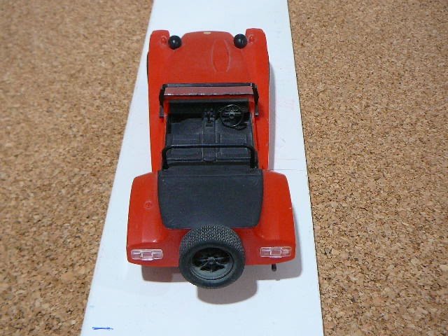
Hi Scott. Thank you for the picture. The poor(er)? relative of the Series 2 and 3 seems to have been left out of the plastic model kit world except for the model I have. I was pleasantly surprised when I found it. I was on holiday visiting relatives over the pond and took time to visit Brands Hatch racing circuit with my wife. I got to see one of the (four?) versions of 'Black Brick' in a club race. Owned by Rob Cox Allison, a very friendly/very likeable race car driver, who was perfectly happy to tell me all about his car as he worked on it in the outfield paddock area . Also racing was a standard Series 3 Seven owned and raced by Maynard Soares who won his class (rag top fitted, and when racing, looked like an inflated balloon). I would have liked to see the Lotus 7X racing. I was living in the U.K. at the time that Tim Goss was so successful with the car, but unfortunately had other commitments. I had attended Brands Hatch on Boxing Day a year before, and nearly froze to death. How they raced in such frigid conditions I will never know. Also very icy under some of the bridges. Cheers. Will
-
Apologies. This was sent off before I could load photos. EW
-
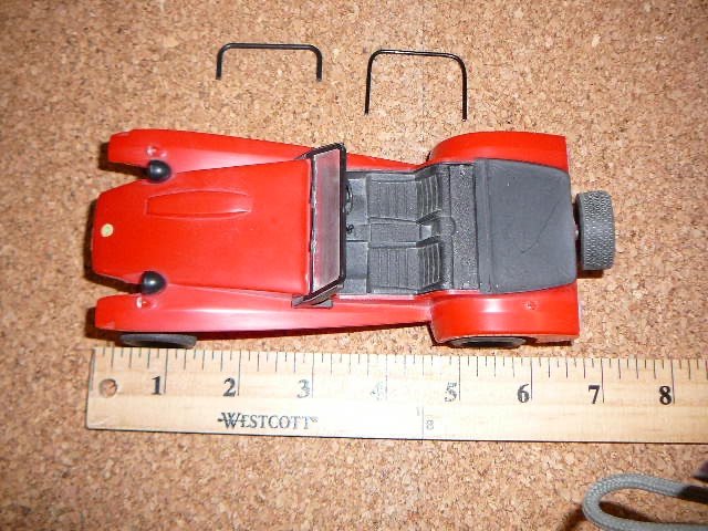
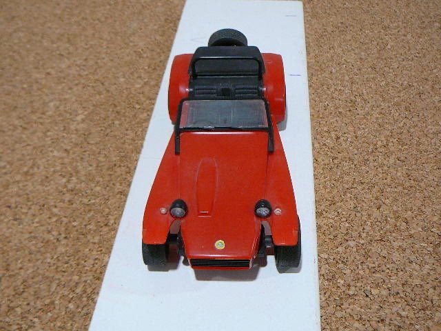
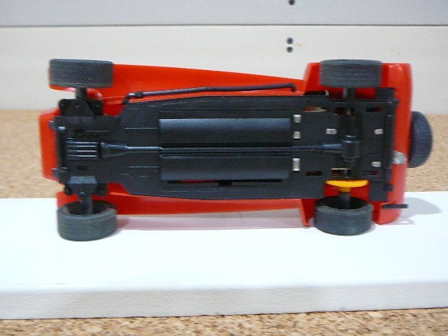
For Sale: 1/20 scale plastic model kit by Nichimo, Japan, of a Lotus Super Seven Series 4. It is mostly assembled, but the roll bar has not been attached in case of breakage. There is no damage on the model. A spare formed black metal wire roll bar is also included. There are not many separate parts to this model, so it came mostly assembled. To split the body from the chassis requires gentle prying at the bottom of the nose cone to release 2 small plastic clips. It can then be repainted if necessary to a colour of your choice. The headlamps, exhaust and windscreen can be removed if necessary for painting or masked off. The model is motorized, and requires 2 'AA' batteries, (but not included as the weight of these drives up the postage cost into the next price bracket!). The model was purchased in 1983 from a stall at Brands Hatch U.K., and sat on a shelf since then. The front wheels of the model have steering capability. I have found a couple of unmade boxed kits on line on e---, but they are very expensive as the kit has not been produced for a long time.. Offers in the region of $75.00 plus postage (tracked and insured).
-
Hi Terry. A number of years ago I required new brake piston seals for my 1969 Lotus Seven which is equipped with the later 14LF callipers from the Mk3 and 4 Spitfire (This information is according to Goodridge U.K.) Girling U.K. has a web site contact option, and may be best to contact as they can go back into their library and advise which seal kit is best for your situation. Goodridge U.K. were also very helpful, and supplied me with a photocopy of all the parts for my callipers. They mostly sell brake hose kits for many U.K. and European cars and did include the Seven, but I couldn't find the Seven kit on their site anymore. Burton U.K. were also very helpful with brake line kits and I obtained a 'vintage looking' set for my Seven from them. You probably know this already, but it is best that you do not attempt to split the calliper bodies undoing the bolts. A new small rubber seal would be required (this can be obtained still as a spare part), but leaks may ensue if the halves are not bolted back together with the correct torque. Lotus and Girling recommended that you should never separate the halves. Good luck with your search and kit experience. EW
-
I should clarify my statement regarding Haynes's valve size specifications for the Ford Escort Mexico in their manual. They are correct depending on the date of manufacture of the cars they were featuring. According to David Vizard in his handbook "Tuning Escorts and Capris", for Crossflow engines fitted up to August 1970, the valve sizes for the standard 1100 and 1300 were 1.41" diameter for the inlet, and 1.25" for the exhaust. The 1300 GT engine had inlets of 1.5", and 1.25" for the exhaust. The 1600 and 1600 GT engine had the same size valves as the 1300 GT. After August 1970, Ford started using the uprated engine, and the valve sizes increased to 1.55" for the inlet and 1.34" for the exhaust on the 1600 and 1600 GT. This was when the flat head was used replacing the head with the slight recess and the bowl in piston with no valve cut-outs. The uprated head required the pistons to have valve reliefs machined in the tops of the pistons. David Vizard advised that the best head for modification was the 1100 c.c. flat head casting. It had much more metal for enlarging the ports, as well as allowing for larger valves. Way back, I purchased at auction a 711M oil pump engine originally from an oil company for $25.00, and the head was fitted with the flat head 1100 c.c. casting with small valves. On a trip over the pond, I took it to Oselli Engineering in Oxford, and they installed hardened valve seats on the exhaust for unleaded fuel, bronze valve guides, and valves of 1.6" inlet, and 1.34" exhaust. They called this stage 2+. Note: 1.6 m.m. is considered the minimum space between valve edges to prevent cracking of the metal between the valves under hard driving including racing conditions. In my case, I have a space of 1.725 m.m. between the inlet and exhaust valves on my cylinder head. (There is a formula for this if interested?) Cheers, Bill
-
Hey Scott. According to the sales blurb for the 1970 introduced Ford Escort Mexico, the engine was a more economical power plant than the one used for the London to Mexico Rally.. The Haynes Manual for the Ford Escort RS1600 and the Mexico 1600, notes that the valve sizes for the Road Escort Mexico are the same size as the 1600 Crossflow pre-uprated engine used in the 1600 Cortina GT and Lotus Seven Series 3.. Seeing as the uprated 711M engine with slightly larger valves was introduced by Ford at this time (used in the Lotus Seven Series 4 and later Formula Fords), fitted with the flat head and stronger block with meatier mains caps, it is possible that Haynes were publishing older specifications for the pre-uprated engine in their Mexico specs. "A good example of a powerful but flexible use of a push-rod engine is given by the units used in the Works Escorts on the 1970 World Cup Rally. These engines were taken out to 1830 c.c. by boring and fitting a specially made long throw crankshaft. The flat cylinder head, with very little work done to it, retained standard valves but compression ratio was upped slightly to 9.5:1 by fitting Mahle pistons. Twin 45 DCOE Webers with 36 m.m. chokes were used and the camshaft was the Holbay R120 (my note: as used in the Lotus Holbay 7S Seven and available for the Series 4 as an extra). Power from this set up was approximately 140 bhp at little over the normal rpm figure. These engines were built with reliability in mind as much as power - and they proved successful, as everyone knows." Quote from "Tuning Four Cylinder Fords by Paul Davies" - published by Cars and Car Conversions Speed Sport Motobooks. So, I'm guessing that someone - perhaps other than Ford - has machined your head to take the maximum size of valves available. You may have to check that the area between the valves has sufficient metal as one tuning website notes that cracks can occur when the head is machined with the valve heads too close together. If I can find this site, I will pass it on to you if you are interested. Cheers, Bill
-
Hi Scott. In the article it shows the rear axle of James Whiting's car. No noticeable reinforcing plate to strengthen and prevent twisting to the axle and no special suspension set-up - just the regular rear 'A' frame. With the maximum 160 bhp on tap from the 1650 c.c. twin cam, and using the car for sprints and drag races, I guess the Ford axle can and did take the punishment without falling apart? James Whiting has another lightweight Series 2 Seven that he rebuilt with lots of alloy parts including gearbox, bell housing, and diff. carrier on it. Being an ex Rolls Royce mechanic, he has enough experience with cars to know what will and will not work. He has an extensive Seven restoration and repair business. I purchased a few sets of spark plugs with different heat ranges from him, and he was very helpful with advice. The magazine also featured Burton Performance in the U.K., who are excellent for Ford parts. Still going strong after many years in business with the same family in charge. Again, very knowledgable and v. helpful. Cheers Bill.
-
Hey Scott. Many thanks for posting this. I found the mag. at my Local Indigo/Chapters Store in Canada, and if anyone needs a copy they have a few left. $14.99 Canadian plus postage. Lots of interesting articles along with the Caterham 7 comparisons plus a description of 2 Lotus Mark 6 cars. Plenty of other great articles too. Cheers. Bill
-
Caterham A Frames - check them as part of your annual maintenance
EdWills replied to Croc's topic in General Tech
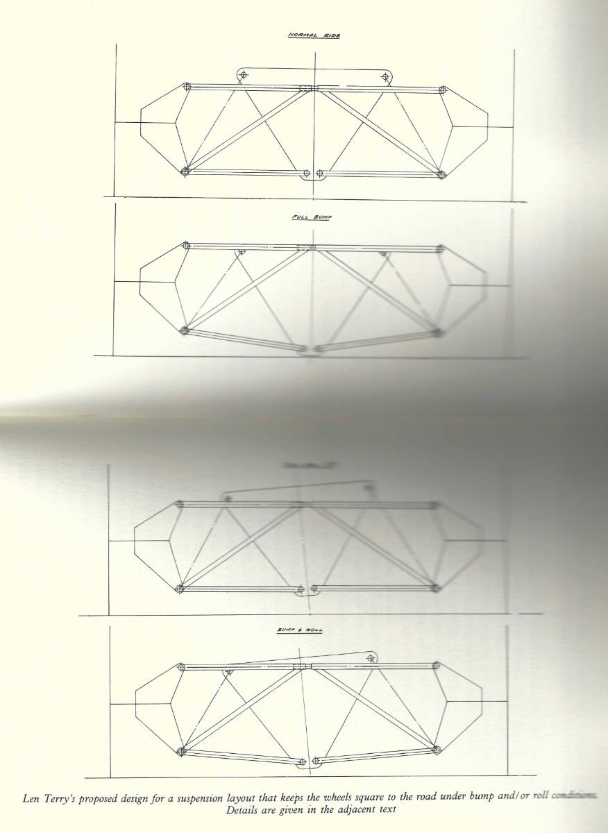
Hi MV8. Correct, the thin lines are the coil overs. Len Terry was quite a character, and I had a few emails back and forth with him before he died. Regarding the layout shown in his book, he advised the following: "It comprises two simple frames, each forming a triangle with its 'upright', connected to a sliding joint. Each frame is located by a parallel-arm lower link, as shown, and by the usual top and bottom longitudinal radius arms which are not seen in this view. In the drawings the body is depicted purely diagrammatically to indicate the attachment points. This system keeps the wheels perpendicular to the road under any combination of bump, rebound and roll, and the lateral sliding travel at the central joint is less than half an inch. Unsprung weight is clearly rather higher than for a conventional rear suspension, but the advantage of no camber change could well outweigh this, and the structure does fit surprisingly well into the layout of a normal open-wheel racing car". Apparently, Len Terry did not incorporate this design into any of his cars, or those for Lotus (too bad!). Just an aside. Way back when Lotus was going up-market, they would sell off many of their sports and racing car spare parts at the factory. They would bundle them into wooden tea chests, 2 feet x 2 feet x 2 feet or so, and you purchased the tea chests more or less items unseen, not knowing what was in the middle and bottom of the container (you were not encouraged to dump the contents out at the factory apparently!). A friend of mine purchased one of the chests from the factory, and inside were a pair of new cast alloy rear uprights, drive shafts, brake parts, wishbones and lots of other assorted bits and pieces from their Formula Ford cars and other G.P. cars. The price, according to him, was quite reasonable, and he planned on using some of them on a couple of Lotus formula cars that he owned, as well as a Seven. Best, Bill. -
Hi Scott. The Series 1 and Series IV Seven had the battery mounted in the boot. It would probably require a smaller capacity fuel tank to accommodate the battery as per the Series 1 unless you can mount a fuel tank above it as in the Series IV. In the photo above, it appears that the boot board is sitting much lower than normal for a Seven, so allowing the battery and fire extinguisher to be fitted there. With the de-Dion set-up on this particular car, there should not be a problem of the differential case hitting the underside of the lowered boot board (a definite possibility with a solid rear axle car) as in the de-Dion set-up, the diff case is bolted firmly in place. You can check SimpleSevens.org, and search the 'History' section, click on 'David Porter's 7/20' article, and at the very bottom of this section there are photographs of the bare chassis of a 7/20 look-alike race car. In one of the photos it shows the bracket for installing a battery at the rear on the opposite side from the driver. The fuel tank in the 7/20 is smaller than the regular Seven Series 2 or 3 tank. Caterham had a battery bracket manufactured by Arch for their Sevens that fitted on the passenger side of the car in front of the firewall in the lower engine bay area. Tony Weale noted that it may be difficult to service the battery in this location, and Caterham resorted to using a 'no maintenance battery'. If you check the Odyssey Battery web site, there are various sizes of dry cell batteries that may be suitable for your use. USA7s has a forum page detailing various batteries for the Seven with recommendations from owners. Cheers, Bill
-
Caterham A Frames - check them as part of your annual maintenance
EdWills replied to Croc's topic in General Tech
Hello Gents. Although this design is perhaps not very practical for a Lotus Seven due to the cost and complexity of the system, this drawing of a De-Dion rear suspension by Len Terry would have complimented his other arrangement for the rear suspension of the Lotus Type Three Seven race car. The Terry design in the attached drawing is still in the Lotus vein with the small diameter tubular frames for the De-Dion suspension (as opposed to the large 3 inch? diameter tube used on cars such as the Lotus 11 and the Seven Series IV Clubman car). Note: Regarding the drawing, unfortunately, my copier doesn't work that well, and although I tried to eliminate light, it didn't work - my apologies. The 3rd picture should read 'FULL ROLL' and it looks like 5 degrees? I really like the look of this layout, and it would be an interesting project if time and money allowed. Cheers, Bill