EdWills
-
Posts
244 -
Joined
Content Type
Profiles
Forums
Store
Articles
Gallery
Events
Library
Everything posted by EdWills
-
Hi. Would a farm tractor dealership be of use? Many of the farm tractor manufacturers such as Massey Ferguson, John Deere etc., produced silencers in imperial sizes that look like your unit, and they may have the right size for the Seven. Your unit certainly looks original. I found a company in the U.K. that produces an oval silencer identical to the unit used on the original Series 3 (not the later round one used on the Twin Cam and Caterham models with the leg protector fitted). They sell the stainless steel cover, imperial size tubes for welding to the cover, wire wool, internal baffle and fibreglass to pack inside the silencer, all as separate items. A round silencer similar to yours is also available. See: http://www.jetex.co.uk. I have used this company, and found them very helpful. Hope this helps.
-
Hi John. Glad to hear that Dave Bean came through for you. If anyone else needs springs or dampers for a Seven, you can check at: https://www.anglocanadianlotus7.ca and click on "Lotus Seven Series 2 and 3 Dampers (Shocks) and Springs". There is a spring manufacturer mentioned who produces springs for Avo shocks. I haven't checked to see if the supplier is still in business, but an email may confirm if springs are still available. Lotus (Colin Chapman) deliberately kept poundages low for the Lotus Seven. The original Redline company advised that for track work, the spring rates could be drastically increased at the front, but with the state of some of our Alberta roads and highways, the ride - with heavy poundages - would probably shake out any of the fillings in your teeth. 75 or 80 lbs. rears seems to be a good option... W.
-
Hi Dave. Glad it worked out for you. Mike told me that he had received another order after mine, so good to hear that he came through for you. Mine was in great condition like yours. If you don’t end up using it, someone will buy off you. W
-
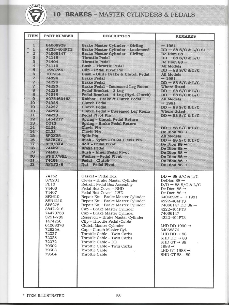
I have been advised by Mike Brotherwood in the U.K. (one of the few constructors remaining in business who repairs Lotus Sixes and Sevens), that he has 9 original Ford 100E aluminum pedal brackets for sale for the Lotus Seven models (Series 1, 2 and 3). Each one comes complete with the pedal pivot pin installed, and they are in various conditions ranging from very good to some with rust on the pins. Prices may vary, but I just purchased one for £140 plus £26 postage (insurance included) to Canada (if it ever arrives with our postal system still in trouble!) I am not selling them for Mike Brotherwood, I just want to pass on the information should any Seven owner require one, perhaps replacing a Caterham unit that has had one of the bracket arm/lug sawn off for use with a cable clutch, and wishes to convert to hydraulic clutch operation? Mike can be contacted at: mikebrotherwood@aol.com He accepts Paypal, but please contact him directly as there may be other payment options you can use. W.
-
Just to advise that I have received information from Mike Brotherwood in the U.K. that he has some of the original 100E pedal brackets for sale if anybody requires one.. I have added this information to the parts for sale section W.
-
Hi Dave. That is very nice lacing. I used to do lacing when I worked for British Telecomm., and later a couple of Canadian telephone companies. It does keep the wiring neat and tidy, and the wax embedded in the string stops it from cutting into the cable/wire sheath. Nice job. W.
-
Where can I get a nose cone for a Series 2, Lotus 7?
EdWills replied to Bill's topic in General Sevens Discussion
Scott. My 1969 Series 3, built in October 1968 and fully completed by Lotus, had one of these clamps fitted either side to my Unirad built chassis. Lotus was still using Series 2 specification chassis/body units for the Series 3 in late 1968 into 1969, only requiring Unirad to add an extra bracket for the extended exhaust as well as seat belt fastenings to the chassis frame (with other additions to the car by Lotus). Unirad also used metal plates on either side of the two top wing mounting clamps to reinforce the clamps on the top tube in the form of a 'sandwich'. Arch never seems to have adopted this procedure, merely welding the clamps directly to the top tube. My car also came fitted with a front licence plate bracket, which the second owner made removable. At the time, there was a requirement in the province where I live, to have a front licence plate attached. This changed to a rear plate only, some time after. I have only seen a couple of photos of Sevens (Series 2 or 3) in the U.S. or Canada fitted with the front licence plate bracket (another removable one on this site in Edmonton, AB, Canada), and assume that owners sawed them off? There are old photos of Series 2 cars being loaded onto car carriers at the Lotus factory fitted with the bracket, but not many - on Simple Sevens for example - still sporting them. W -
Where can I get a nose cone for a Series 2, Lotus 7?
EdWills replied to Bill's topic in General Sevens Discussion
Hey Scott and Bill. Just found this post, and checked my files for other measurements on my Seven. For a replacement Lotus nose cone from Redline, Chris advised in 2020 that the replacement colours available are yellow, green and red. He also provided information that the inside measurement dimension - where it is held by the Dzus fasteners on the top of the chassis - is 25-1/2 inches with easy flex of 1/4 inch larger or smaller. I have checked a nose cone that I purchased from Mick at Xtra Special Sevens, and his is slightly narrower than this to fit nicely on the chassis. Arch (Bruce Robinson) advised me some time ago that their "current Lotus S2/3 bonnet is 37 1/2 inches (measured along the centre line). This would have been an average length of what had been previously produced". It came without any cut-outs for the 1/2 ice cream scoop or the cut-out for the downdraught Weber carb. He later advised that Arch were no longer selling the Lotus bonnet, but I'm not sure if this was temporary or permanent? My notes from my original car show that the the Lotus Seven nose cone from the very front to the Dzus fastener centre is 23-1/2 inches and the scuttle is 8-3/4 inches from top to bottom measured in the middle. The centre of the Dzus bracket on top of the chassis, to the front of the chassis is 12-1/2 inches for a Lotus Seven S2/3, and this is confirmed with other Seven chassis drawings on the web. I don't know if they are still posted, but Pat Prince who is/was a Seven chassis builder in the U.S., posted a series of drawings for a S2/3 taken from a Lotus Seven chassis. Likewise another gent posted measurements from his Series 2. Just a note: There were two chassis builders of the Series 3 - Unirad and later Arch. Each built their own jig with measurements supplied by Lotus. My replacement Arch chassis does not exactly correspond with measurements that I took from my original Unirad chassis. There is not very much in it, and possibly of no consequence, but adjustments may be required if fitting panels, for example, from one to the other. If anyone requires other measurements, I can check the drawings I have from the various sources, to hopefully come up with a satisfactory answer. W. -
Ford Anglia 100E produced 1953 to 1959 (photo on wikipedia)
-
Sorry - pressed send before I loaded the photos!! W

-
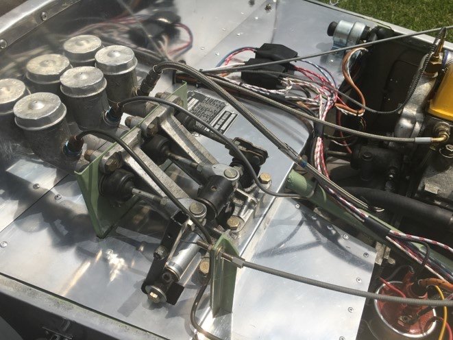
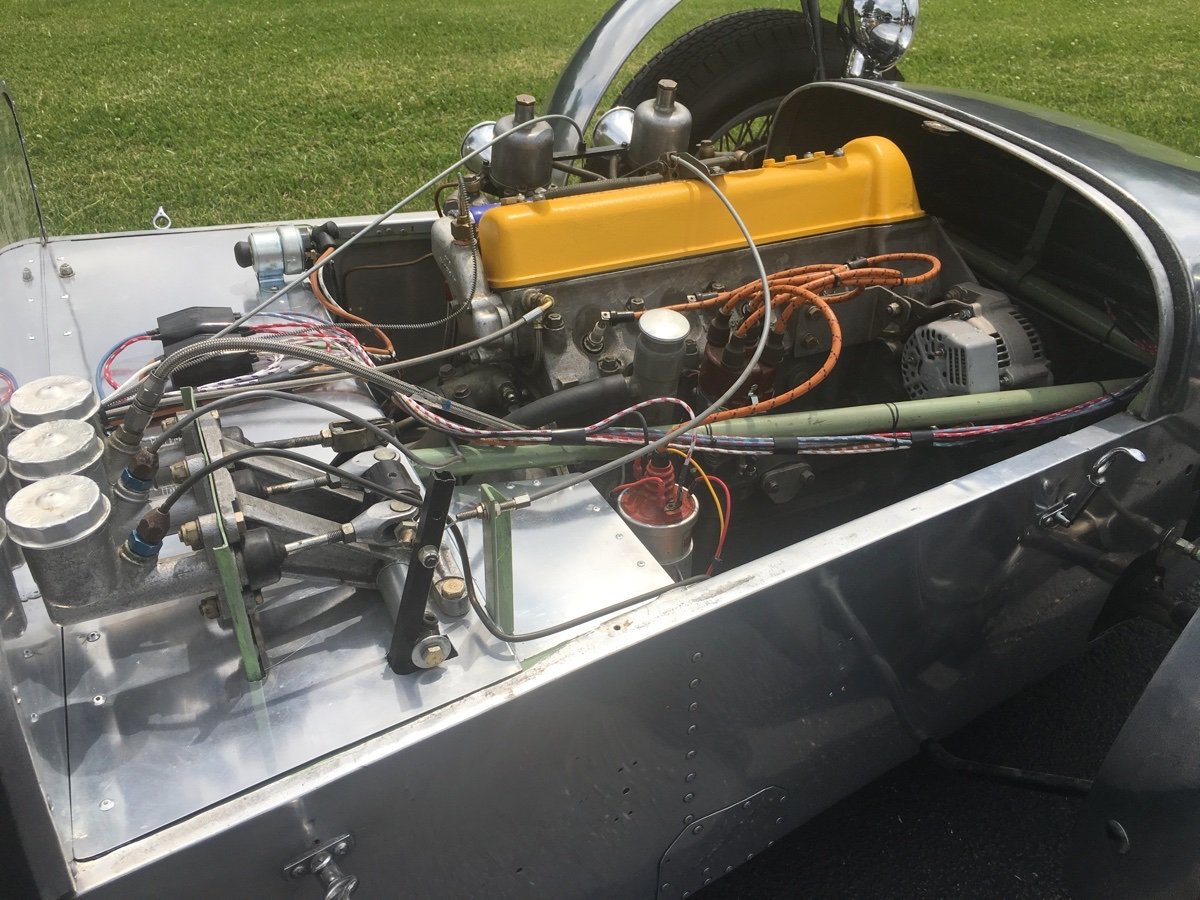
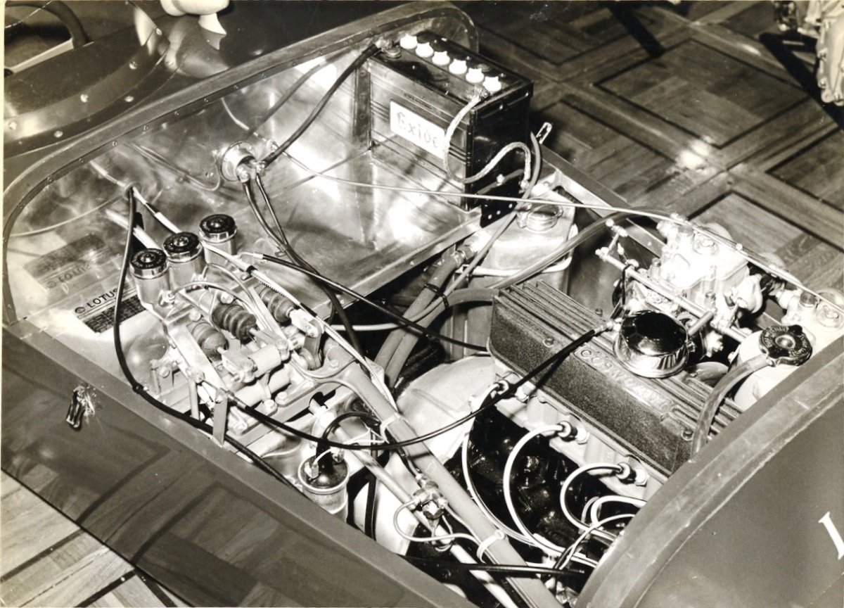
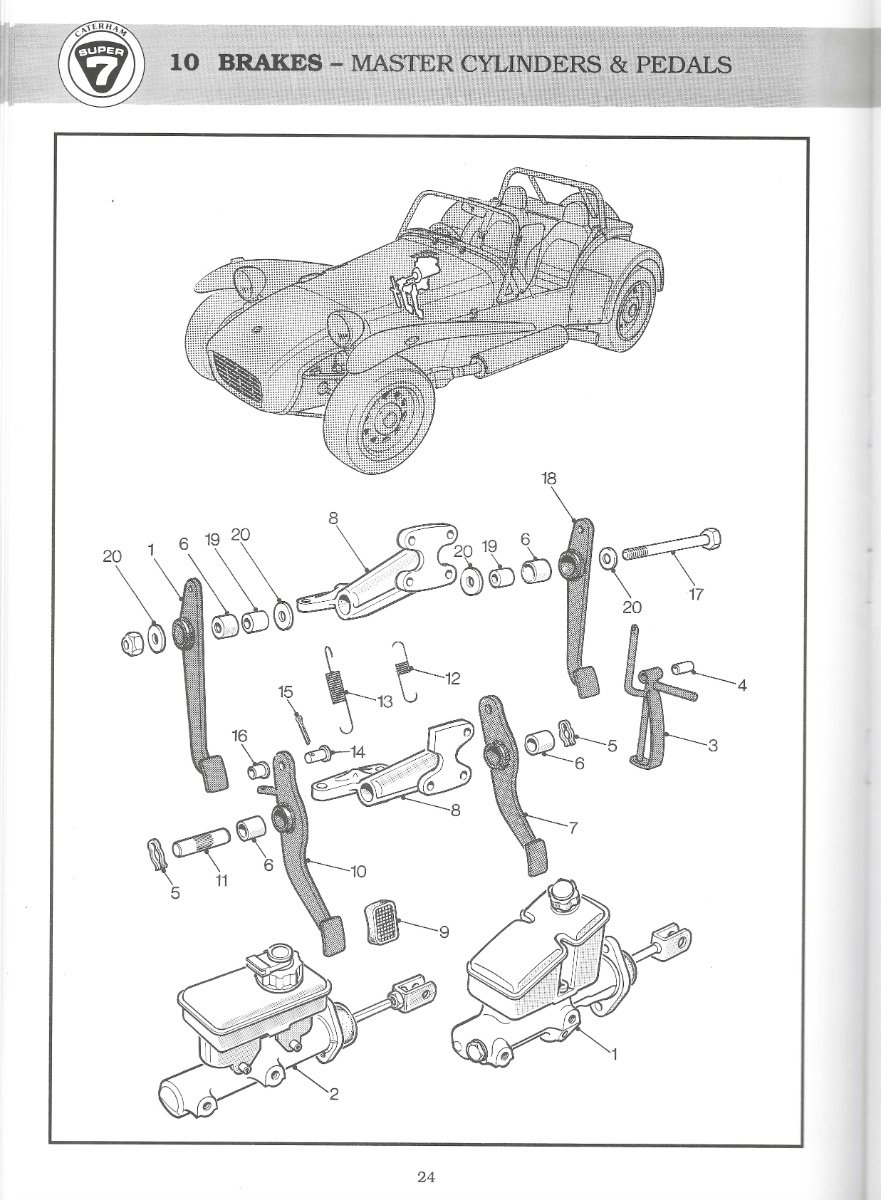
Joe, absolutely nothing wrong with your set-up. As long as any conversion is sturdy and safe, go for it. I have attached a couple of photos of a Series 1 owner's car with a brake bias bar set up (courtesy of Simple Sevens). Similar to Joe's system, a metal plate has been used to strengthen the two 100E brackets with the second one being mounted beside the original. Tilton Engineering manufactures an adjustable brake balance bar that is very suitable for a Seven (part number 72-250 for 2-1/2 inch centre M/Cs.), and fits perfectly between the brackets, allowing full adjustment, and permitting the brackets to then fit comfortably on the front angled bracket (just one extra hole required in the angled frame piece). A small extra frame bracket (from Arch) is required to be welded on to the square section frame tube (located behind the angled frame piece) to secure the bracket lug/ear of the second 100E bracket. Arch/Caterham manufacture/sell a replacement Lotus Seven clutch pedal suitable for bias bar modification (I purchased an original Seven clutch pedal secondhand) which allows for correct spacing of the 3 pedals. If you try to use the original brake pedal without modification, there is insufficient spacing available as it moves it too close to the accelerator pedal. With the Tilton bias bar pivot sleeve attached to the top of a clutch pedal, using 2 clutch pedals gives correct spacing, should provide good heel and toe control, and doesn't require unnecessary bending of the original brake pedal. If you want to return to just the one brake master cylinder, the brake pedal is easily replaced to return the car to as originally produced. I used an appropriate metal cutting hole saw to obtain the correct 'half moon' cut out for the pivot sleeve, and made up a jig which allowed my local Tig welder pal to correctly locate the bias bar pivot sleeve onto the top of the pedal for welding. It permitted him to centre the pedal as necessary (using spacers/washers) and get it all square. The pivot sleeve may then require reaming, as the welding process may cause it to shrink very slightly and not allow free movement of the bias bar bearing. Note: My second-hand original Lotus Seven clutch pedal had the pedal pivot bearing tube welded off-centre by the manufacturer (Universal Radiator?), so washers aided in centering it. I no longer require this jig (along with a suitable hole saw) if anyone wants to try this modification to the pedal. GMT/Lee Chapman Racing sells a clevis that is an exact match for the type used by Lotus and fits the M/Cs and the Tilton bias bar arrangement. As a thought, Tilton is in a perfect position - if they ever consider it - to manufacture new 100E brackets. Their engineering and manufacturing know-how is first class, along with their quality. Probably a minimum production run would require thousands of dollars to set it up, but not being anywhere near a business minded person, I do not know for sure. Cheers, W.
-
Here is a photo of the original 1965 Lotus 37 on its introduction at the Racing Car Show. Lotus used two of the 100E brackets, sawing off lugs on the second bracket to clear the frame and added an extra frame bracket to secure the second (right hand) bracket. They placed a balance bar in between the brackets and used one long pedal pivot pin instead of the originals presumably for safety, as trying to use 2 pedal pivot pins doesn't really work. Photo courtesy of John Watson - Lotus Seven Register. W.
-
Hi MV8. The solid steel pedal pivot pin is a tight push fit into the bracket. The hole in the bracket to accept the pivot shaft pin is slightly tapered, and the pin will only come out (or go in) - without damaging the bracket - one way (I recall that it inserts from left to right when looking towards the front of the car, but I will have to check). It can be safely removed by placing the assembly in a large vice (I used a 5 inch vice with protected vice jaws), then using a suitable sized socket (or some tubing) press the pivot pin out. The pivot pin is knurled in the middle to ensure a tight fit. With the brake and clutch pedal mounted on the shaft, 2 'omega' shaped square section spring clips hold the pedals on. The phosphor bronze bushes inside the pedals are a push fit, and I used suitable sized sockets to push the old ones out, and the new ones in. I sourced mine from the original Redline Company, but the new one may also be able to source these. I did a recheck, and there was also a Ford Anglia 100E produced and built in the U.K. and Australia. It was not the same shape as the later produced Ford Anglia that had the raked rear window area and which was featured in the Harry Potter series. If you check Wikipedia for Ford 100E, it shows the variations of the car all looking much the same. The 100E series was a smaller version of the Ford Consul range. There was even a Ford Escort 100E version long before the later, very successful Ford Escort that spawned the highly successful Mexico car. Scott. Caterham also produced versions of the bracket for their various cars and would cut a lug off for cable clutch versions. Hope that the GMT bracket suits the purpose. W.
-
Hey Scott. As noted by Croc and yourself, Ford Pop 100E, Prefect 100E, plus Ford Squire, Ford Thames van (also known as the Thames Trader 300E) all probably used this bracket. I read that the bracket shown in your photo was fitted upside down in the Ford application. Lotus of course placed it the other way up. I purchased one of those brackets from GMT (originally Lee Chapman Racing), the casting was fine, but whoever machined it after it was cast didn't do a great job and it turned out very crooked. At $198.00 U.S., obviously not cheap. I sent it back for a full refund, and later found that Mike Brotherwood in the U.K. had one for sale at a reasonable price. Check out his website for Seven parts. A company now long gone called Neal Products, San Diego, California (spare parts may be available second-hand?) manufactured a slightly similar looking bracket for their brake master cylinder set-ups. They produced brake bias bars and other brake components - all of very good quality. A shame that they went out of business. W.
-
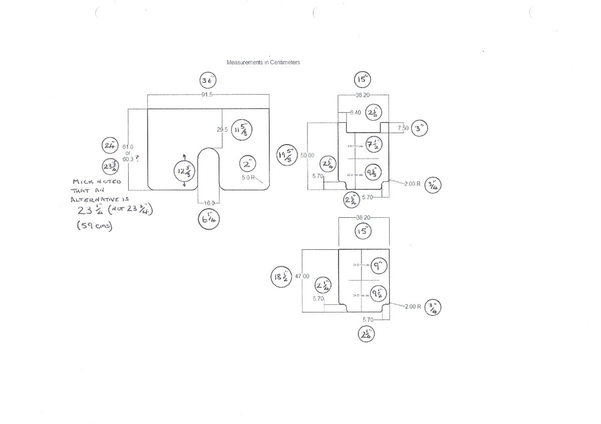
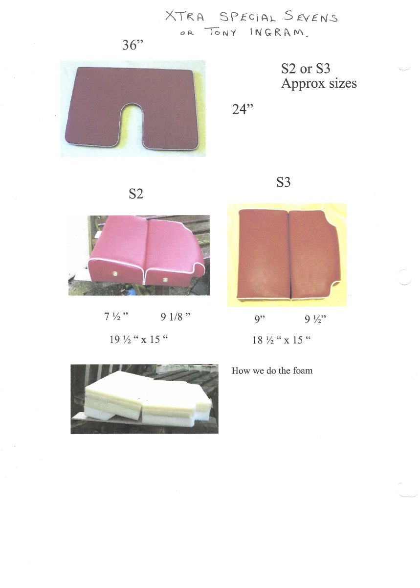
Just a P.S. Not sure why Mick drew the Series 3 seats without the front wooden seat 'tabs' (and produced them 1 inch shorter) as my Series 3 certainly had the wooden plywood extensions on the front and exposed to the elements. I have seen an alternative type of seat squab on later produced Series 3 cars, so obviously the seat manufacturers at the time made slight design changes. EW
-
Hi MV8. A very good idea if the seat cover manufacturer has not included mesh vent ports in the sides of the seat squabs. A few years ago, a very helpful Seven owner in the U.K. (via the lotus@se7ens forum) introduced me to a U.K. seat manufacturer called Aldridge, who also produced manufactured seat covers for Europas and Elans. After producing the seat covers for the U.K. Seven owner, and myself, the company advised that due to the time it took to produce them, and the labour involved, they politely advised that they would not be doing it again. But - perhaps they may be persuaded to reconsider? They sourced the identical vented basket weave vinyl as used by Lotus, and hot melted the exact same seams into the material. Round brass vents were added to the squab sides. Failing Aldridge, the Caterham U.K. seat manufacturer - Oxted Trimming - may be a good choice. EW
-
Your choice of course, but 3/8 inch thick ply may be a tad too thick, and can still warp. To avoid the possibility of warpage (wood has a mind of its own as we have all experienced probably?), you can use varnish or paint to seal the ply, on each side and the edges. No guarantees it won't warp, but worth doing. Water based varnish or paint will raise the surface structure of the wood, so sanding may be required after treatment. Lotus used a black painted thin ply sheet for the boot top also. On my old seats, 1/4 inch ply was used by the Lotus seat manufacturer. The previous owner discarded the wood boot top, and used sheet aluminum instead. I used a hand stapler to reattach my seat covers as the original wooden base was starting to rot and develop mold (mould?). I used 3/8 inch staples through the seat covers into the varnished ply. Scott, on your chassis, and on my new one, Arch welded in a 1 inch square tube at the bottom of where the seat back rests, but Lotus never included this in the Series 2 or 3, so if this extra tube it fitted, it may force the bottom of the seat back forward a little bit. If refitting used seats to a chassis that has this tube added, it will mean that the length of the seat squabs may require adjustment (slight shortening) either at the front 'tabs' or in the total length starting at the back. For all of the suggested 5.7 cm inside radii, a 2 inch hole saw does the trick. EW
-
Hi. I think you'll find that those measurements came from Mick Beveridge at Xtra Special Sevens (now sadly out of business). Tony Ingram was importing the seat covers in the U.S. sewn up by Mick's wife, but Tony notes on his website that he is out of the covers. Tony would be able to confirm measurements for you though, as he has rebuilt his own Series 2. Cardboard cut-outs are a very good idea, as in some cases Caterham specified slightly different prop shaft tunnel widths from Arch depending on the chassis. In one case the prop shaft tunnel was 6 inches wide (seats were 15-1/2 inches wide + 6 inch tunnel width, and 1 inch x 2 lower side tubes to produce 39 inches wide total chassis width (Imperial Lotus measurement chassis built on original Lotus Seven jig). Arch (Bruce Robinson) advised me that the tunnel could be 5 inches wide (old Lotus chassis measurement) and therefore the seats could be 16 inches wide. Bruce provided another possible measurement that 5-1/2 inch tunnel width had been used, so there seems to have been enough variations for the need to make up a good template for your particular chassis. Don't forget to allow for the thickness of the seat material all around (to fit inside the chassis snuggly) when cutting out the plywood. 5/16 inch thick ply seems to be good, but perhaps 1/4 inch would be o.k.? In Canada we can get nice Baltic ply and also waterproof ply (not just for boat use) but expensive these days. I've asked on another Lotus Seven forum what comes first (not the chicken or the egg!), but does the seat back fit over the seat squab, or does the seat squab go in last to secure the bottom of the seat back in place? If the seat back fits over the seat squab, it might sit too high for seat belt mounts behind the seat back. (61 centimetres in the drawing equal to 24 inches - 60.3 centimetres drops 1/4 inch off this measurement). Mick's 91.5 centimetres seat back width equals 36 inches, so with the chassis rails of 1 inch each side for a total of 39 inches (this measurement was confirmed on my 1969 Lotus Seven chassis as well on various Seven diagrams on the web), there is a slight gap of 1/2 inch each side of the seat back which is o.k. with the seat cover material taking up the gap. Mick used double stacked foam to produce the raised front section of the seat squabs. Lotus had their seat manufacturer produce a one piece wedge for the front, but unless you happen to have a hot wire cutter (or can make one?), stacking 2 foam pieces may be easier. Good luck with your upholstery project. Check Tony Ingram's site as it shows the seat covers that Mick produced for the Series 2. Cheers EW
-
Hi Steve. According to the Tony Weale book, the 1700 Supersprint (my apologies, I thought that you had the 'Sprint' model with the A2) was fitted with the 'Caterham BCD' camshaft. Years ago I inquired with Caterham and the parts manger advised that the BCD cam was actually a 234 camshaft (Kent Cams product possibly?) with 1300 c.c. pistons fitted to the engine for higher compression ratio and Weale puts this at 9.75:1. The 234 cam is 280 degree inlet and exhaust with valve clearances cold at inlet: 0.022 inches, exhaust: 0.024 inches. The engine capacity is listed as 1690 c.c., and the bhp rpm is as you note, 135 @ 6000 rpm.. Kent describe the 234 as a 'superb sports road cam, flexible enough for use in a lightweight se7en, good for track day use'. Timing 37/63 73/27. Plug type NGK B8ECS. Just an fyi, James Whiting in the U.K. is a great source for NGK plugs for the Seven range. I tried my local auto parts shop, and they couldn't find some of the plugs listed for the original Lotus Seven or the Caterham variants in their NGK booklets. Maybe NAPA or similar can order them? Hope that this helps? Ed.
-
Hey Steve. According to Tony Weale in his book "Lotus Seven - Restoration - Preparation - Maintenance" the 1600 Caterham Sprint version was fitted with the A2 camshaft with clearances of 0.020/0.022 inches as standard. The h.p. rating for that car was only given as 110 @6000 rpm with 2 Weber 40 DCOE carbs. Weale included a note that the 1600 Sprint engine up to chassis CS3 4099 had clearances of 0.012/0.014 inches.
-
P.S. An aircraft welder friend recommended LPS3 to spray inside the frame tubes. His aircraft repair company uses this product, and it comes with a long and small diameter nozzle that can easily be inserted in a 1/8" or possibly a 3/32" hole. I purchased mine from a local Grainger store (no connection, just a satisfied customer) W.
-
Excellent advice from all, and Pegasus is very proactive in their search for handy tools. One way to hold the rivet while drilling is to use a small centre punch (or a sharp pointed nail possibly?), lightly tapped into one side on top of the rivet and angled away from the drill bit, then drill away. The punch should stop the rivet from spinning. Either that, or wedge a flat tipped screwdriver that has been ground down to a sharp edge, as per MV8's suggestion. Don't be too concerned if the hole you are left with is a tad on the large size, as Carroll Smith in his excellent series of books, suggests that a No. 30 drill for 1/8" rivets, or No.20 drill for 5/32" rivets allows for correct expansion and clearance when inserting a 1/8" or 5/32" rivet respectively. A comparison chart that I have from Snap-On shows that 5/32" is 0.1562" and a No.20 drill is 0.1610". If you do happen to drill too much oversize, go to the next size of rivet for replacement, in the case of 5/32" go to 3/16". If, when doing a complete ally body removal and chassis clean-up, you really feel the need to remove those drilled out rivet pieces (tails?) from the chassis inside tubes, a hole can be drilled in the very front square blanking plates top and bottom (I used 1/2", but smaller may be o.k.?), and with the chassis held/propped up at the rear at a good angle, the rivet pieces will roll down the round and square tubes and can be vacuumed up at the very front of the chassis. I did this with my old Lotus Unirad chassis (O.K., anal rules?), and removed most of the rivet pieces as the top and bottom tubes from front to back are mostly open even when 3/4" tube is connected to 1" square tube. The holes in the front can then be welded or brazed shut as they pose no problem to chassis integrity of course. Only the cross and down tubes will retain the rivet 'tails', but there are far fewer than in the main chassis rails. Cheers, Will
-
Hi Andy. I just checked my parts boxes, and found some original chassis bushes that were intended for repairs on my old Lotus Seven chassis. These bushes are 0.691 inches o.d. (my equivalency chart says 11/16 inches is 0.6875 inches), and the i.d is 1/2 inch (in your original post you mentioned 5/8 inches i.d.?) and a half-inch bolt fits snuggly inside the bush. These bushes are over 1-1/2 inches long so they can be reduced in length for a good fit. They are free if you don't mind paying the postage, but, (here's the big 'but') Canada Post is on strike, and if you are in a rush for them to complete a project, I don't know when they can be posted to you. As the outside diameter is slightly larger than you require, (and also the length of course), a competent machinist can reduce these to your specification. A local high school with students learning the trades may be a possibility if permitted (without incurring legal liability problems?). To do some welding jobs for me, I approached a local high school in my city, and the shop teacher advised that for a box of doughnuts for his students, he would do some work for me for free. Not too bad a deal! Let me know if these would be suitable. Will
-
Just a note on the bolt type for the water pump pulley (and fan blade attachment fitted by Ford on some of their older Kent engined vehicles). The pulley hub may be threaded for metric bolts not Imperial. A Quinton Hazell manufactured water pump on my 711M engine has a metric thread. It requires metric bolts M8-16. Mine are 8.8 grade nickel/zinc coated, 1/2 inches long (slightly longer if a fan blade is attached). Burton carry a new QH water pump on their site and similarly advise that the required bolts are M8. Will.
-
Not sure that this will help as the Caterham catalogue I have only goes up to 1991.