Yoram
-
Posts
257 -
Joined
Content Type
Profiles
Forums
Store
Articles
Gallery
Events
Library
Everything posted by Yoram
-
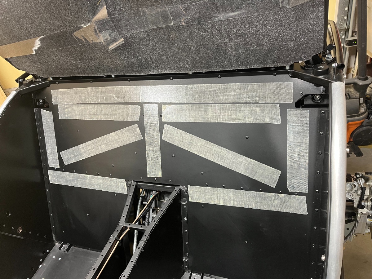
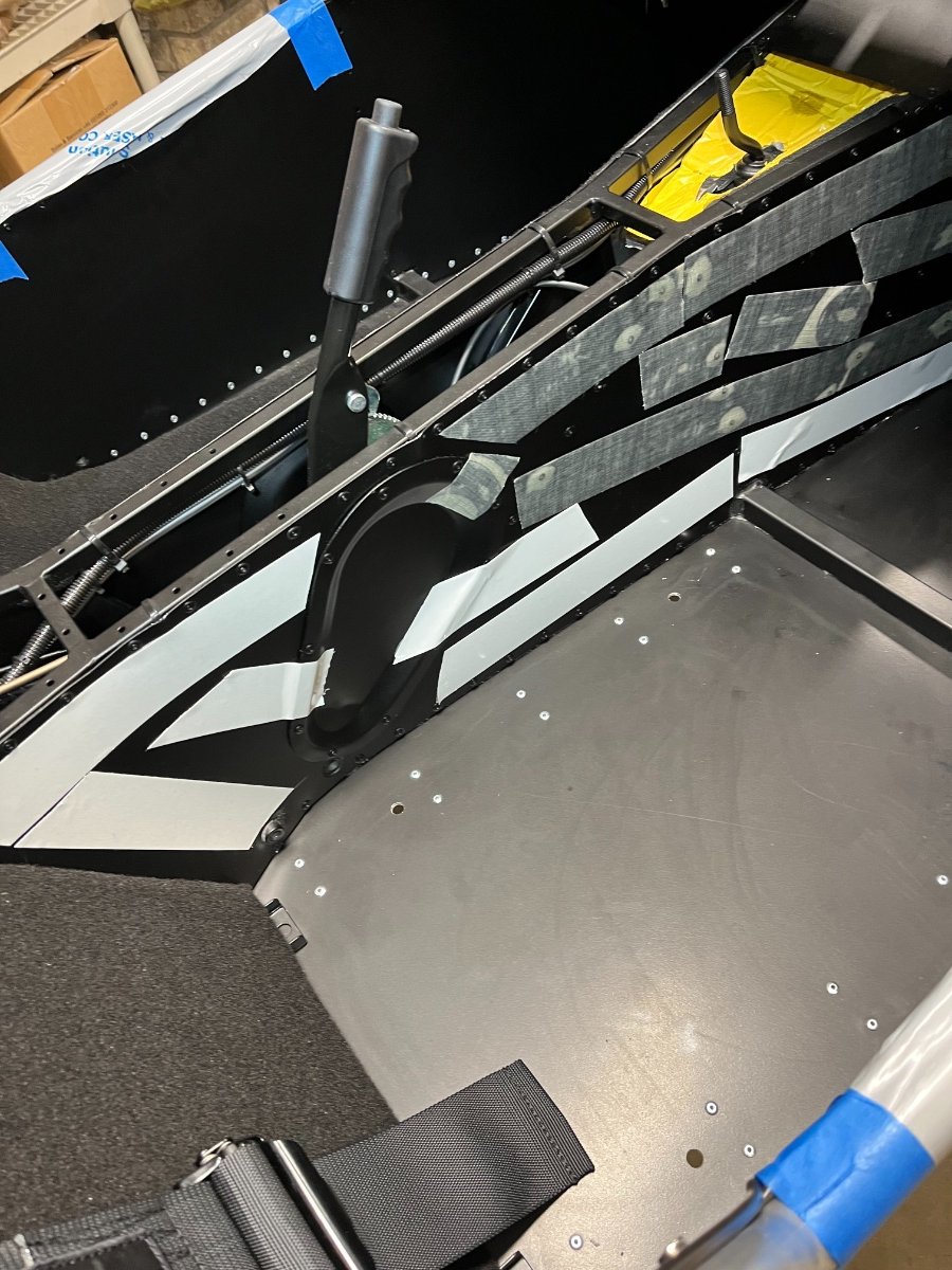
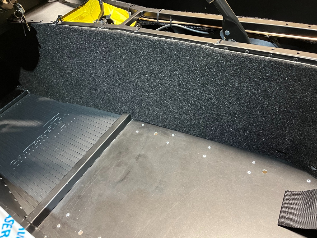
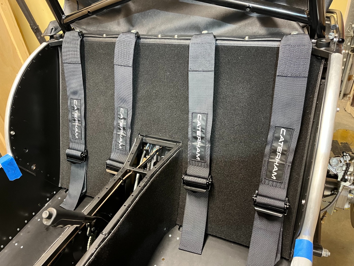
Interior - Part 1 In the meantime I made some headway on the interior. Here are the main steps in sequence: Carpeting: The carpeting consists of one large piece on the rear bulkhead ("back carpet" right behind the seats), and two long pieces for the sides of the tunnel. The carpets need to be glued in place. Per suggestion from Josh of RMC I used two sided carpet tape instead of adhesive -- much less messy to apply. In addition there are two thick rubber mats for the footwells. They can be anchored in place by drilling the floor and installing snaps but I decided to just lay them down. They are very thick and stiff and fit snugly in the trapezoidal wells and cannot move. Both sides needed to be trimmed a bit along the sides toward the front to fit. Back carpet held at the top by temporary bolts at harness attachment points and taped to roll bar while applying the carpet tape to the bulkhead: Back carpet in place. Corners at top of tunnel needed to be trimmed off to fit flat. Tunnel carpet tape in process: Tunnel carpet complete; foot well mat also visible: Shoulder harnesses: My car has the 4-point harnesses and Track Day roll bar. I installed the shoulder harness at this stage to help hold down the top edge of the back carpet which get wrapped around the upper cross beam. The supplied 45mm long bolts are too long to fit in the outside positions (and shorter than the 52mm ones shown in the IKEA guide!...), so I ordered and installed four 7/16"-20 x 1.5" Grade 8 zinc-aluminum coated hex head ones. They thread all the way through the bosses in the cross beam so I have no idea why any longer bolts are needed. Applied ThreadBlocker Blue and torqued to 40 Nm per the IKEA guide (2015 text guide shows 47 Nm). Continued in Part 2...

-
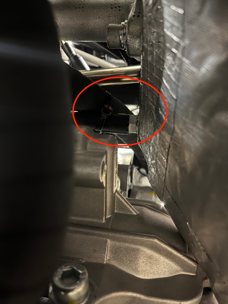
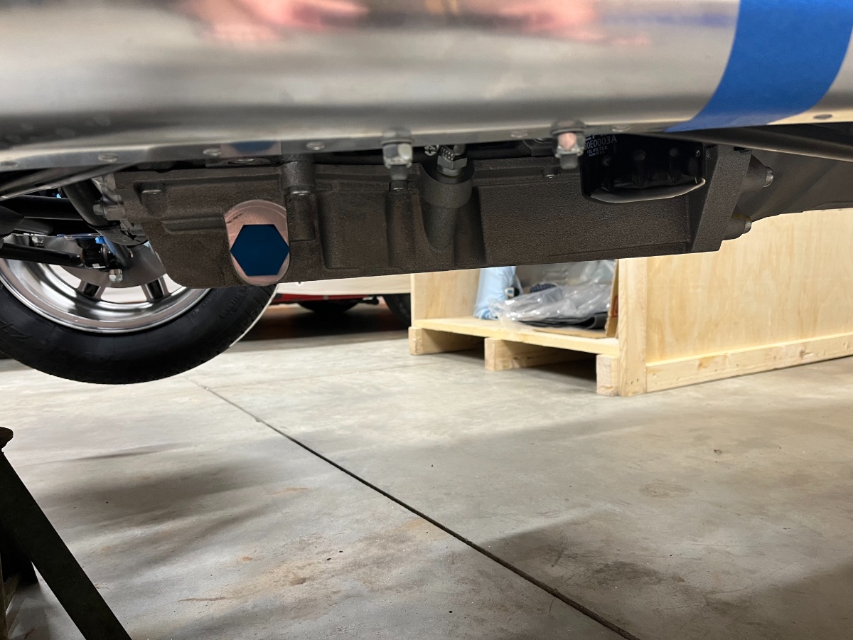
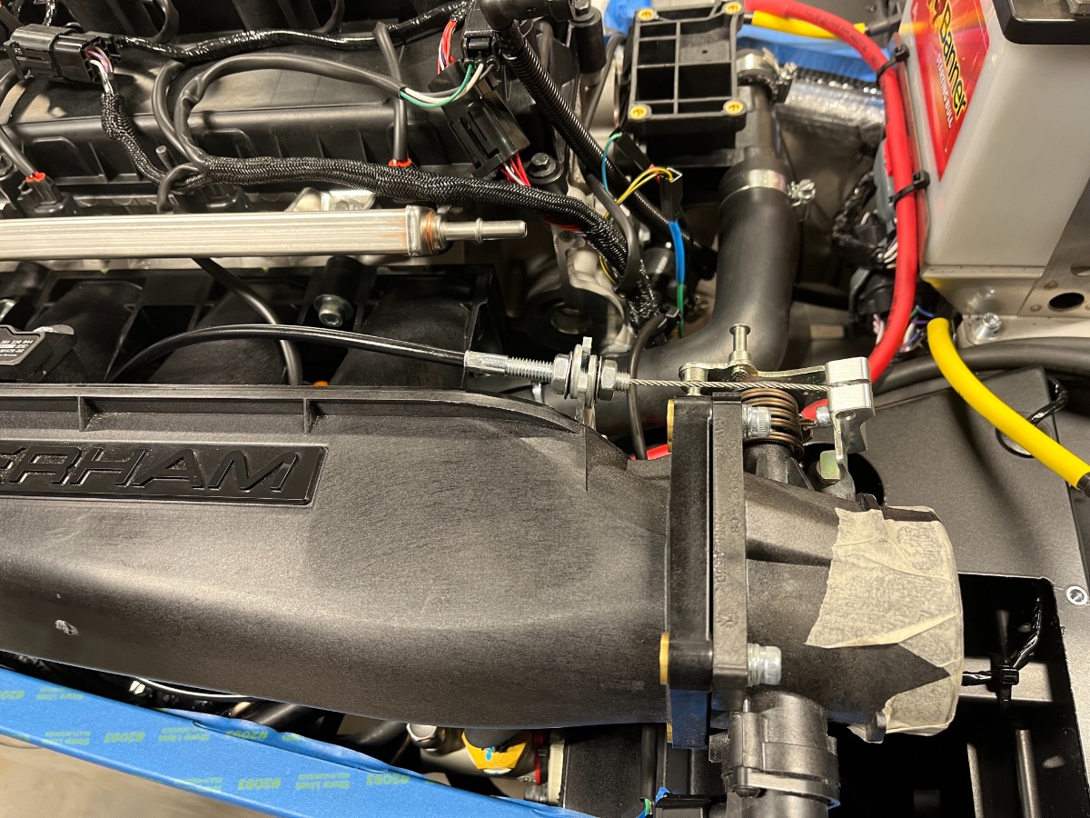
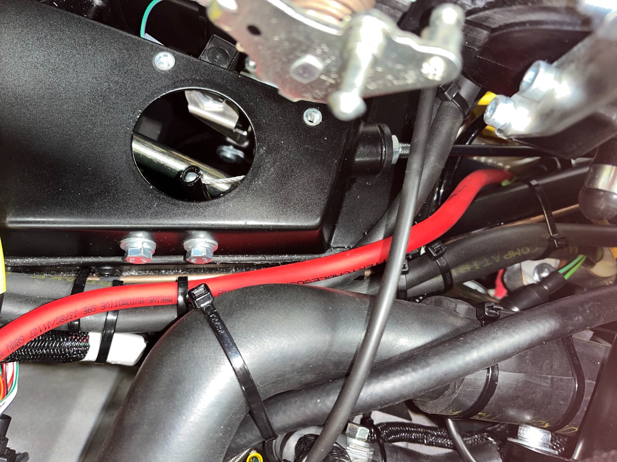
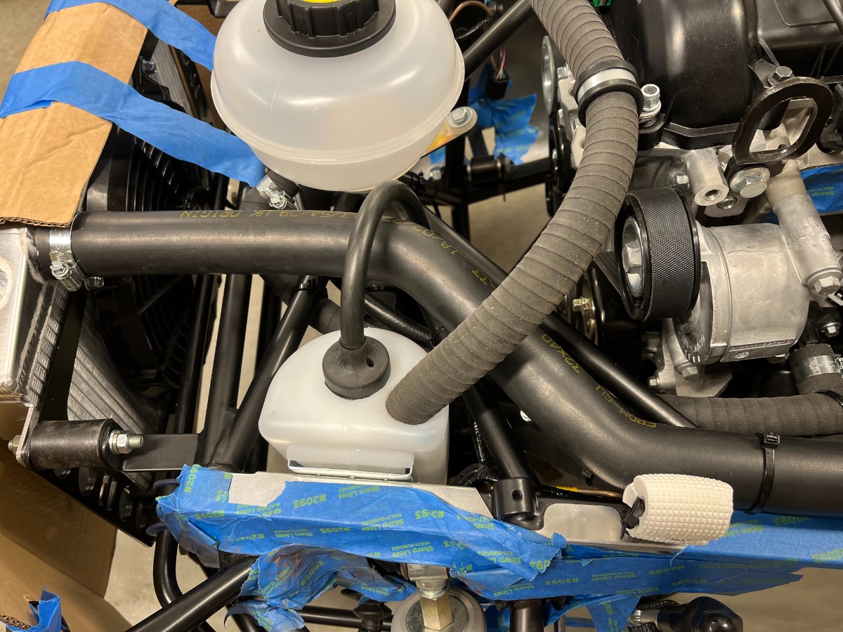
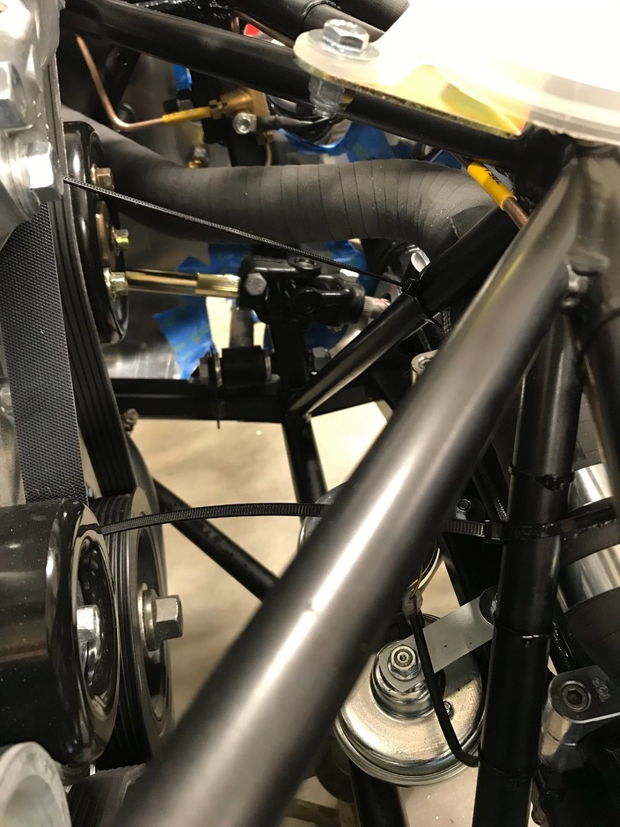
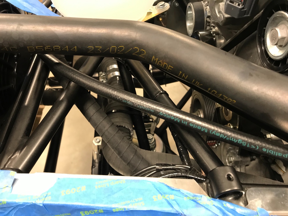
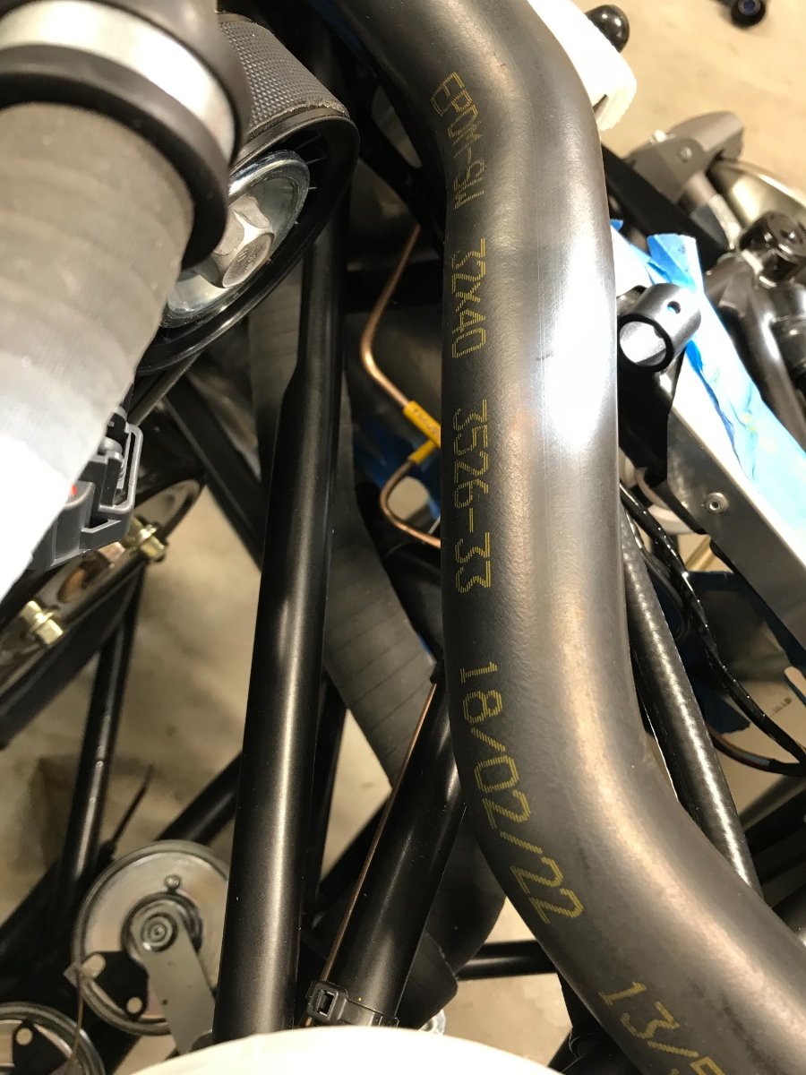
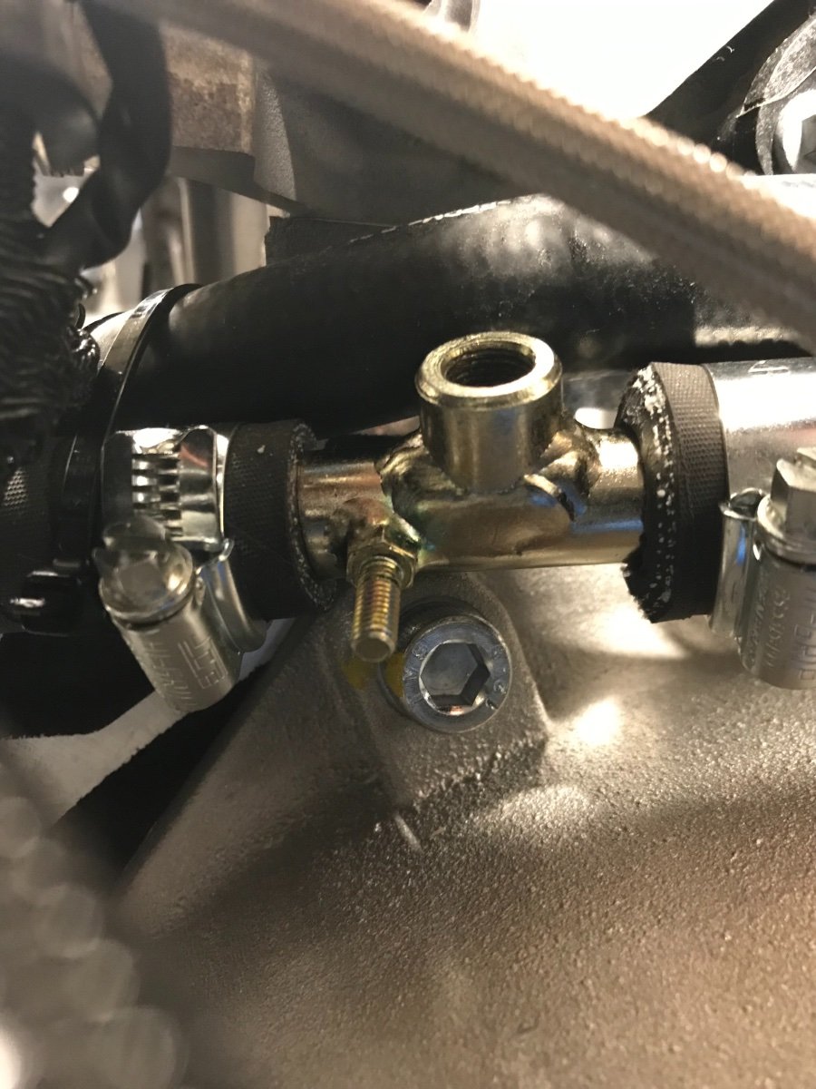
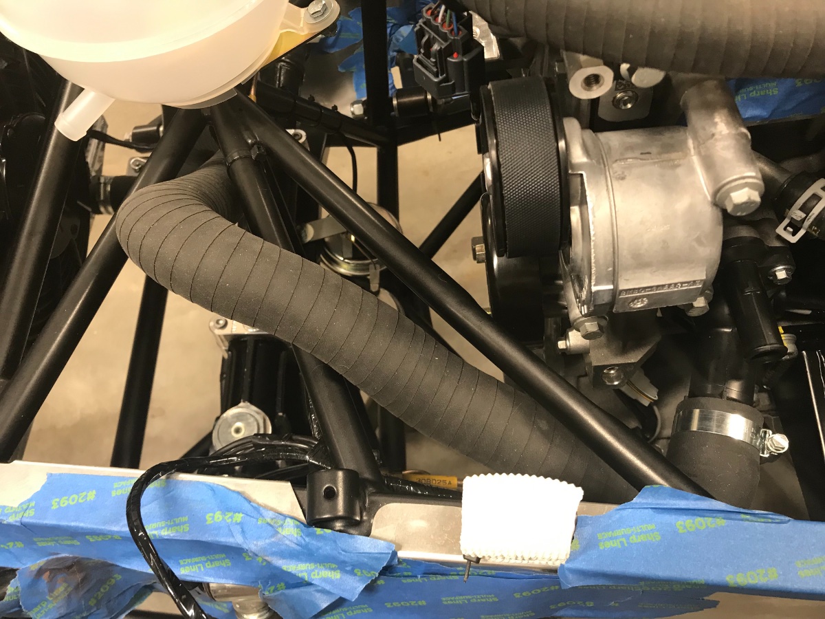
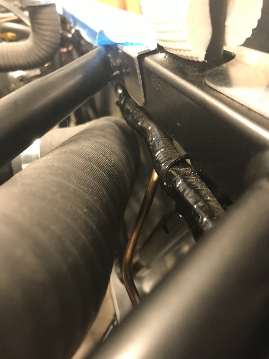
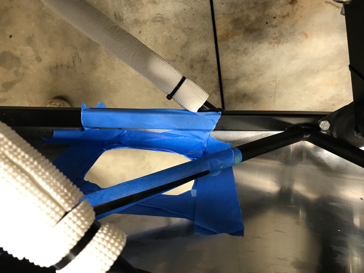
Throttle pedal stop (and plumbing, continued) As mentioned above, I decided for now to keep the hose routing and the pedal stop rod as is, and instead to pad the rod with a slit piece of 5/16" ID coolant hose and secure the problem hose to it with a zip tie. This way the hose is kept away from the steering shaft and protected from abrasion. The downside is that both ends of the hose are attached to the engine while the middle is attached to the chassis. However I figure there is enough length on both sides to accommodate the relative motion. Another downside is that I may need to undo this when adjusting the throttle pedal stop, but at least I will know what to do to secure it back afterwards. Here are a couple pics of this solution (the rod and hose "connection" encircled). The way I see it the whole issue comes from the fact that Caterham is cramming into the original 7 chassis dimensions an engine much larger and more complex than originally intended (and one designed primarily for East-West FWD application). Another manifestation of this is how much the sump sticks below the chassis. Ground clearance looks alarming...: I suspect the Sigma engine which I had ordered is better in this regard however I was upgraded to Duratec when the Sigma engines dried up during my wait period. It's like in life - nothing is perfect.... Cheers!
-
Thank you! Aware of most of these points but always helpful to get detailed guidance! I'm not sure I want to disassemble the throttle stop to cut the rod (trying to avoid spending time in the foot well not with my feet), so this morning I slid a sleeve onto the rod (out of a slit 5/16" coolant hose) and zip tied the problem hose to it. This at least ensures no contact with the steering shaft and no abrasion against the rod. I removed the zip ties securing the problem hose nearby onto the engine (indirectly) to allow unconstrained relative motion. Will post some pics as soon as I have more time. Thanks again.
-
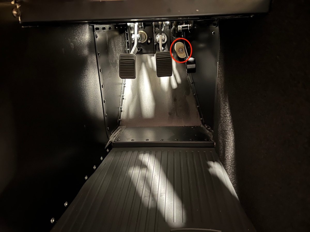
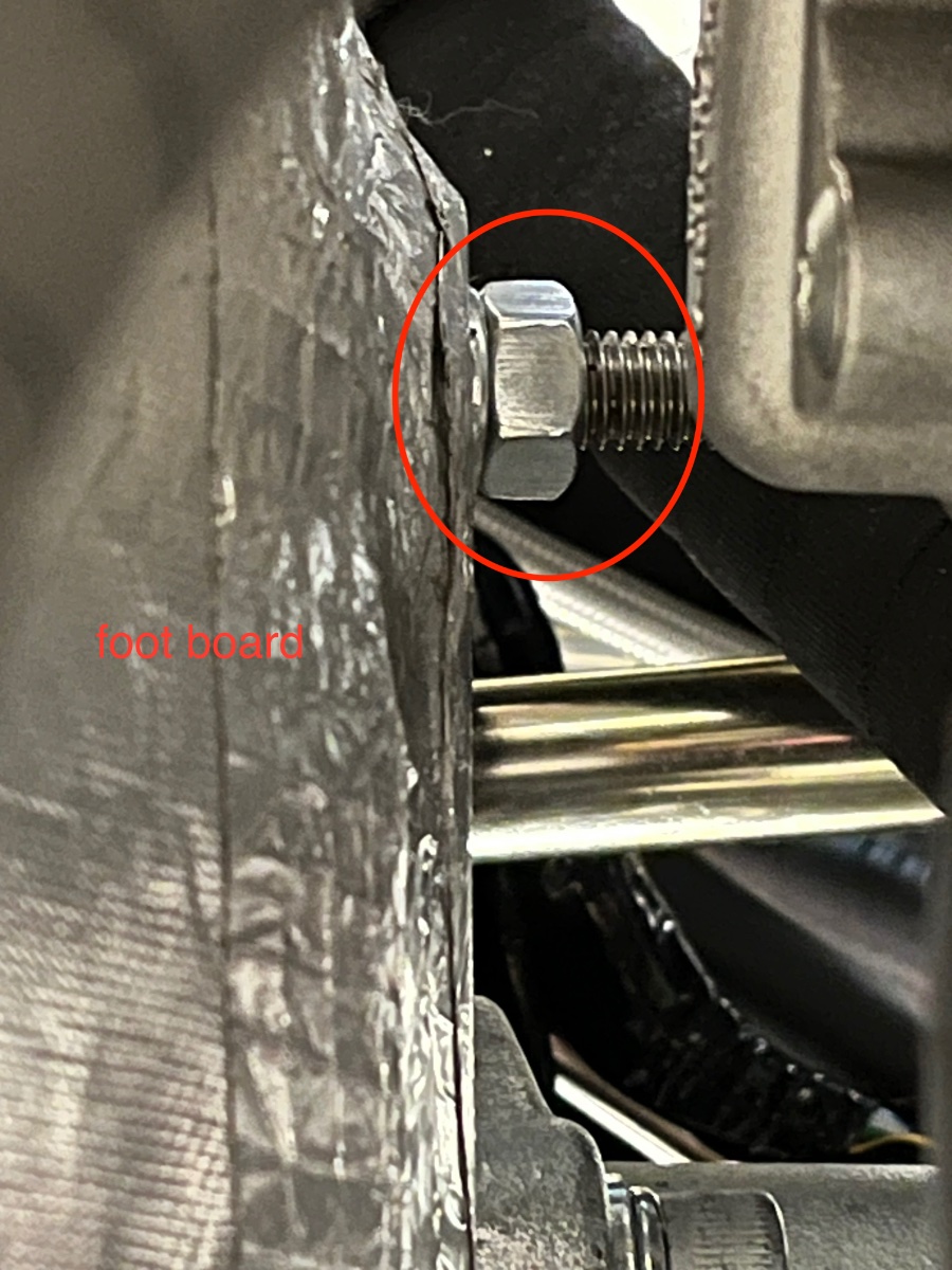
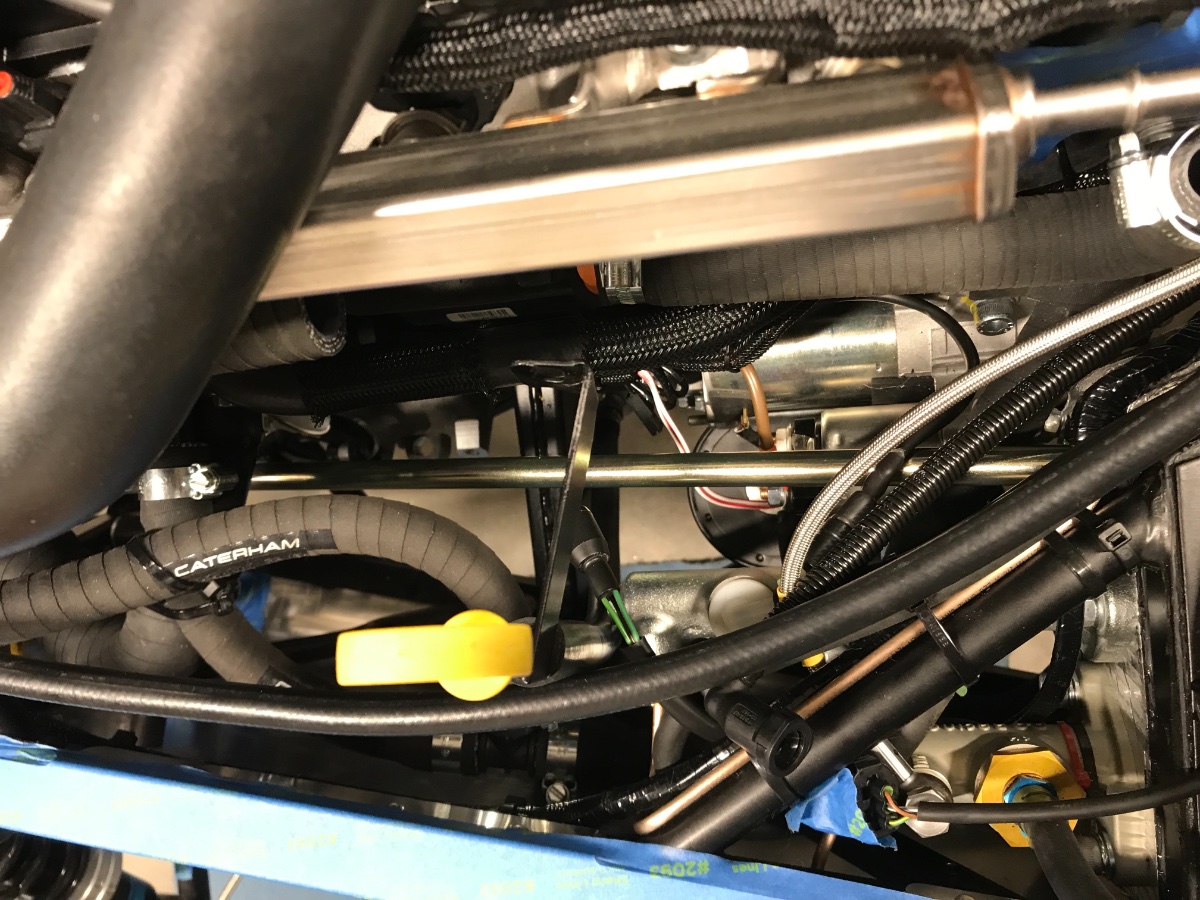
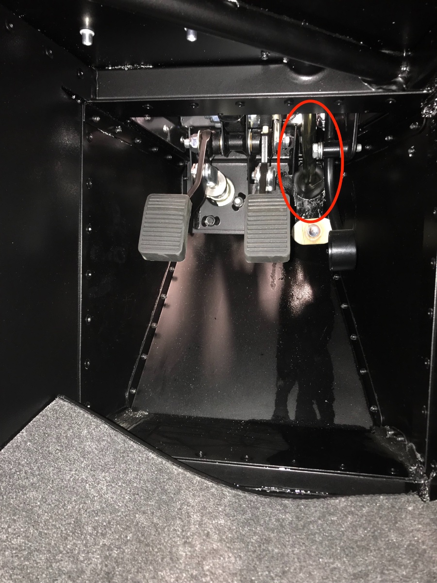
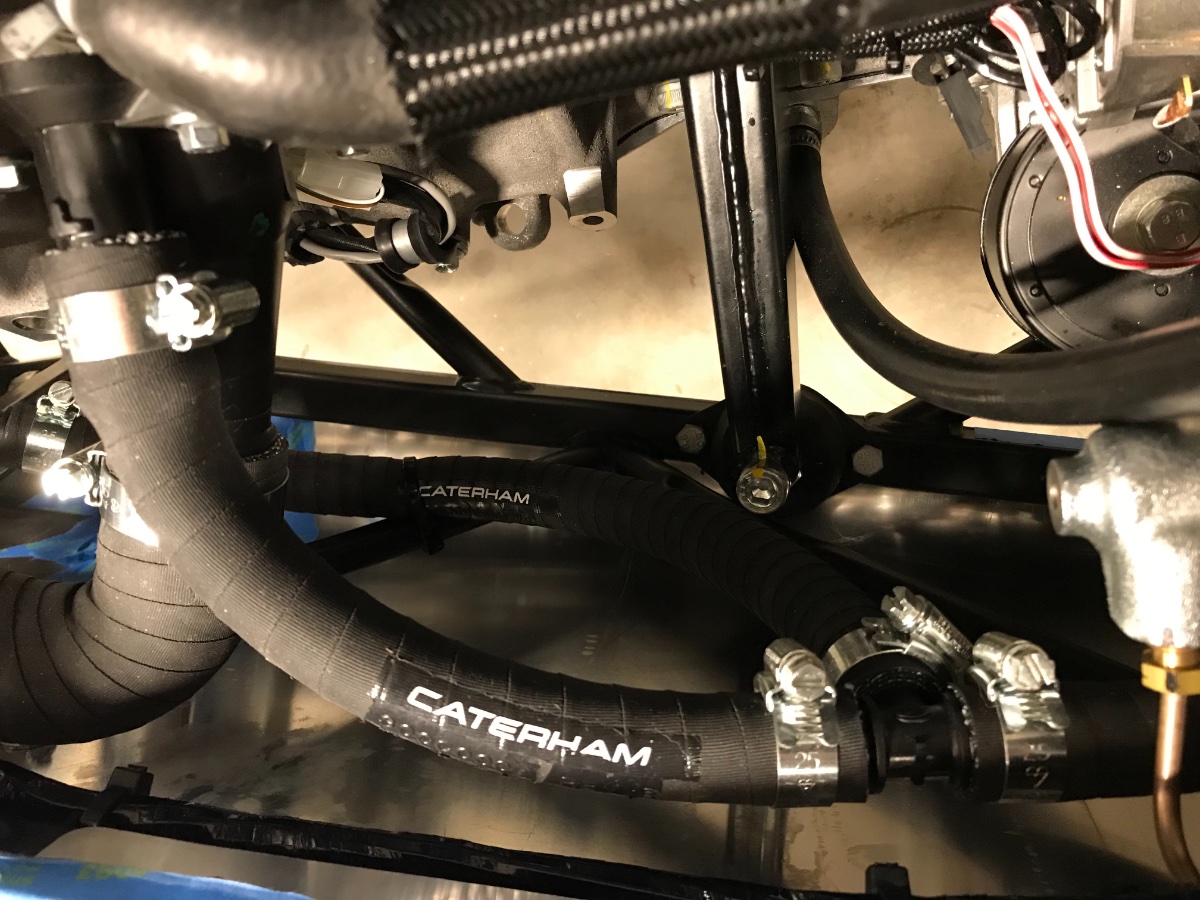
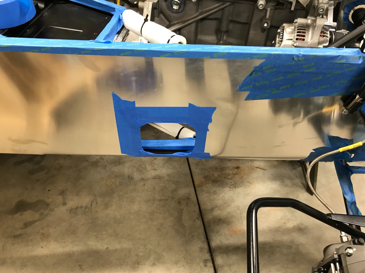
Throttle Pedal Travel Stop (and plumbing...) The throttle pedal travel stop has a long horizontal threaded rod which passes through the foot board and gets tightened with a jam nut from the engine bay. Unfortunately I do not have a good pic of this rod from above before engine installation or plumbing, and after the view from above is completely obscured... I'll go ahead and try to verbalize this whole thing as best as I can. The following pic shows the stop (encircled) viewed from the footwell. For engine installation I screwed the rod most of the way into the footwell so the it does not protrude and catch the bell housing on its way into the tunnel. Left in that position it would block free pedal motion, so it needed to be screwed back out (towards the engine bay). Final adjustment of the stop is supposed to take place after the engine has been run. However, for now it is not needed (I will not be using much throttle initially) but still needs to be secured with the jam nut so it doesn't flop about. I did that and verified that with the stop in its forward position the throttle can open all the way to its stop on the throttle body With all the plumbing and wiring in place (even before installing back the plenum) the only access possible is from below. Access from inside the footwell is of course worse and I precluded it. You first screw the rod out with your fingers and once it seems well out you tighten the jam nut. This part is a bit of a PITA, done with an open wench flipped back and forth, 1/6 of a turn at a time. Throttle stop threaded rod and jam nut (encircled), zoom view straight up from underneath: Now for the real issue: Once the rod was in what seemed like the desired position, sticking out into the engine bay, I discovered that it was pressing against the secondary coolant hose connecting the water rail to the modine ("problem hose"), and against the 5/16" expansion tank hose, and causing them to also just about touch the steering shaft. The throttle stop rod emerges from the foot board maybe 2" above the steering shaft, and the problem hose threads between them... Here is a view from underneath. The threaded rod is more visible here. The problem hose is marked with an arrow. To try to fix the problem: a) I ziptied together the two coolant hoses connecting to the modine to force the problem one away from the steering shaft (can be seen above). b) I ziptied the large expansion tank hose to the crankcase vent to help keep the problem one away from the steering shaft. c) I pulled out and completely re-routed the small (5/16") expansion tank hose higher up, just below the plenum, to de-congest the space around the steering shaft. A bit tricky with the plenum in place but actually in my view should be done at this stage. As a fringe benefit I was able to shorten the hose at the front, also by securing it to the rearmost chassis tubes which are free of electrical or brake line routing. A couple more views of the plumbing from underneath for fun: - The two curved secondary hoses connecting to the modine, and the "T" (thermostat / modine / expansion tank) on the right (actually towards the front of the car): Midway along the engine and steering shaft - dipstick hose on left, the "T", and the upper radiator hose connection to the thermostat: I am still not convinced that the problem hose will not touch either the throttle stop rod or the steering shaft (or both) in driving, so this remains a development task... Two lessons from this step: - Throttle pedal travel stop should be provisionally set to a forward position (protruding into engine bay) once engine is in place and before starting plumbing and wiring. That way its threaded rod can stake its space and hoses and wires can be routed accordingly. - 5/16" expansion tank hose should be routed last with the plenum in place to prevent interferences. Next post will cover throttle pedal height adjustment and who knows what else (a lot of stuff is happening in the background; it's a matter of budgeting time between life, build and documentation). Cheers!
-
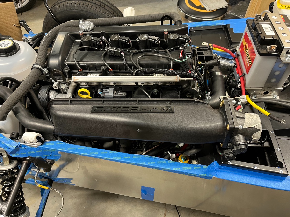
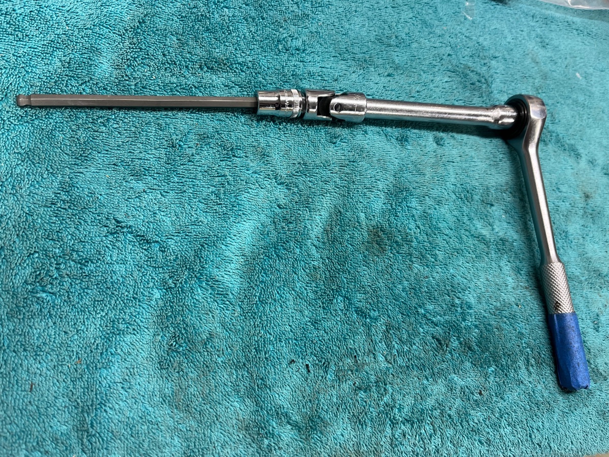
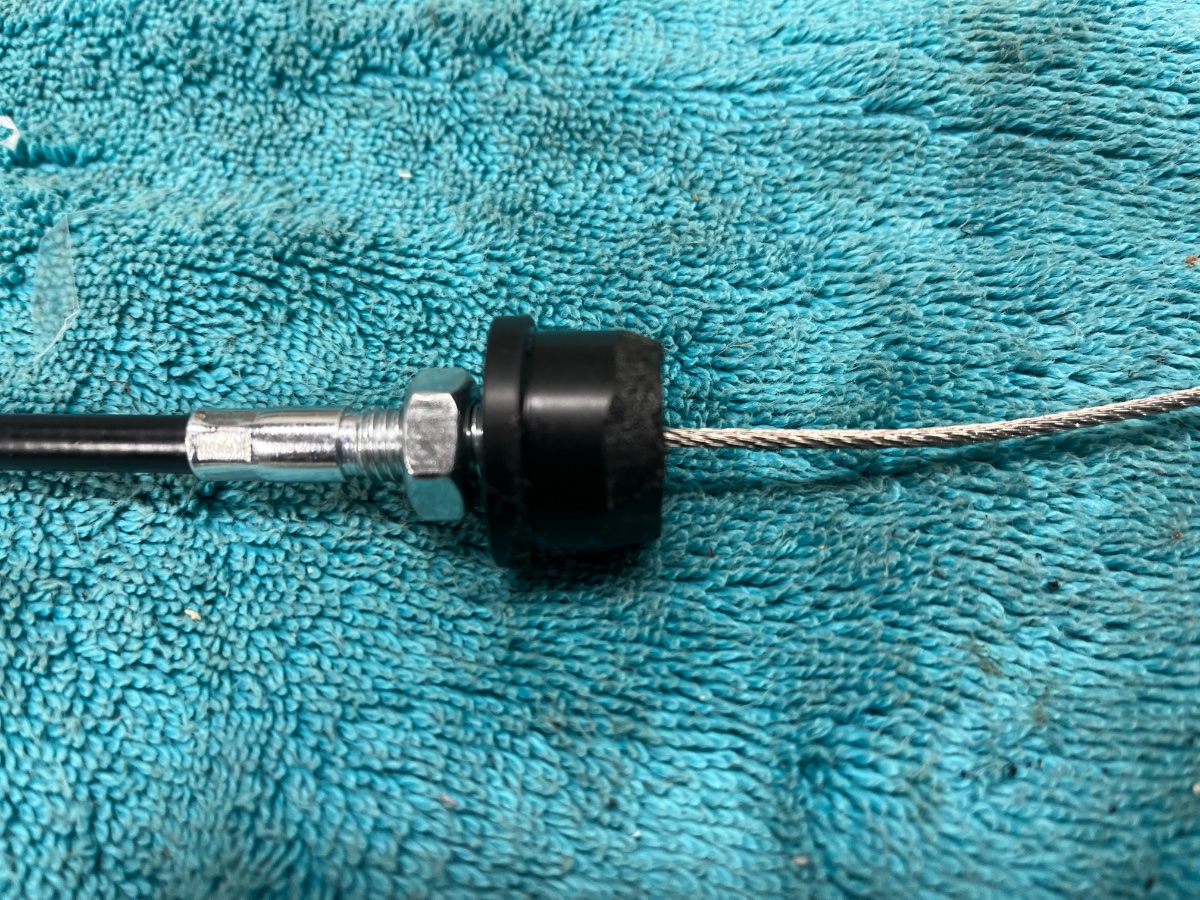
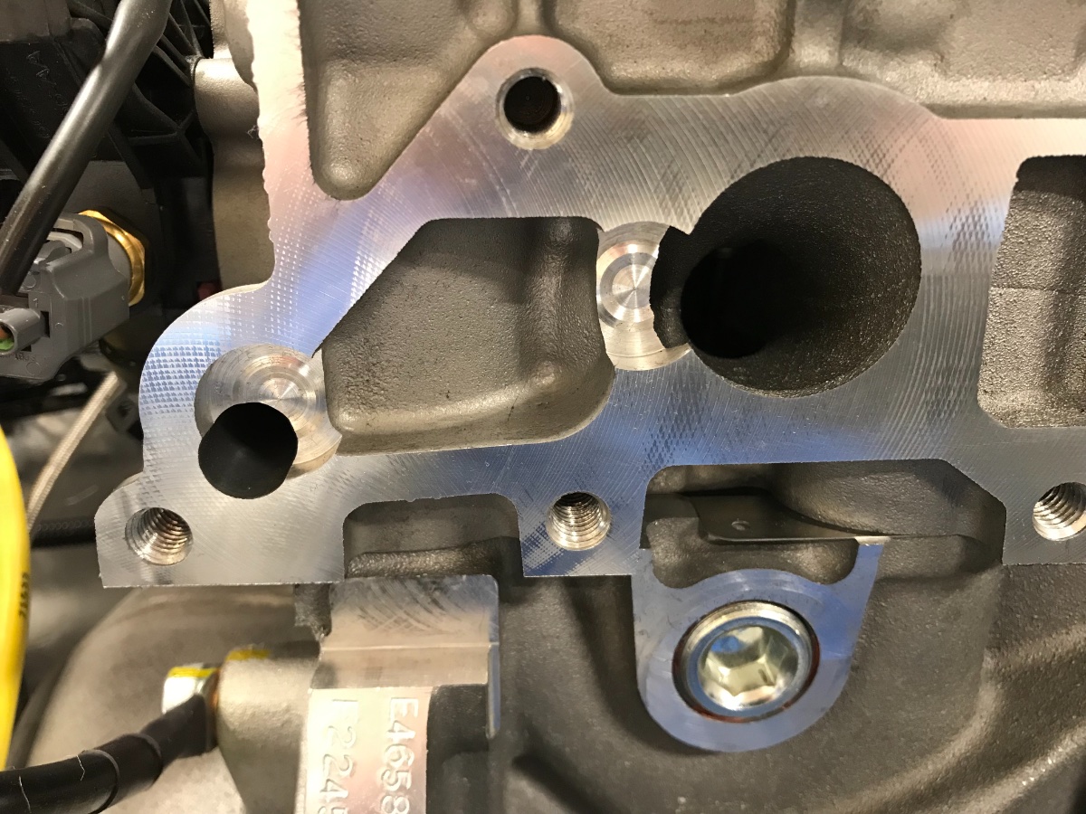
Plenum and Throttle Cable Plenum: Cleaned head port faces with alcohol and microfiber cloth after removal of masking tape. Need to make sure the thin gaskets remain fully seated in the plenum ports during installation. All 5 bolts were quite easy to insert and tighten from the side using a 6" long 6H bit with a spherical tip, a UJ coupler and a drive extension. The spherical hex tip held the bolts fine in horizontal orientation while navigating them into their holes. Tightened by feel due to no torque specs. Dipstick bracket shares the front upper bolt. Shortened the upper radiator hose a bit at both ends to shift the rear kink forward to in front and inboard of the plenum breather hose and to ensure good clearance from driver footwell. Rear elbow of upper radiator hose must be kept away from pedal box and from the engine loom. Also note cushioning from plenum bolt and clutch hose. The space between the engine and pedal box is very tight and very busy. Take care to route wiring away from dipstick. Plenum bolt installation and tightening tool. Lesson: Final length adjustments and tying down of the upper radiator and 5/16" expansion tank hoses need to await after plenum installation. Throttle Cable: Throttle cable installation was straightforward except the nylon bushing/insert for the pedal box hole needed some gentle Dremeling on the OD to fit in the receptacle in the pedal box. The pic shows the bushing at an early phase of the Dremeling. It actually required to take down the OD maybe ~1 mm along the entire length to the step to make it fit (apologies but I forgot to take a pic at the end). Throttle cable - plenum end: Cable adjustment needs to ensure the pedal rest stop is engaged at the same time as the closed throttle stop, such that the throttle closes all the way and the pedal does not have slack motion before starting to open the throttle. Adjustment is done at both ends. Throttle cable - pedal end (view from the right side): The part of the pedal above its pivot is a vertical tube with a slot at the top for the cable; squeezing the sides of the slot together with pliers will keep the ball cable end contained. The receptacle and the step of the Dremeled nylon bushing can be seen in the middle of the pic. The next post(s) will discuss provisional throttle pedal travel stop and height adjustments and plumbing revisions necessitated by the plenum and throttle pedal travel stop. Cheers!
-
Yeah. I was initially wondering why not mount the catch bottle in the front on the RH side where there is no congestion of hoses, but Josh Robbins advised against it due to the heat from the exhaust pipes, even though they are quite further back. I ended up sticking with the "official" location.
-
So let's see if I understand the chart: I pick the 6 AWG vertical line at the top and follow it down until I hit Curve 3. I then go across to the left along the horizontal line intersecting at that point, and read 9 ft in the 14 Volt column. Correct? And from the above intersection point on Curve 3 I follow the nearest sloping line up and read 125 amps. Which is less than ~180 amps but since my length is 4x less at <2 ft I'm good, eh? And there may be some reserve to accommodate my copper washers?... Thank you for this!
-
You are obviously correct regarding no relative motion. The intent of the shimming is to avoid bending the lugs and cables, but I will take a look at your suggestion. As to the AWG ratings, I don't know the AWG of the original cable. I specified the custom made one based on the OD of the original. It worked out to be 6 AWG at the nearest (greater) OD. 6 AWG copper is normally rated for ~60 amps so I figured it should work. Thanks!
-
Didn't know that!! I thought these were introduced with direct injection engines... Yes, my washer bottle which I have yet to install also has the exact same bracket. Have you looked into having yours refinished, or ordering a replacement catch or washer bottle kit from Caterham, whichever is cheaper?
-
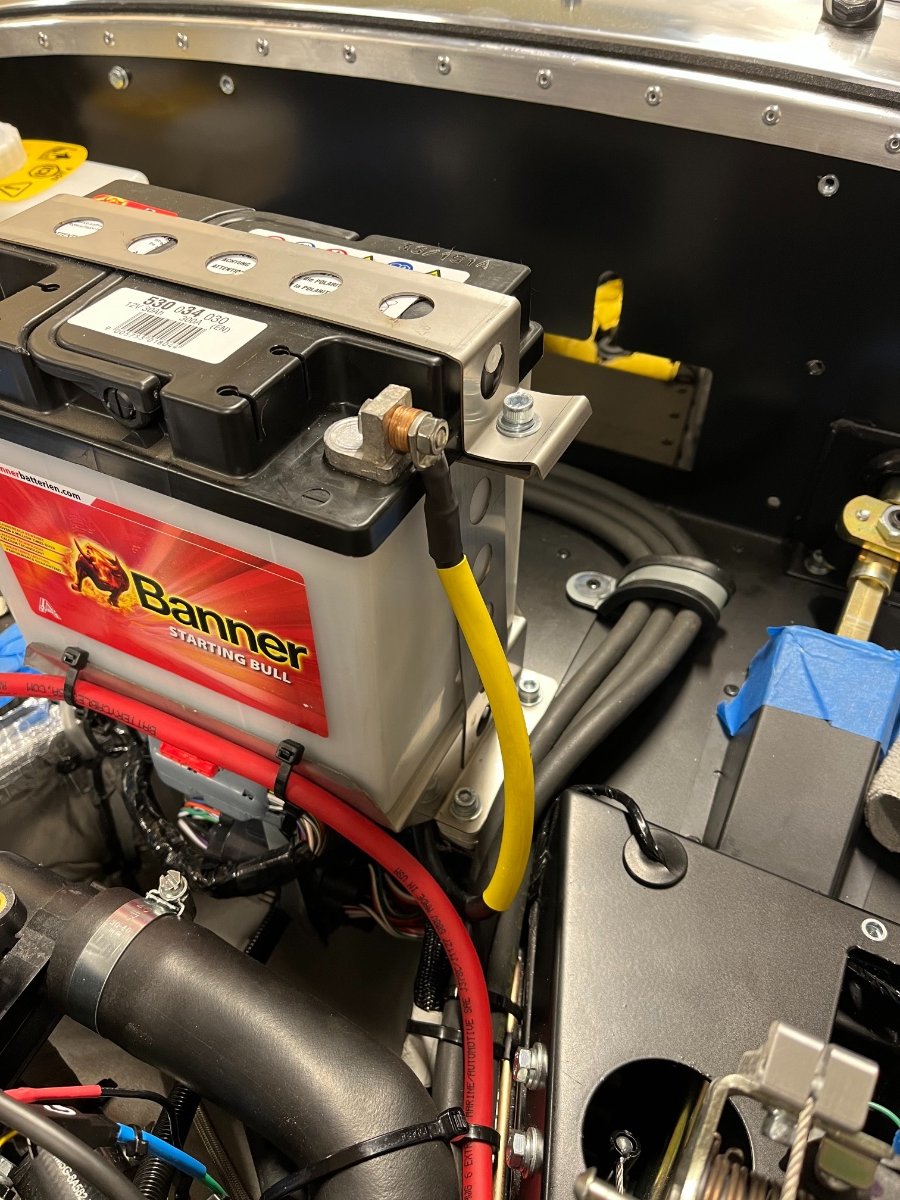
Battery Positive Cable As some things Caterham, this turned out to be a bigger and more time consuming topic than anticipated. When I first received the cable and tried to install it on the starter post I found the nut started too loose and seemed the wrong size. I bought and tried various size nuts only to conclude with help from Josh of RMC that the correct nut size is M8x1.25. Not being sure I had the correct one I bought a couple M8x1.25 ones and they looked and felt exactly the same as the one I had - loose along the exposed part of the thread. It seems that my starter post is somehow tapered towards the top. Pondering my options I decided to use the prevailing torque nut method, so I carefully and gradually deformed the nut into slightly oval by squeezing it in the workbench vise between opposite flats. The starter post seems to be coated with copper and I was aware that the deformed nut may damage the coating but decided this to be preferable over insufficient nut clamp load. I proceeded to tighten the nut by feel (don't know the torque spec) and it seems to work. Of course we will really find out when we go live and drive. Due to the tapered thread and deformed nut I decided to omit the lock washer. Finally, as the battery cable carries the highest current on the starter post I ended up placing its connector first (bottom) in the stack of connectors. The following pic was taken before that change. It shows the deformed nut and the post's copper coating. The next issue was the cable length. For unknown reason the cable I received, which is supposed to be standard for this kit, was 73" long. This is enough to wind it completely around the battery and still have extra length beyond reaching the terminal, as can be seen in the last pic of my previous main post. I measured the necessary length and came up with 32" (!), so I ordered a custom cable from BatteryCablesUSA. I specified 6 AWG as its corresponding OD was the closest larger than the original, the closest length above 32" which was 33", and the same ends -- M8 and M6. $12 and 2 days later I received exactly what I ordered. Before installing I tried to compare resistance between the two cables but my multi-tester does not have sufficient resolution -- both cables registered a fluctuating 0.1-0.3 Ohm. The nut on the starter post seemed to loosen and tighten OK the second time, and the starter post thread looks OK too. Last issue is tidy attachment of the positive and negative cable ends to the battery. I decided to run the cables vertically and use spacers to align the connectors properly. I considered on each side a solid brass cylindrical spacer with 0.25" ID, 0.5" OD and 0.25" length, or a stack of 6 copper washers (resulting in the same overall dimensions) which I have on hand. After some pondering and asking around I decided to go with the copper washer stacks. The assumption is that the copper washer interfaces cause a smaller conductivity loss vs. a solid copper spacer than the conductivity loss of brass vs. copper which is about 40%. I don't know the actual losses in the washer interfaces so this solution may need to be revised based on experience. Note that the terminals were connected for the photos one at a time... Next post(s) will cover the plenum, throttle cable (and pedal stop), and brief observations about hose and wire routing... Cheers!
-
Sure, no problem! To be honest, I don't know. This is my first encounter with this type of bracket (or with a catch bottle). The catch bottle, vent hose and bracket come together as a kit with the Caterham Duratec engine.
-
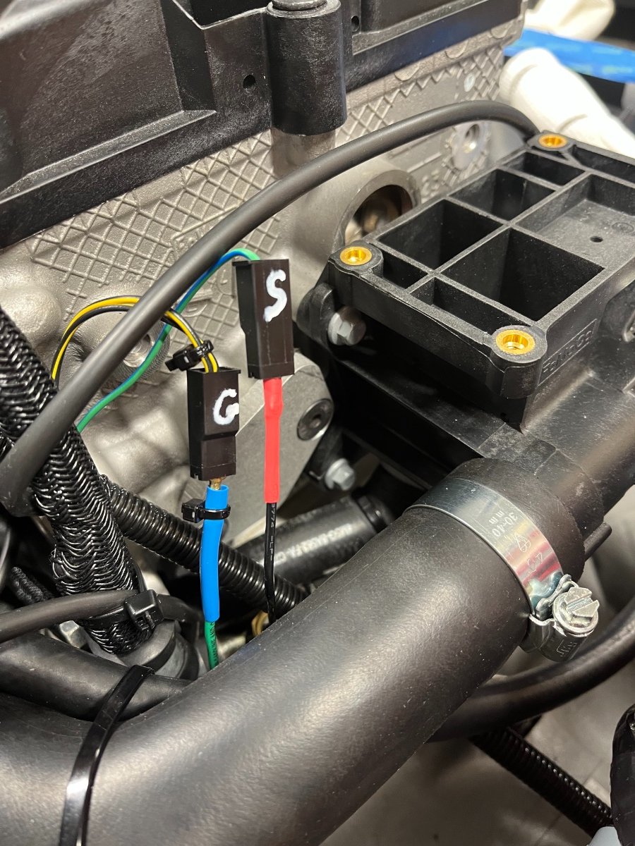
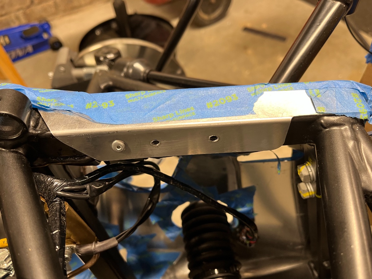
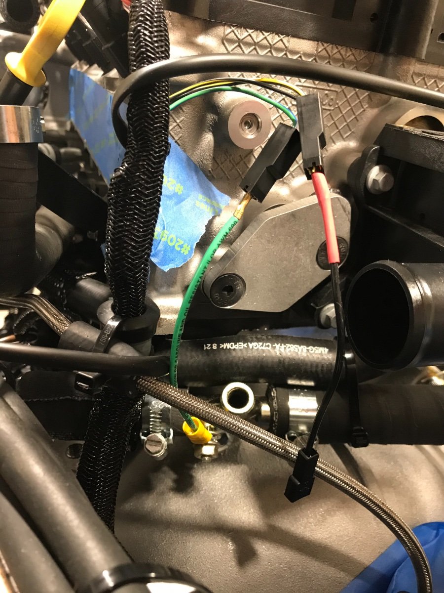
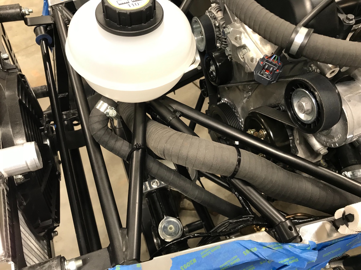
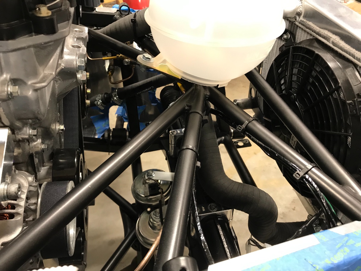
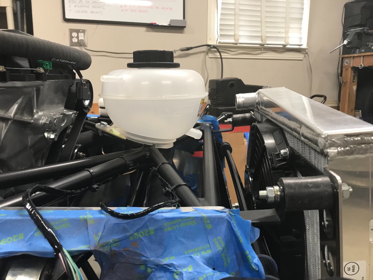
Hello All, Need to do some major catching up. We've made some progress over the last ~2 weeks but serious lag in documentation. Start with the shortages. Received the coolant temp sensor, catch bottle and battery positive cable. Let's cover them in that order. Coolant Temp Sensor Installed in submarine with Teflon tape and plugged in the extension wire. Tightened by feel. Tested for continuity between sensor body and ground post - checked OK. (sensor and ground post visible in pic just to the right of vertical black harness) Since my short extension wires for the temp sensor and ground post are not color coordinated with the original wires, marked S and G on the corresponding connectors and tied small zipties to both sides of the ground wire to prevent crossing them (agree, not super professional cosmetics but will work for now). Catch Bottle First had to disconnect upper radiator hose from radiator and re-route expansion tank hose under the top chassis tubes. Drilled hole in bottle for catch hose -- used 1" saw bit on drill press; worked perfectly. Drilled out one rivet to reuse the hole and drilled a new hole in the chassis for the bracket, both using my 30+ year old right angle drill adapter; also worked perfectly. (The rightmost hole below had the rivet, the middle one is new.) Needed to extend one of the slots in the bracket to use the existing hole in the chassis (Dremel tool). Need M4 or #6 washers to bridge these slots under rivet heads. Rearranged expansion tank hose to run under top chassis tubes (only to be re-routed again later...) and zipped the catch bottle vent hose to the chassis down tube: And here with radiator hose back in place (before more changes...). And overall view: Next post will recount the battery positive cable saga. Cheers!
-
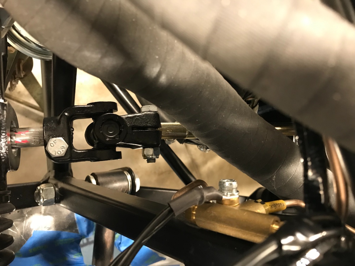
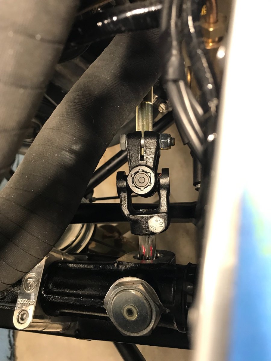
Hello All, Still awaiting the coolant tamp sensor, catch bottle and bracket, and the battery positive cable (all kit shortages), as well as the heater blanking plate as I have decided to delete the heater. In the meantime proceeded to install the steering column. Steering Column No major issues encountered. Here are the main steps: 1) Installed the U-joint on the pinion shaft with the input (column side) yoke vertical with the rack on center. I had the pinion center point marked when installing the outer tie rod ends. Verified by looking back in line just over the front discs and making sure my sight line meets the rear discs symmetrically LH vs. RH. All this because I want the slowest (most precise) steering rate on center. See enclosed math, courtesy of MathWorks (public info). 2) Inserted the lower steering column from the cockpit and then inserted the bottom splined end into the U-Joint. Had no issues engaging either U-joint spline. Greased both spline males beforehand with anti-corrosion grease. 3) Lubricated with lithium grease the lower portion of the upper steering column, inserted it from the cockpit guiding it from the dash end to pass through the lower bushing. Once it emerged from the "firewall" I mated it with the lower column (upper is female, lower is male). Again no issues. 4) Rotated the steering rack to minimize the U-joint angle and was able to reach very nearly on-axis alignment between the column and the pinion shaft, rendering step 1) pretty much moot (but this was not guaranteed). Had to loosen the rack clamps more (were not tight to start with) and wiggle it to get it to rotate. 5) Lubricated the inside and outside of the upper bushing with silicone grease (it is a split nylon bushing inside a rubber housing) and inserted it onto the upper steering column and pressed it into the dash hole. Used a suitable diameter socket to push on the outer rubber housing by hand. 6) Shifted the upper steering column axially so the cone for the steering boss is fully exposed with its largest diameter well proud of the dash; this can be further adjusted later if needed. 7) Aligned the flats of the steering column sections and installed the column clamp mid-length of the flat section. 8) Torqued steering rack clamp nuts to ~11 Nm and U-joint nuts to 32 Nm. Torqued steering column clamp bolts to 14 Nm, and tightened the "grub screw" and its lock nut by feel. Grub screw requires a 7/32" Allen key. 9) Pulled up the wiring harness near the master brake cylinder and zip-tied clear of the steering column. 10) Tweaked the routing and zip-tied x2 the lower radiator hose to chassis tubes to ensure clearance from U-Joint and brake lines. 11) Verified visually and by "steering" with the wing stays no interference with steering column anywhere. 12) Upon further visual inspection observed a gap between the shaft and its pedal box grommet on its bottom side. I wish I had taken a pic of the gap as found. I dozed the grommet with silicone spray from both sides and forced it up as much as it would go, using bare fingers and small pliers from the engine side and a padded craw bar from the inside. Gap virtually closed. Will keep an eye on it in case it opens up. Pulled up and re-tied the electrical harness outside the pedal box. The pic below is after the fix. Some Lessons Learned: - Leave steering rack clamp bolts really loose until U-joint and column installation to allow to rotate the rack easily. This in order to align the pinion angle with the column. - Hold off installing the lower radiator hose until after steering column installed, rack rotated, and rack and U-joint torqued. Currently planning next tasks. Investigating alternatives for front wing attachment to stays. Ordered coilover adjustment tool. May start next on the interior. Cannot button up the engine bay (plenum, throttle cable, airbox) without the catch bottle, temp sensor and battery cable. On the RH side do not want to install the collector/cat and then torque the header pipes before I'm done with the heater blanking plate and some of the interior. And I want to delay "cosmetics" (wings, lights) towards the end. Cheers!
-
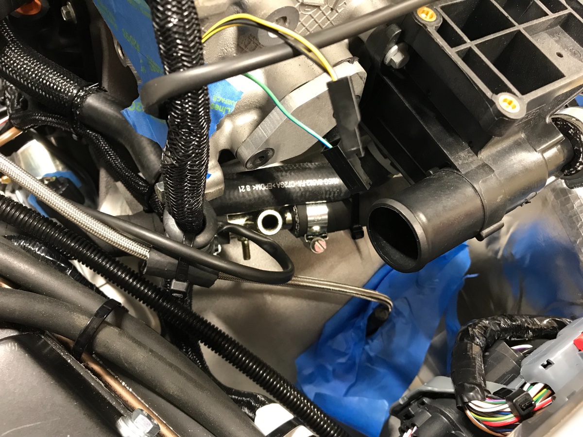
Small Plumbing and Wiring Tweaks While awaiting some parts (coolant temp sensor, catch bottle and bracket, heater delete blanking plate, battery positive cable) I made some small tweaks to the plumbing and wiring: PLUMBING: I decided to raise the T connector<-->expansion tank hose to minimize the syphon effect as well as make it a few inches shorter, and to change the T connector from 5/8" to 3/4" to reduce the restriction in the thermostat-modine-submarine-water rail path. I kept the straight coupler in the expansion tank hose at 5/8" since its flow rate is very low. (In the pics below the upper radiator hose is temporarily disconnected at the water rail and moved out of the way for a better view and to facilitate installation of the temp sensor.) WIRING: Made and added short extensions to the temp sensor and ground sub-loom to reach the submarine. Crimped a ring connector to the ground extension (green wire) to tighten directly onto the ground post, eliminating the screw-on tab. The temp sensor wire is awaiting the sensor... Next steps should be the catch bottle, heater blanking plate, battery cable (only at starter for now), steering shaft, and then the plenum, air box and throttle cable. Cheers!
-
More Plumbing -- Lower Radiator Hose Per advice from Josh R, I revised the routing of the lower radiator hose to avoid the hump over the chassis tube yet keep it away from the brake lines. This required shortening the hose in the section above the steering rack to pull it away from the brake lines. I used the cut (and sliced) portion as a cushion around the hose securing it to the chassis tube. View down from front of car View from left side View from right side into brake line junction area (note clearance). Cheers, Yoram
-
@IamScotticus, thanks a lot! Excellent idea. No, I am definitely not going to constrain the hoses too much. Sounds like zip-ties over the mesh should work well. Thanks again!
-
Thank you @KnifeySpoony! Good to know as I too swear by zip ties. Do you have zip ties in direct contact with/securing coolant hoses?
-
@MV8, thank you for this awesome information! Lots of excellent tips which I will keep in mind! Regarding zip-ties, are you saying that you have/had them in direct contact with coolant hoses with no issues? If so this is very encouraging!
-
Plumbing and Question Hello All, I've been playing some more with the cooling system plumbing. Proceeded to adapt and use the bits I have except bought two Gates fittings -- a 5/8" straight connector and a 5/8" T connector. Got all the hoses and the submarine plumbed (for now without the missing temp sensor or ground tab) except for the upper main hose and the thin hose from the water rail to the expansion tank. These will go in once I got any remaining kinks sorted. Most hoses needed cutting to length after quite a bit of planning and mock-ups of the routing. There are many potential interference or problem areas to avoid. Here are a few pics, and at the end I have a question for y'all. Lower main and expansion tank hoses. Note the lower hose climbing over the chassis tube and back down to keep it away from the brake lines. That point is higher than either inlet or outlet but a bit below the inlet and outlet of the upper main hose. Will this cause an issue with bleeding the system? If anyone has any observations about this please speak up! Edit: ** Please see update in a separate post dated 4/4/23 ** (But please hold off on the zip-ties till the end...) Same hoses, different view. The T (at lower right): Lower "Caterham" hose comes from the expansion tank, upper "Caterham" hose goes to the thermostat (right above the main lower hose connection), and the upper right one goes down to the modine. I decided to buy a Gates T (at local O'Reilly's) because of their high temp rating (up to 480F) , and 5/8" instead of 3/4" because the supplied 3/4" T was very tough to insert (the submarine and expansion tank ports are 5/8" male). Next you are looking at the left rear corner of the engine block. The bell housing is masked so nothing falls in through the clutch hose hole.... The submarine can be seen in the middle, viewed from above, with the hole (tube with internal thread) for the temp sensor and the little threaded post for the ground tab. The hose attached to the left side of the submarine (barely visible) connects to the other modine port, and the one attached to right side is the J-hose. You can see its other end attached to the water rail at the very right edge of the pic. This is a better view of the famous cut-off J-hose connecting from the water rail to the submarine (itself not visible from here). Submarine closeup. It is "floating" on the hoses, not touching the bell housing. * * * * * And now to my question! Does anyone have good experience with some type of high temp zip ties to keep the coolant hoses from vibrating and chafing? (not instead of hose clamps...) I installed temporarily some standard zip ties just to test and confirm where I want them. I am well aware that standard nylon zip ties are limited to around 185F and even the Hellermann-Tyton high-temp ones are rated up to 257F, which may be marginal over time, but looks like my best option right now. I love zip ties because in addition to being easy to use they don't mar the finish of chassis tubes. That's why I'm reluctant to use stainless steel zip ties (although I have no experience with them) as I'm concerned they will dig into the coating. And I don't want to drill to install Adel clamps. I'll gladly use an Adel clamp where I can readily attach it to an existing bolt or hole but that's not where my hoses want to be secured down. What do you guys think? Thanks and cheers!
-
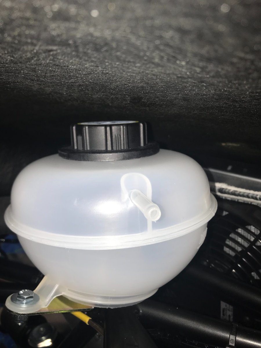
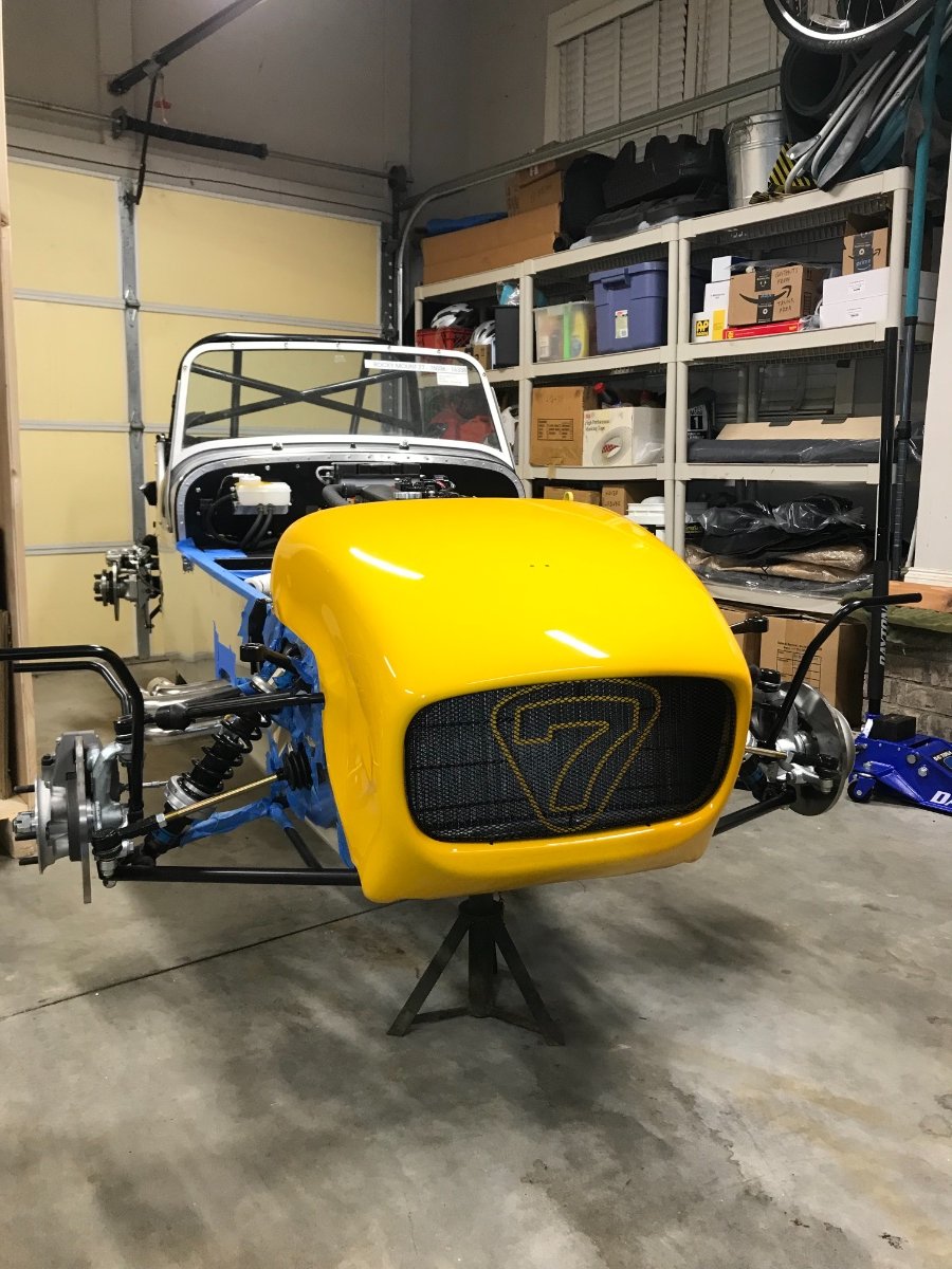
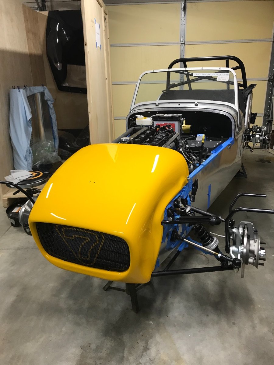
Trying On Nose Cone! Today I temporarily installed the nose cone -- just placed on without securing in position. The excuse was to examine the gap above the expansion tank cap. It does not seem to touch when I push down the cone into what seems like home position but it's hard to know. Will have to wait until I can perform a full test with the bonnet and nose cone both in place and secured down. But it was fun seeing it for the first time on the car.... Cheers!
-
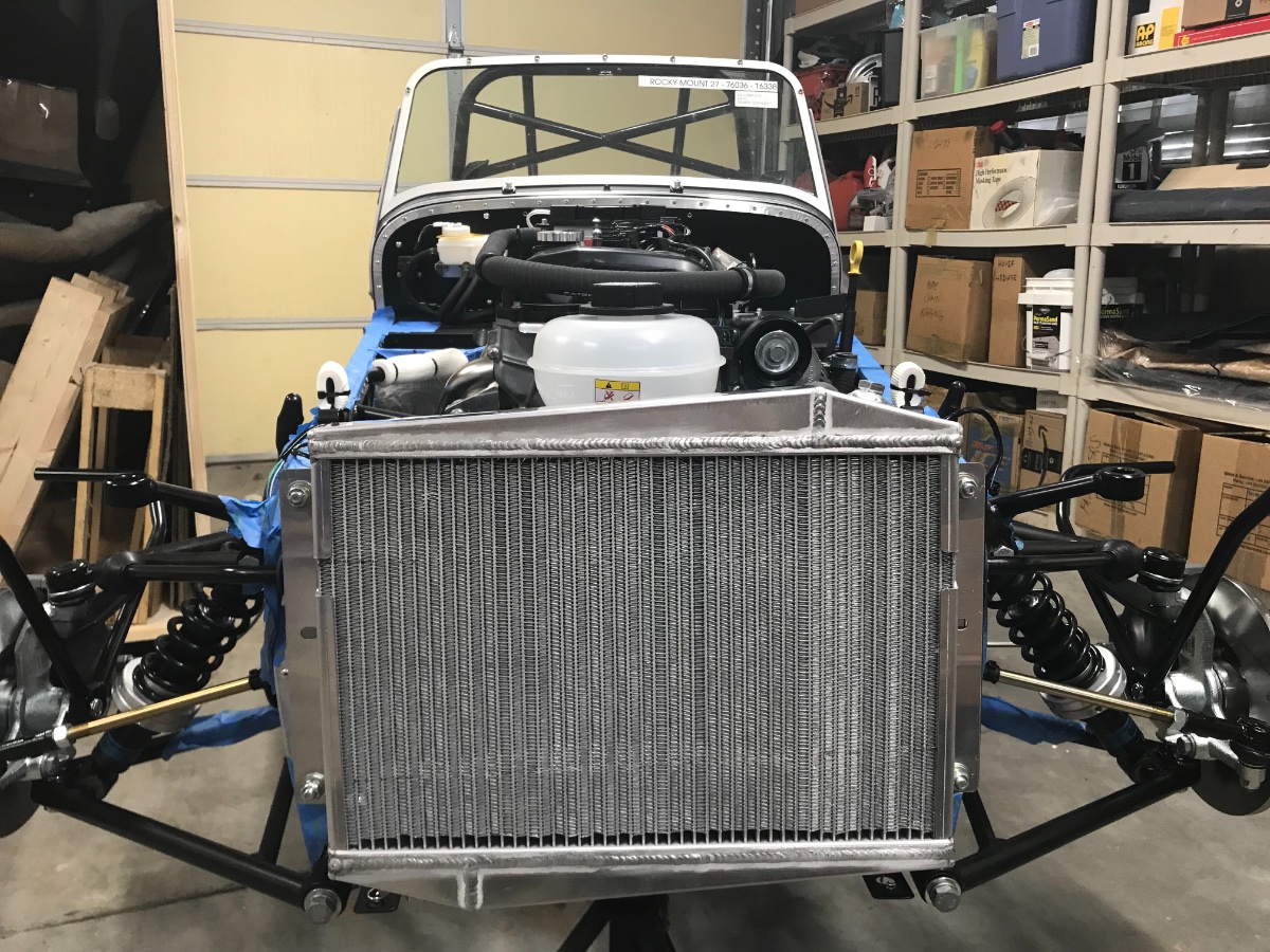
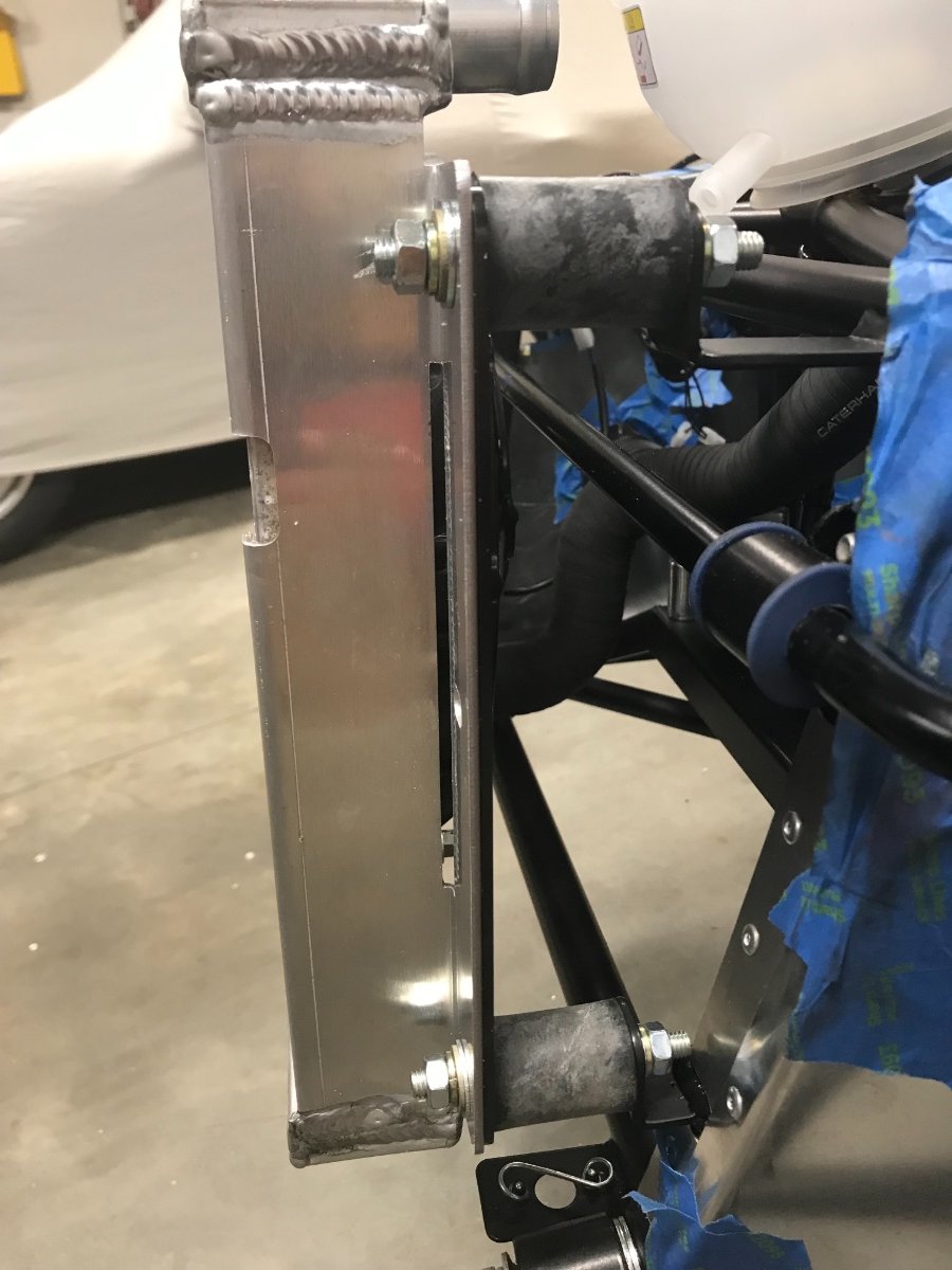
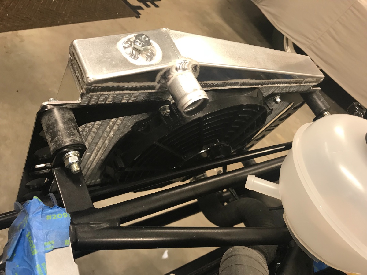
Cooling system start My plan is to delete the heater/blower unit and install a blanking plate on the cowl. Received a plumbing schematic from Josh R. for the heater delete configuration. Radiator and fan: Installed radiator and fan with some washer tweaks. Found no 5/16" lock washers in my kit for the radiator mounts. Need (2) per mount, one on each side. Bought locally and installed (8) Grade 8 lock washers. Also installed (4) additional Grade 8 flat washers on the outside between the lock washer and the supplied oversize washer to reinforce over the radiator oval holes. After initial tightening it seemed that the radiator is not quite horizontal but rather drooping a bit to the right -- tolerance and clearance stack-ups. So I loosened all 8 nuts and biased the radiator up on the right and down on the left as far as it would go while retightening. I didn't perform verification measurements but visually now it looks better. Tightened by feel. You got to watch not to twist the mount rubber too much while tightening; there is no good way to provide counter torque which does not torque the rubber. Lower main hose: Routed the hose over an upper chassis tube to prevent contact with the brake lines. Edit: ** Please see update in a separate post dated 4/4/23 ** Expansion tank: Expansion tank bracket ear must point backwards for the tank to be close to horizontal. Bent the ear up a bit by hand to get closer to horizontal. Looking at the height of the tank cap vs. top of engine and radiator and reviewing Chris Collins' blog I am aware that there may be a clearance issue under the nose cone. This remains to be investigated. (also see first pic for front view of the tank) Concern: Most male connections are 19mm OD, except three (submarine and expansion tank) which are 16mm. Hoses are 16mm ID. They do go on with some silicone spray but look quite bulged/stretched. Not quite happy with this but seems to be the Caterham way... Would appreciate any observations on this. Also raised the question to Denver. Open Issues: 1. Unable to find the temp sensor and ground tab in the kit to thread into the submarine. Notified Denver. 2. Looks like will need to order another J-hose or L-hose for the modine connection and a few couplers to execute the plumbing scheme. Will report exactly what I ended up doing. Cheers!
-
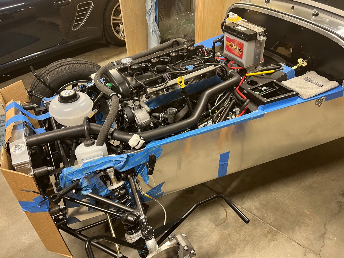
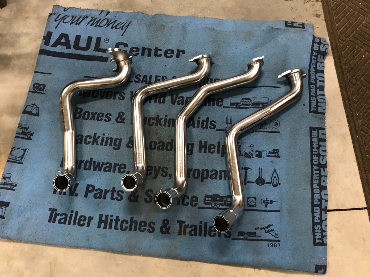
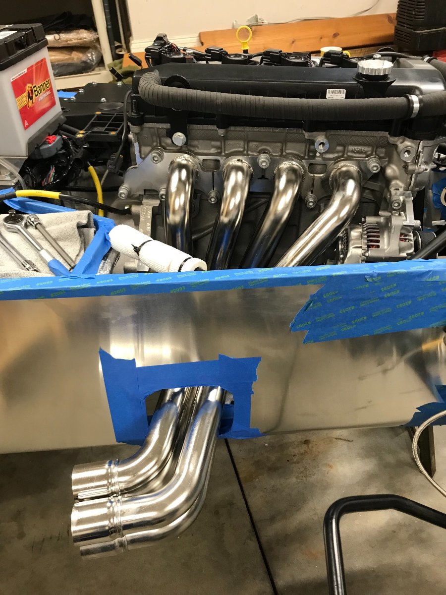
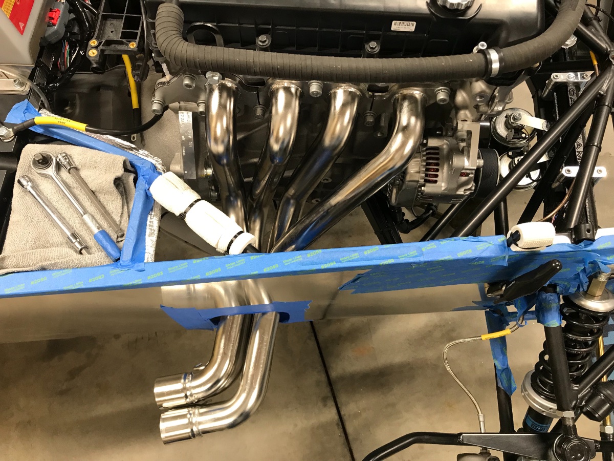
Hello All, Some progress over the last week on the exhaust and cooling systems and some open issues... Exhaust start Some notes: Protected body opening with masking tape. Removed stickers off pipes with Goo Gone. Removed protective masking tape from ports and cleaned sealing surfaces with Goo Gone and microfiber cloth. Figured positions by laying all 4 pipes on a mat, examining tube and flange shapes and arranging in order. Installed the pipes in order from front to rear, passing the collector/cat ends through the body opening from the inside. No difficulties. Left the flange bolts finger tight. Will tighten once collector/cat installed, much later. Oyyy, it now looks like half a street rod... Cheers!
-
Thanks! May need to succumb to Amazon again. Will check our local hardware store first, you never know what you might find there.
-
Yes. I'm good - wasn't a big deal doing the gravity feed with a small diameter hose. I do need to find that 2" blank grommet. Any ideas? Best I found was $10 on Amazon -- I refuse...
-
Yes, I saw the hole in the footwell skin (no grommet - will get one) but didn't want to injure the heat shield.