DanM
-
Posts
348 -
Joined
-
Last visited
Content Type
Profiles
Forums
Store
Articles
Gallery
Events
Library
Everything posted by DanM
-
Sorry for the delay I have been away. I haven't weighed it but the research I did suggests that it's roughly 65–68 lbs for the differential assembly itself (housing + Torsen internals, no axles or driveshaft).
-
Now that the car has met the Ontario safety standards, I had everything I needed to get it registered with the Service Ontario (The organization that issues registrations, plate, licenses, etc.). Registration merely means that the Ontario government officially acknowledges that the car exists, it is registered in their systems as being an Ontario car and I am the owner. So, how do you get a kit car registered in Ontario? Good Question... On their website there are plenty of instructions on how to register a car, but there is nothing related to registering a kit. Thankfully, with the help of my AI app, I was able to cobble together a number of old blogs and articles from hotrod community forums and piece together a list of things that I think I needed. I then went through all my paperwork to build a folder of information to take with me to the Service Centre. Here's what I pulled together in a folder: 1. Affidavit of Vehicle Ownership and Assembly (Notarized) 2. Starter Kit Order details 3. Import approval and customs clearance paperwork 4. Bill of Sale for the Starter kit, donor car and any other major components purchased. 5. Ownership paperwork for the donor vehicle 6. Safety Inspection Certificate 7. Selection of build photos (Including VIN Plate) Here's what my Affidavit looked like. Once my pack was together I booked an appointment to go and register at Service Ontario, to my surprise the earliest appointment I could find 30th October!!! Still, I figured I wouldn't be driving it this fall and knew that the Safety was valid for a while so I didn't think anymore about it. That is until my parents in the UK started asking questions that started to put doubt in my mind. To put my mind at ease, I went back on the Ministry site.... So, it turns out that you only need a safety standard inspection and certificate if you are: registering a rebuilt vehicle transferring a used vehicle to a new owner (unless the new owner is your spouse) registering a vehicle in Ontario that was bought in or came from another province, territory or country changing the status of a vehicle from unfit to fit If the car is registered the safety only has to be repeated again when you sell it (GREAT) - Otherwise it is only valid for 36 days - SHIT!! 😬 The car was safetied on Friday 12th September and it was now Sunday 5th October. If I waited until my appointment then the certificate would be invalid. I had to present it for registration ASAP in case I needed additional information. Thankfully my work is flexible, so I took the next day off, drove the kids to school and then went to the nearest Service Ontario location I could find. I arrived there at opening time 09:00, and the queue was already out of the the door! After queuing for at least 1.5 hours it was my turn at the counter. The lady was really patient, but had no idea how to register a kit car, she spent most of the time on the telephone to the support centre, clarifying information and scanning/faxing documents through to them. I think it was 11:45 when she finally said its all good, but we just need the supplier and manufacturers address on the affidavit (it wasn't there on my first version). Once I had that she could run it through the system. Frustrating and so close, but no big deal, I went home and updated the affidavit, called through to the instant online Notary service and got myself a new affidavit within the hour. Thankfully, when I came back she called me to the front of the queue and I had my registration document within minutes!! Now everything is officially legit!! Insurance and license plates are next.
-
Thanks @panamericano, It's a huge relief!
-
So, with the little bits buttoned up and the car tuned, I was now ready for my safety Inspection. The question was, where would I take it? Over the last couple of years of selling donor car parts and trading tools, jacks and other garage bits, I had gathered a list of potential garages that could help me through the inspection. Context: In Ontario, there aren't specialist government run test centres, I think any garage that had the right equipment, compliance paperwork and trained staff could apply to be licensed to conduct them. This meant that I had at least 10-20 inspection places within a 15 minutes drive. The challenge I had was finding a shop that had experience working with kit cars or custom cars, could understand the rules and interpret them sensibly. By late last year I had whittled down the list to a couple and started discussions with them. By the end of August this year when I went to book, I found out the rules had changed.... Well, actually the rules hadn't changed but the process had. The Ontario government has modernized and digitized the process. All garages who wanted to continue offering the service were now issued with a Government tablet and the tester was required to log on to a live online inspection session with the Ministry. The tablet software would guide them through the steps, starting with a Vin vs ECU check, and then moving through each test point, requesting photographs to be uploaded and measurements to be taken and entered to the system. If anything was flagged as irregular the garage would receive a call from the ministry during the live test. Lastly the certificate was no longer issued by the garage on behalf of the ministry, the ministry now issued the certificate electronically. The impact to me was that the garages I had been talking to both said they wouldn't do it anymore. One hadn't registered for the system and the other one was not prepared to dedicate the time needed to go through every check point.......I guess that's why the new process was introduced....to make people do it properly. Lol At that point I rang around some of the garage/shops that had been helpful during the build, to see if they had any ideas. Thankfully one of them was on the new system and was prepared to put me through the test time and materials. So with that sorted, it was time to borrow another tow vehicle, rent a trailer and head out to the shop that had done my engine work three years earlier. It was a weird feeling that the first person ever to get the car into third gear on the road was the tester, but I was happy to get the ball rolling! BTW the sun visor didn't move an inch!! 😁 I sat outside on a camping chair for about 1.5 hours while they went through the online session. It was a gorgeous Friday afternoon, no work, just the sound of tinkering in the garage and dozing off in the sun. Eventually the technician told me everything was complete and he was just awaiting the final results from the the ministry.....PASSED!!! For those of you that have been through this, can understand the relief after so much time, blood, sweat and cursing was insane! Awesome!!
-
Thanks @Austin David. It is a newer intake and a full rebuild and clean. Cylinders were honed and block was levelled. I think they made about 100 wheel hp from factory, but I happy to be corrected. re: the exhaust it does have a built in cat. Definitely wouldn’t have passed without it. Lol
-
So at this point I was very close to getting a safety inspection. While I was trying to find someone who would do it for me (not easy), I took the day off and trailered it to a dyno and got the engine tuned up. As you may remember I rebuilt the 1.6 and so wanted to get it set up nicely before using it. I wasn't looking for anything fancy just wanted to get it running well for the road. The tuner (BRTuning) was located at the Calabogie race track, just over a hour West of Ottawa so I needed to rent a van and a trailer to get it there. My Brother-in-Law Chris came along for the ride which was helpful as I needed to jack the ramps up on either side so the exhaust pipe didn't catch on the transporter. It also took a while to fit the straps over the front wheels as the front wing clearance was tight. We got it inside and on the dyno just before the rain started! After a brief chat, Brett got to work. We were amazed at how fast he got in the zone and worked his way around the Megasquirt. Very happy with the final result.
-
A couple more minor jobs ticked off the list. First, I wasn't happy with the fit of the crash pad trim where it meets the door sills. There is a gap between the dash and the sill padding that makes it look unfinished. I had a little piece of carbon effect vinyl left over from the gauge plate so I thought i'd use that to tidy it up. First I made a small template for each side out of cardboard. Then, I used the template to cut the vinyl. I think it looks much tidier now there is no green showing between the dash and the padding. Once that was buttoned up I turned my attention to the stone guards. I remembered reading a thread about some of the difficulties people had had keeping the rubber trim secured to the edge of the guards during installation. again, I forgot to take photos but my approach was to use heavy duty vapour barrier sealing tape (Tuck Tape). This stuff sticks to everything! Offered up the rubber strip to the sides of the guards, using tuck tape to secure the trim as it contoured around. This way everything was secured before I positioned the guards on the car. To attach the guards I taped them in position and drilled the pilot holes using Clecos to hold it in place while I riveted.
-
Thanks @jbcollier, I'll certainly keep that in mind!
-
Unfortunately, you do have to have a bumper in Canada if its being registered as a new vehicle, especially Ontario. They will not pass you without it. If it was an imported car already built and over a certain age it may have got by. They have also digitized the Inspection process in Ontario this year, to stop dodgy certifications and "back handers". Any garage that now performs a safety is issued a tablet and the safety is done live online. The tablet guides them through step by step and they take photos as they go through the checks. If something is flagged or anything not quite right then the ministry will call the garage immediately and challenge it. at the end of the live session, the ministry issue the certificate not the garage! This came into effect this spring.
-
The bumper was something that had been stressing me out for quite a while. Mainly 'cos of the aesthetics of them. The Ontario Inspection standards rule: "Bumpers are required on the front and rear of passenger cars, mini-vans or SUVs as well as on the front of trucks. Rear bumpers are required if originally equipped on a truck, unless removed to facilitate the installation of other equipment." You will fail the Safety inspection if the bumpers are: a) - missing, modified, inferior to original OEM design (width, size, structural integrity) or incorrect for the vehicle. - broken, misaligned, loose or missing structure, supporting structure, or fasteners b) -collapsed, inoperative - any section has exposed sharp edge, is torn or protrudes in a manner that could be hazardous to the driver, a passenger, pedestrian or cyclist. -any perforation due to corrosion So I know I need them, I know they must be secure and safe, but I have no idea what "inferior to original OEM design means in terms of specification. Some say it is 5 mph without causing a system failure, some 10mph, but nothing is written down anywhere. With that in mind I decided to make something that looked safe and secure, with the materials I had at hand.... Some wood and some lengths of steel angle bar left over from my lift delivery. I started by cutting up some of the bar and drilled some holes to make some brackets that could be bolted to the spare wheel bracket. Then I positioned them together and welded them up with my stick welder. I then welded some longer lengths together with another piece of metal welded at the join to keep it all together. Finally I bolted some pieces of wood to the metal to give it s soft surface and sanded down all the edges so they were not sharp. To make it more cosmetically pleasing I painted it black with...you guessed it, Rustoleum All-in-one. Looks quite presentable and feels very secure. Not that it will make any difference at all if a Ford F150 rolls over me! 🤷♂️
-
Thanks for the info, unfortunately they are not present in Canada.
-
I just looked for insurance for my recent build project, still no luck but here's my feedback. Hagerty - Felt a bit tricked - I filled out their online form to check premium options with and without autocross insurance - they came out the same so I pressed submit. I then got a call - because I checked both boxes (out of curiosity) they would give me racing insurance only but not road insurance. I now have to wait a year to reapply. Vintageautoinsurance.ca - Will only insure kits if it is a replica of a pre-1950s car. (He said the poorly assembled and high powered Cobra's were the main reason) Zehr - Would insure me, but need a 6 year no claim. I am 50 years old, lived in Canada 14 years and in that time have had one $0 minor shunt last year in the snow. Now I cant get insured on the Westfield for another 4 years. Facilities quoted me $1,000,000 liability coverage for $2630, Collision and Comprehensive with $1,000 deductible would increase that to $4080 Still looking if anyone has any ideas....
-
At this point in the build I was starting to think about the specific details I needed to pass the Ontario safety inspection. Specifically, Sun Visor, Side Lights and Bumper. Lets start with the Visor, the Ontario rules state: From this I guessed that as long as I had something on the drivers side that was adjustable yet secure I would meet the criteria. With the screen being so small and the frame being so thin, I needed something fairly small and delicate. After over thinking it for a few days I decided to for the simplest solution I can find. I went to the Dollarstore and picked up a plastic cutting board, then cut a 3 inch section down the length of it and used some tape and scissors to the make a radius on the corners. Then, I stuck some Velcro vertically on the back and horizontally on the frame. Covered the Velcro with painters tape and sprayed it black with the old faithful Rustoleum All-in-One. Lovely Jubbly! Next were the side lights. Because I had incorrectly installed the supplied clear side lights on the body, I needed to buy some to put on the wings. I bought some from the local Auto Parts Store, and installed them as far forward on the wings as I could whilst still leaving enough wing material to hold them securely. Then, I ran the wires and spliced them into the indicator/DRL harness on the car. I zip tied the flexible brake hose at the same time. Next up, the bumper. 😬
-
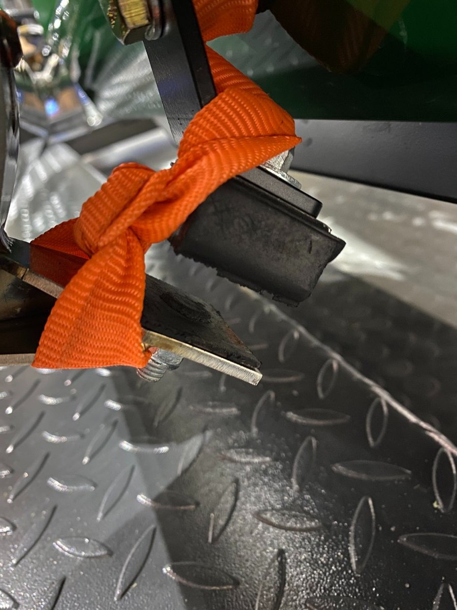
Next up was my harnesses. Again, I don't have photos of bolting them in so here are some after photos. I bought Schroth Westfield II ASM harnesses. At this point I didn't want to cut the excess belt so I just tucked it behind the seat. They are still like that so if someone has a neat way of folding them I'd love the hear about it.
-
Somewhere amongst all this activity, I fitted the tunnel carpet and side panels. I must have been in a rush or distracted 'cos I forgot to take any photos...sorry about that. The only thing I can say is Velcro....and lots of it! I think I may have over done it 'cos when I was done I needed to buy more for other area. 😁 With everything very securely in place, I turned my attention to the gear stick gaiter. I think I must have been a bit over zealous with the tin snips 'cos I seemed to have taken out a bit too material than I needed for gear stick clearance. With the hole so big the supplied gaiter just didn't fit at all. After looking around on amazon and eBay for gaiter and surround kits, I decided to "make" my own. I remember changing the gaiter on my Toyota Matrix a year ago and noticing that inside it there was a soft structural felt. I still had the old gaiter so I took the felt out and set it aside. Then, I measured the hole and went down to the local salvage yard to see if I could find a larger gaiter from a wrecked car. An easy task you may think, but with over 90% of cars in the yard being automatics it was slim pickings. Eventually I found a Gen 3 Subaru Impreza manual and the gaiter was perfect. With all the parts now in hand, I bought some shoe repair glue and I was ready to go...First I made a stencil for the base. Then I cut up the felt and stuck it to the template to make the new base. Next, I glued and clamped the gaiter to each side of the base, waiting for it to dry completely before moving on the the next side. Once it was completely glued I attached Velcro to the base and positioned it in place around the gear stick. IMHO, there is a bit too much fabric, so I'll likely tailor it in a future project, but for now its much nicer (and cheaper) than anything I could find on line.
-
Next up, the wipers. Straight forward as it comes, although I was a bit nervous clicking them together. I honestly thought I would break them with my ham hands. Then after trying them out and testing the spray, I realised that I hadn't sealed the fillet so washer fluid dripped down behind it. So, with everything in place I tapped up the fillet and applied cleat marine sealant.
-
My vision for wheel style varied wildly during my build. I like many different types of style but in my mind, I wanted something a bit rough looking with spokes, sort of a modern aged look. With cash a bit tight i was constantly on Facebook marketplace hoping to find something that fit the bill. Eventually these came up. They are OEM from a 1997 Acura (Honda) Integra LS, 14 x 5 1/2 with an offset off 45mm. I'd need to get hub centric rings and probably some spacers (in the future), but for now this is what I'm going with. I got my hub centric rings from circuit size 56.1 (Honda) to 54.1 (Mazda). For tires I went with Falken Azenis 195/60/R14 front and back.
-
Wanting something completely different to focus on I installed the floor carpets and test fitted the seats to make sure the holes still lined up from my initial measurements. I also started to play around with the gauge plate that I'd made. My OCD was getting the better of me and although the carbon effect wrap was ok, the fit just wasn't as I wanted it. In the corners you could see the folds and imperfections, so something had to be done. 🤪 I experimented with a bunch of different materials and templates with limited success. Eventually, I did what I should have at the start and bought myself a small sheet of carbon fiber. Cut out the holes with a hole drill bit (Just smaller than needed), then smoothed it out with a Dremel. After a bit of shaping in the corners it came out really nice! To keep it all secure I JB Welded some nuts to the back of the dash. Tidy
-
Back on the blog with a lot of catching up to do. Thanks to everyone who reached out with personal messages to help me get going again after some time away. I have actually made slow and steady progress since my last post so this will be me documenting what I have done rather than what I am doing! Let's get to it.... First, I'll start with the biggest time consuming, frustrating and demoralizing part of the last year or so...my mystery oil leak that showed up after the first start back in August 2023. This was the single biggest frustration and cause of stress for me. If you recall the leak was somewhere behind the belts and covers and so I couldn't easily determine where it came from, was it the crank seal? was it the oil pan? was it the cam seals? or was it something else? With limited available time in the garage it was a very time-consuming process, removing the covers, belts, cogs, etc. inspecting, buying new parts (Seals, gaskets) making a fix then re-assembly and test. After a fix it would run ok for 5 mins but then once I turned it off it would drip. It doesn't seem like much but when you're stretched for time and cash and trying to problem solve on a budget, hedging your bets on a solution, the months go past quickly, the family tolerance for the build goes down and the stress levels rise! 😧 In addition, knowing that a used engine could be bought cheaper than some new parts, the battle between my head and my heart raged constantly, especially after all the time and money I had put into rebuilding the 1.6. Every time I put in a new seal and saw the leak persist, I'd question if I installed it correctly, leading to the purchase of another seal from Mazda. In total, I replaced all the front cam seals once and the main front seal at least 5 times. I even removed the removed the oil pan, cleaned it up and resealed it. Eventually, I had a final choice to make. Do I buy a new engine, or do I buy a new Boundary oil pump, both worked out to be a similar price. My head was telling me to get an engine (more power, better reliability, more aftermarket part options); my heart was telling me I had too much invested in this one to give up. I went with my heart and gambled on the pump. I installed it as soon as I could, and once again everything had to come apart. I reluctantly fired it up and watched it run for 5 mins. Once it reached temperature, I turned it off and waited for the drip......Nothing!! 😂😂😂😂 Finally, I could move on. 🙌
-
@IamScotticus it is a PEAK 407P. https://babco.ca/products/peak-407-p I have low ceilings so I needed something low(ish) to fit without too much garage door modification. In the end I had to remove the door motor and chain rail, but I'm OK with that. I cant raise it all the way, but its definitely high enough to get really good access underneath my family cars. The Westfield is on there temporarily while I fix the oil leak (Yes, its still there). It needs a long shallow ramp otherwise the exhaust and oil sump interfere (ask me how I know! lol)

-
Another fun little project was the courtesy light. I wanted to conceal it in my 12v socket surround so I bought flat wire LEDs that could lay under the carpets and behind the plastic cover. After installing the seat back carpet I cut the socket holes and ran the cables. Then I put the socket surround in the vise and drilled a small hole for the LED to shine through. Done! After testing it had a nice mellow glow, I like it a lot, but think I may need another one on the top or on the sides to get a bit more coverage.
-
So after a very busy summer I'm finally back with some updates. In general, I didn't get to spend as much time in the garage as I'd hoped, partly cos of the heat and partly cos of work and partly cos I was tired of the build. I think it was mid to end of June before I went back into the garage and that was to install the four post lift that I bought at the end of the winter. I bought it more for my other car than the Westfield, but its definitely useful none the less. With the lift installed I wanted to get away from wiring and do something else to get my enthusiasm back. I decided to paly with the dash. The first order of business was to trim the centre section so that it hung down properly. I used my dremel to cut it down from this: To this: Then I assembled it to see what I needed to do next. I had to hack away quite a lot of the upper steering wheel cowl to fit it in place. and then I could test fit the gauge cluster in place. With very little structure to hold everything together I now had to come up with a plan to hold everything in place and still make it easy to remove the dash without taking the cluster with it.
-
@Austin David I'm not looking to do anything too adventurous. I just want my 3 savage (EAO) switches to illuminate 50% when the headlights are on and brighter when they are active. I'll definitely share how I manage to do it!
-
Now that the front end of the car is close to done up I am turning my attention back inside, specifically the switch illumination. I am trying to wire and program a small Arduino unit to control the levels of switch illumination of the Horn, Demister and Hazard savage switches (EAO) under various configurations. I'm still figuring stuff out as I go, but here's where I am so far. I have collected the following items for the set up: Arduino Nano Every and screw connection block. 12V to 5V Power converter/regulator Project Box Left over wires and connectors from the MX5 Miata loom Connected together it looks something like this: In summary, the green wires will go back to the relays and the long wires will go to the switches. I have recycled a MX5 Miata connector block so I can remove the Arduino from the car with the dash if necessary. The Arduino pinout are: Next step will be to organize the car end of this circuit.
-
Good grief, I cant believe that another month has passed!! To be honest, a lot of it has been spent faffing around with my 3D printer trying to print with ABS. I successfully managed to print the EAO switch connectors, but everything else I tried ended up in the bin. 😞 I also spent many hours scratching my head over the cycle wings, especially as the brackets seemed out of shape. After many attempts using weird and wacky home made measuring devices I settled on a piece of broken driveway marker pole (that had been chewed up by my snow blower during the winter) and the level on my phone to get things symmetrical. I then used some strong vapour barrier tape to hold them in place while I marked the brackets for drilling. Once the initial holes were drilled I held the wings in place with Clecos and painters tape while fettling them into final position. To secure the wings I drilled oversized holes in the fiberglass and stuck foam on the brackets to hopefully reduce the chance of cracking. Only time will tell if it is good enough!! 🤞