TEM
-
Posts
222 -
Joined
-
Last visited
Content Type
Profiles
Forums
Store
Articles
Gallery
Events
Library
Everything posted by TEM
-
Maybe I lost you somewhere. Your comment "I suggest rotating the crank key slot to the top center (0 degrees/tdc for #1)" I assumed you wanted me to set the engine to TDC on #1. Reading it again, are you are saying that setting the crank key-way to the 12:00 position it equal to TDC?
-
I definitely have room for the camera. The issue with these cheap cameras is quality of picture. I tried to us it to inspect my gas tank. Utterly useless. My first guess was either a damaged bearing or a weak release arm that may be bending when depressing the clutch - could still be.
-
I have seen them col;lapse but not internal unwinding. My new hoses have a removable steel wire that prevents them from collapsing under suction or sharp bends.
-
I tried the 3/4" when I first rebuilt the masters, I don't recommend it. All of my cars are standard transmission, this one with 3/4" clutch master was extremely heavy. Slave is 3/4". Rod length should not make a difference as long as you can screw the dome nut far enough to set the adjustment. It can only push as far as the slave moves. Mine is long enough that you can't remove it without first removing the slave cylinder. I pulled the boot off the clutch release arm and was able to see inside to a limited degree. The fork looks to be straight, the pivot is in good condition and the throwout bearing spins freely. Is it possible to put in a pressure plate that requires more throw than our slaves cylinders put out? Tomorrow I'll make up a length of hard pipe to see if that improves the shifting.
-
Now that this new to me car is finally running after decades of slumber, I'm faced with a clutch issue. I have trouble getting the car into gear with the engine running. I have rebuilt the slave cylinder and the master is a new 5/8" Girling. The system has been bled and the clutch has been adjusted per the manual. I just re-bled and re-adjusted the clutch with no improvement. Maybe this is why the previous owner had swapped the brake and clutch master cylinders. I'm looking for suggestions that don't involve pulling the engine. I know this is a probability but would like to exhaust all other ideas first. There is a red tube that connects the master to the slave. Is this original? My Esprit had a similar clutch hose and when the engine would get warm, the hose would expand and it would be difficult to get into gear and grind gears when moving. The solution was to change this tubing with a SS hose.
-
My head. i don't know what the AB stands for.

-
Since I rebuilt the mater and slave, before re-installing the slave I raised the slave above the master and oriented the bleeder upwards. I clamped the piston so it wouldn't shoot across the garage and bled as usual. I have not had any issues with this process on my Elan. As for cooling, after I resolved the "blocking" gasket I moved to carb tuning which meant removing the nose cone and tuning off the fan. I did periodically blip the throttle during the process but the car did eventually over heat. This time everything was hot including the radiator. So a bigger fan may help. But first I want to get everything else working correctly and see how the car behaves on the road.
-
You bring up a good point. I have a 109E block but what I believe is a 116E head (based on the casting number). And who knows what cam is in there. But, where I have it now (center of the marking) is too much advance so either I don't have a 116E head or the cam is different than original. I'm not sure why they would put a 166E head on a 109E block. My understanding is that all the goodness of the 116E is in the block (5 bearings, longer stroke, etc.). Maybe they had head damage and just put on what they could find.
-
That statement is from the 109E portion of the manual.
-
The new pulley has part number 681F 6312 cast onto the back face which others indicate is the original part number. The Manual has the statement Does this mean that I need to align the notch on the pulley to 1/8" before the pointer on the case? If so, this would make sense and would reduce the initial timing.
-
Timing is predicated on knowing where TDC is on the pulley. I'll work on that next but I do believe that I'm currently way off. I'll turn the advance back down until I figure it all out. I agree there's plenty of room for a suction fan. I'll get to that but it's not my first issue to solve. I'm having issues disengaging the clutch - trouble getting into gear with the engine running and stays in gear when pressing the clutch peddle all the way in. I rebuilt the master and slave, bled air from the system and adjusted the clutch per the manual. I'll be checking for air again but this may become another topic because I really don't want to pull the engine to replace the clutch.
-
The manual calls out the point gap but I didn't see dwell mentioned. Did I miss it or is it just the standard dwell for a Lucus 25D which I think is 57-63 deg. As far as carb tuning, I know the basics but not how to diagnose faults. What is Keith's iogroup page? I'm probably going to need him.
-
Now that I have the original 4.75" crank pulley installed and timing set so that at 0deg on the timing light, I get the pulley mark aligned with the center of the two timing forks on the case. I understand this to be 10deg BTDC. But when I start the engine with this setting, its hard to crank. Is this too much initial advance? Neither timing setting improves the engines behavior when driving. It still back fires a lot on throttle lift. Very neighborhood unfriendly. Could this be the carburetors being too rich? The car was originally used for racing so it's possible there is a hot cam in there.
-
Good to know. I played with the timing and the best seat-of-the-pants setting is with the timing mark right in the middle of the two prongs of the pointer.
-
Thank you everyone for your help and ideas. Now on to the next problem.
-
One other interesting observation is that the 4.75" pulley has the timing mark about 10-15deg further clockwise than the 4" pulley. I don't know which is correct. Time to buy a piston stop to verify TDC on the pulley. Perhaps this is why the car runs so unruly.
-
I also tested manual VS swirl pot fill, with proper gasket. I filled the radiator from the top till it started drooling out and then filled the engine from the swirl pot, finger over the swirl pot exit port. Bottom hose connected. I then drained the system from the radiator drain port and measured the amount of water drained. I then connected the upper hose and filled the system only from the swirl pot. Significantly less water was drained. My swirl pot outlet port to radiator inlet port relationship is leaving a large air pocket at the top of the radiator. Perhaps the top hat bushings are preventing the radiator from sitting further down on the chassis.
-
Problem solved! Time for me to fall on the stupid sword. When I put in the new pump and pulley, I also made a new gasket for the swirl pot. In my rush, I failed to cut out the center hole With proper hole cut in the gasket the car ran well for the 2 mile loop and temps stayed below 140 (short drive). I will take it for a longer run but first I need to make it a little more civilized - lot's of back firing on throttle lift.
-
Good observation. I made sure the posts went into the top hat bushings but I recall the bushings being more proud than expected. I assumed that when i pressed the radiator down into the bushings that the bushings would fit back down into the chassis. I will check.
-
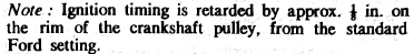
Pictures of my swirl pot to radiator inlet. Hope these are clear. The top of my swirl pot outlet tube is about 1/2" below the bottom of the radiator inlet tube. I will fill the system from the swirl pot then pull the top hose to see how much water is in the radiator.
-
Thanks and yes, I was referring to the top hose.
-
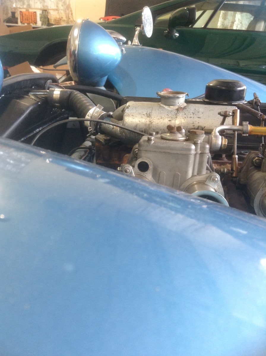
Senc, your swirl pot to radiator angle is much better than mine. I'll shoot another picture so you can see what I'm talking about. Where did you get that lovely flex hose by the way? The one I found (Amazon) is too stiff and my local auto parts don't have anything I can use.
-
I'll be off line most of the day so no testing until later this afternoon.
-
JB, I'm not saying that the inlet and outlet of the swirl pot are reversed, I'm saying that the outlet of the swirl pot should be higher than the inlet of the radiator. Yes, swirl pots remove air but in our application they also are the means to fill the system with water. When the tube to the radiator is below the top of the radiator, an air pocket will remain.
-
Hoses are all new, no rags or other blockages. Everything flows with a garden hose or simply pouring water in from a bucket. filling from the top of the rad flows out the bottom hose, filling from the thermostat housing flows out the pump and lower hose, I can fill the entire system from the rad to over flowing from the thermostat opening. Last test (with the video) was filling the system from the top of the radiator with the front end raised to remove any air from the block. One part of the system that I don't like is the swirl pot exit to radiator is lower than the radiator inlet which means there will always be an air pocket at the top of the radiator.