jmaz
-
Posts
55 -
Joined
-
Last visited
Content Type
Profiles
Forums
Store
Articles
Gallery
Events
Library
Everything posted by jmaz
-
Thanks. The remote, single reservoir that’s serving both the clutch and brake system is a different arrangement compared to older cars I’ve had. Re. the vent hole, should that be in the cover plate over then pedal box? Is the pedal box itself a location for corrosion?
-
As far as I know, there’s nothing unusual about them on this car other than having an up-rated brake master cylinder.

-
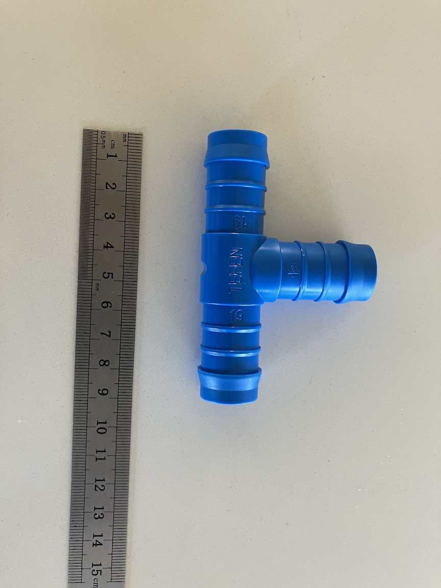
Thanks. I was originally thinking of using one of these types of brass fittings but began wondering if galvanic corrosion between aluminum and copper content in the brass might be a concern, at least over the long term. However, since the temperature sensor "submarine" is brass, as is the fitting for the heater, maybe the addition of one more brass components wouldn't matter. The Gates T-piece has only one barb on each of the arms, so the pex version's additional and probably stronger barbs would be an advantage, as you note.
-
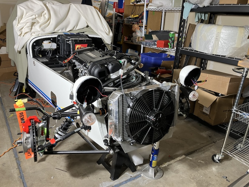
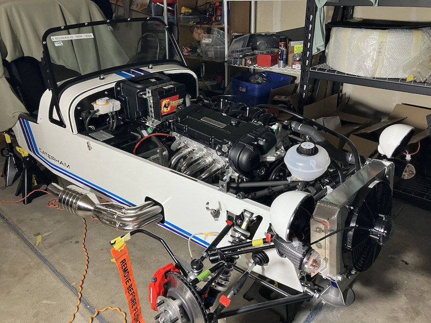
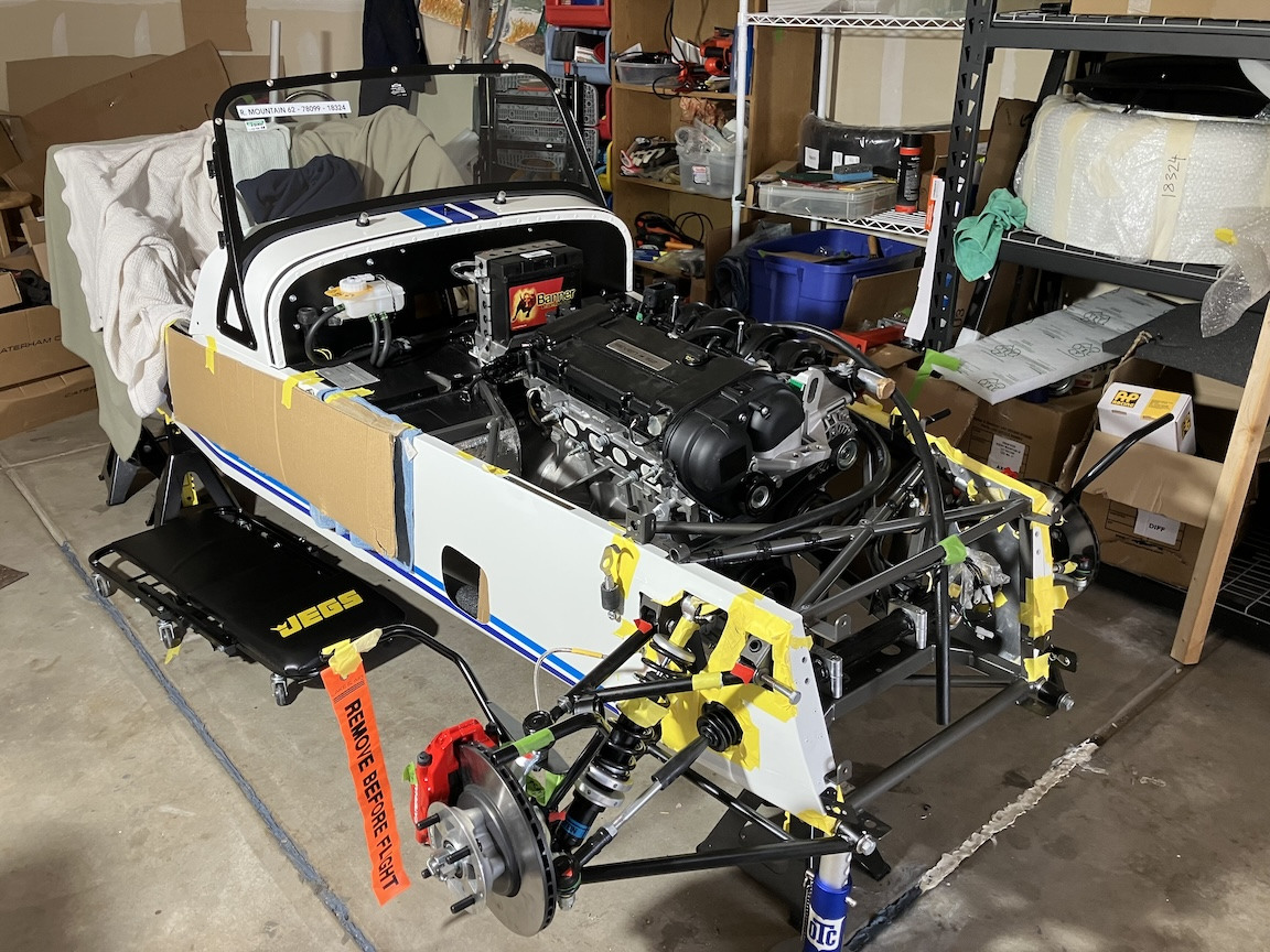
I'm continuing to make slow-but-enjoyable progress on the 310. Some of the more noteworthy things include: Radiator and fan: The 310 Encore uses a 420 radiator with front-mounted fan, with an aluminum deflector plate that gets attached to the base of the radiator. I had to make some modifications to the deflector to make extra clearance for the lower two fan mounting bolts. Engine plumbing: Still not totally done since I decided to upgrade the blue engine-to-modine-to-expansion tank T-piece, and will use a Gates 28635 nylon-reinforced plastic T-piece, following a couple of recommendations received. I appear to be short one hose clamp so bought a replacement from NAPA. The Caterham-supplied clamps have noticeably thicker steel for the clamp band, which maybe yields less stretch over time. Ideally, I'd like to get replace the NAPA clamp with the Caterham version at some point. I'll also go back through the plumbing and wiring to add spacers, zip-ties, adel clamps, etc. where warranted. Headers and collector: This was an easy job, and a treat to add the fun visual aspect to the car. Other issues: The shorter of the two ground cables that Caterham had supplied is too short and won't reach from the battery ground to the mounting point on the top of the passenger footwell. They sent the version used on RHD cars. Rocky Mountain Caterham is sending the correct-length cable. I'm also waiting to get a set of crutch straps (again to be provided by RMC), which I'll install before putting the seats in.
-
Thanks for that kind offer and suggestion re. the pex version. I'd gotten another recommendation for the Gates 28635 T-piece (from Josh Robbins at Rocky Mountain Caterham), so I've ordered one for around $8.00 from Amazon. It seems like one of those strange ways in which Caterham does things, where they could easily and cheaply upgrade a part but choose not to.
-
For my 310 Encore build, I'm considering replacing the supplied, blue-plastic T-piece that connects the engine, modine and expansion tank with the one recommended here (Gates 19mm T-piece, part # 28635) (https://caterham420detailedbuildblog.co.uk/2019/12/19/engine-plumbing-part-1/) or a stainless steel version. The Gates one (nylon-reinforced plastic) is designed specifically for auto use and might be more durable overall. Any suggestions or experience re. this t-piece would be welcome.
-
Thanks, this is useful info, for sure. It's a bummer that a LHD pedal box has limited adjustment. I haven't gotten to the point yet in my build where I'm fine-tuning the pedal situation, but I'd gotten the impression from build blogs, etc. (mostly, if not all, UK blogs maybe, and thus RHD) that there was a fair amount of adjustment possible.
-
Are you satisfied with the CaterLED 3rd brake lights? Any issues with the installation?
-
Your Spitfire's got a carburetor, not fuel injection, right? I'm trying to remember all the things that would go off on my former carbureted cars - TR4 and BMW 2002. Clogged jets and fuel filters weren't unusual. You note that the car had been sitting for a few years. Had the old gas been drained? The other common failure source was burnt or out-of-gap ignition points. Thing about the old technology is it was usually possible to get the cars to run, even if poorly. My newer (former) fun cars (Alfa Spider and Ferrari 328) were more of the "either runs or doesn't" mode. I'm hoping that my Caterham will be more predictable and easier to diagnose/fix.
-
Was it the pins that weren't fully seated in the connector body, or was it a problem with the connectors themselves?
-
What 3D print model did you use for the Spa mirrors? Is it one that you can and are willing to share? What type of print filament did you use? I figured I'd try to get the Eccles version mounts from somewhere, but no idea how long that might take. Ordering anything from the UK these days seems to be a crap shoot, what with tariffs, backlogs, etc.
-
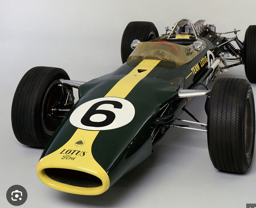
A black stripe + nose band like the old Lotus would look very slick. Wasp-like.
-
I really like how your car looks in solid yellow/gold with no stripes. I didn't notice if you're planning on adding any, but it's a cool look as-is
-
The build continues to progress at a very gradual (comfortable for me) pace. No problems so far. Steps completed to date include front suspension, engine+trans, roll bar, steering, heater, throttle cable, front lights (although not yet connected to the Econoseal connectors), other engine electrical connections, 4-point belts (will install crutch straps when I get them from Josh at RMC as part of my original order), Next on the list is radiator+fan install and engine plumbing. Here are a few things I've noted with some of the recent work: Headlight Wiring: I could have done a much better job of making the wires a more even length prior to heat-shrinking everything. At some point, I'll probably re-do the pins to shorten and even out the wiring into the Econoseal connectors. I'm debating whether to put the stock headlights in place or spend the money now for LED upgrades before final headlight assembly (I'm considering the Morimoto Sealed6 lights, wired for turn signal + DRL function). Steering Centering: Trying to center the steering (in the process of installing the steering column) by counting steering U-joint rotations between full left and right lock didn't seem precise enough, so I used the method shown in https://www.youtube.com/watch?v=HEPW0Zz8qoU which involved sliding the boot(s) off the steering rack, and then measuring the distance between the steering rack stops. It might be enough to measure the distance at full stop in one direction and then just divide by two, but I measured both sides of the steering rack to play it safe. The maximum travel was 10 cm on each side, so I set a distance of 5 cm per side to center the steering. U-joint and Steering Column Alignment: It's recommended that, if necessary, the steering rack be rotated on its long axis to get as straight as an alignment as possible along the steering rack U-joint and the lower steering column. Even with the rack mounting brackets very loose, I was having trouble rotating the rack until I realized that I also needed to loosen the lock nuts at the tie-rod ends so that the rods could rotate along with the rack. Probably should have been obvious, but I'm finding that, for me at least, I'm saying "duh" to myself quite a bit during this build. Upper Steering Column Bush: Most people note that it takes some force to push the rubber bush with its white insert into the dashboard opening for the upper steering column. I struggled with this for awhile until I noticed that there were some small spikes of powder coat in the dashboard's bush housing. After lightly sanding those off using a Dremel with a drum sander bit, and also using the suggestion of inserting a 1/2" ratchet extension through the bush to provide something to push against, the bush went into place with moderate force applied (https://caterham420detailedbuildblog.co.uk/2020/01/29/steering-column/) Battery Cables: the kit came with two black (ground) battery cables of different lengths. I wasn't sure which was meant for which grounding point, but only one of the cables (the longer one) has a fitting with a big enough hole to fit one of the transmission tunnel bolts through if you decide to use that as a grounding location.
-
A good thing to keep in mind is that on most types of pins, the rear "wings" on the pin are intended to grip the wire insulation and serve to anchor the pin, while the front wings should grip just bare wire. This helps when looking at how much insulation you want to strip off, and how you want to position the wire in the pin when the pin's being held by the crimping tool.
-
Yep, your blog's definitely a help. The level of detail (including obscure stuff such as the part numbers for the Econoseal pins) is spot-on, and there aren't many blogs on LHD cars. I also found that the 5 wires wrapped in flexible, tight heat shrink to be pretty easy to get through the bracket. Shouldn't be hard to re-do if desired.
-
I wasn't aware that you've got a new blog going. You're doing a very nice job with it! The option of leaving off the indicator pods entirely hadn't occurred to me. It's definitely something to consider.
-
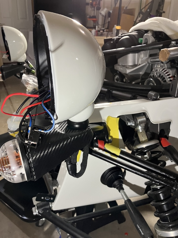
The wire bundle is routed into the headlight mount through the mount's opening+grommet, then down through the mount and into and through the bracket on the forward upper wishbone mounting point (also with a grommet in that opening), and then into the chassis.
-
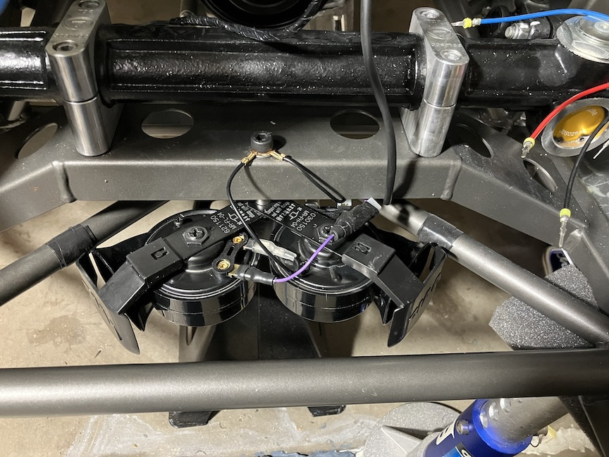
Horns I installed PIAA Sport horns, based on online recommendations. They're noticeably louder than the stock horns. They wouldn't fit in the standard mounting location for the 310, so I used the mounting arrangement for the 420. The Encore uses a 420 radiator with the fan mounted in front, so I figure the horns won't get in the way of anything. I initially thought there might be other good candidate locations on frame rails but nothing looked ideal. The PIAA horns require using separate ground wires (provided). The existing purple power wire set was just slightly too short so I had to add a short extension
-
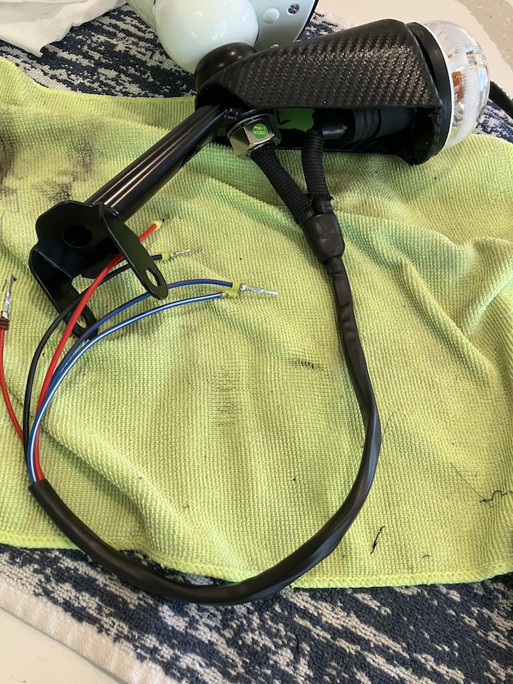
Headlight wiring Finally managed to finish the headlight wiring. I'm not sure I'm happy with the results - the wiring looks pretty bulky. I decided to go with using a "Y" heat shrink piece when routing the indicator/turn-signal wire up into the headlight bowl. I'd also spliced in another wire to the indicator's power wire, and routed that into the headlight bowl as well. My thought is that when I install LED headlights, I hopefully can use that wire to operate the headlight's "switchback" capability to operate the headlight's daytime running light as a turn signal. Unlike the wiring diagrams and in other blogs I've seen, my indicator pods have red power wires rather than green. That now gives me two red wires at the end of the headlight wiring bundle - the sidelight/parking light wire and the indicator wire. The indicator's wire is a darker red, but I'll need to double check which is which when connecting to the econoseal connector. I tried to arrange the wires so that they'd be close to the same length once inside the chassis, but they're off quite a bit. I might decide to trim the lengths and crimp on new pins. One thing I'm wondering about is whether it would be better to send the indicator's ground wire out through the headlight mount and into the chassis along with the other headlight wires and the indicator power wire. That might neaten up the headlight wiring underneath the indicator pod. It would add extra difficulty in pushing the wire bundle through the headlight mount, but that went pretty easily for me. I've found that with heat shrink, the flexibility of the wrap can vary some between different brands. I ordered "flexible" HS from Digikey, along with the Y HS piece. I also used heat shrink fabric from Digikey. I tried some cheaper non shrink fabric from Amazon but I couldn't keep it from getting ragged looking.
-
What you wish you knew before ordering your car?
jmaz replied to Exarkun1178's topic in General Sevens Discussion
In hindsight, I'm thinking that I should have included the master battery cut-off switch. The extra $250 would have been minimal. I can add a battery isolator switch but that's a bit of a kludge, and not trivial if I want to put in a switch that's accessible without removing the bonnet. hood. What do we call it here in Caterham world? -
I found mine (NAPA Evercraft) https://www.napaonline.com/en/p/BK_7761236 on Facebook Marketplace. I bought it for $250, still in its box. I figure I should be able to sell it for $100 or so, later on. Renting is certainly a reasonable option but having one of my own allows me to work at my own (slow) pace. I thought I'd be able to easily rent one from Autozone or O'Reilly's or the like, but when I checked, none of those places actually had any available to rent.
-
Yep. As I noted, 1-ton may have struggled to provide the necessary height. Lowering the chassis a lot might have worked but then it's hard to work under the car. Plus there's the concern of having a lot of weight potentially extending out past the ends of the hoist's legs. My hoist was on the higher-priced side, even as a Facebook Marketplace purchase, but the design, including the action of this hoist's hydraulics was very smooth, which helped with positioning. Another feature that's useful is to have the built-in T-handle on the frame. This helps with making slight adjustments to the lift's position and angle - important for getting the engine+trans in the right place
-
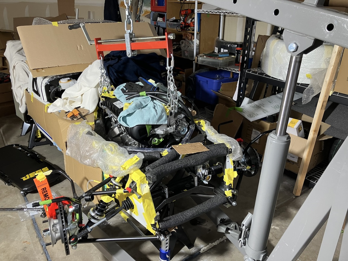
Chassis protection and engine in I went whole hog on trying to protect the chassis, but I found that the transmission bell was so tight in the front of the tunnel that I had to remove all of the protection in that area. Mainly cardboard. In hindsight, it might have been better to just tape some plastic sheeting over the heat shielding in that area. As the blogs recommend, I'd also wrapped the entire transmission and gearbox in plastic. The install was easier than I expected. Blogs and guides suggest keeping all of the bolts loose (the engine-attached mounts, the rubber frame mounts, and transmission bracket), and then gradually shifting the assembly around until things line up. I had a really good helper who grasped the need to take work very slowly and carefully. It took us about 3 hours total, including final torquing of the bolts. The load leveler I've got is longer than most. That extra length gave me more leeway for adjusting the tilt of the assembly. The lift is a 2-ton version. I don't know if a 1-ton lift would have provided enough lifting height in this case. The only extra prep work I'd found necessary was to run a thread tap through the frame bolt holes at the rubber mount locations. In the end, everything was a very tight fit. How do people fit a Duratec into an S3?
-
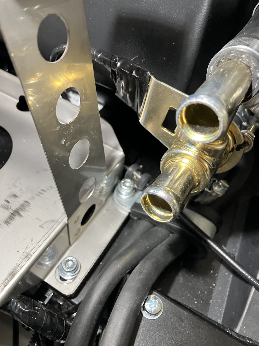
I added an adel clamp attached to the battery tray bolt to help anchor the heater cable. I also wrapped some silicone tape around the portion of the heater valve, where it looked like it might rub against the back of the battery.