chrisp993
-
Posts
26 -
Joined
-
Last visited
Content Type
Profiles
Forums
Store
Articles
Gallery
Events
Library
Everything posted by chrisp993
-
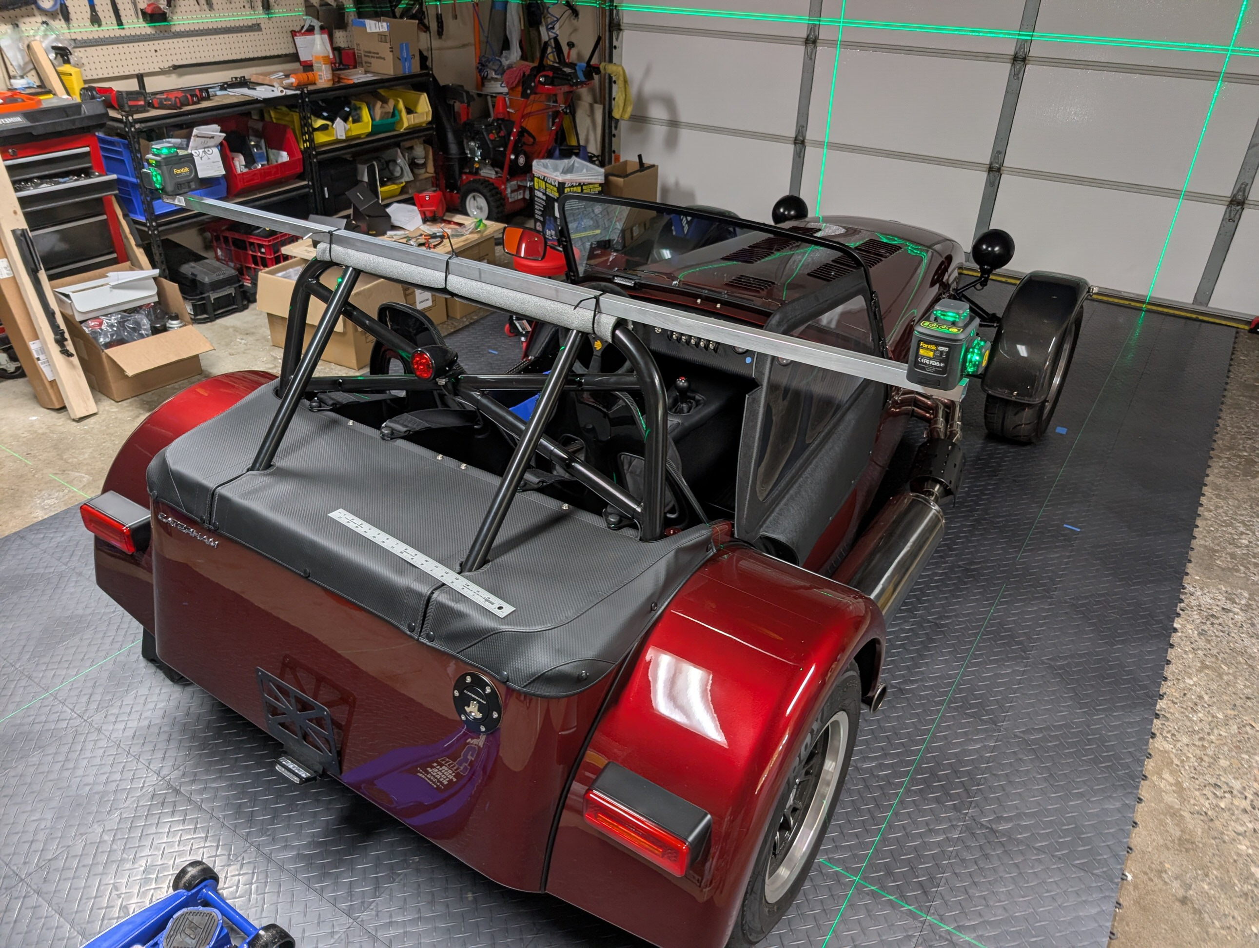
Setting it up square was easier than I thought - once aligned left/right to have the laser "wall" be equal distance from each rear hub, the mount was pivoted around its vertical axis to get equal distance from each front hub. Since the mount on the rollbar is close to the rear axle and I started with the laser lines "eyeball square" to the car, only slight pivoting was needed (since small pivot at rear axle = significant distance at front axle) and it did not disturb the rear hub distance any measurable amount. UPDATE: Testing, setting up the laser box, from scratch, took ~ 20 mins. I did realize that the laser line span where it's mounted to the bar is constant and so you can use an accurate measurement of that to check the box all the way forward and back. So once you have this measurement, getting the box "square" is fast, then just need to carefully nudge the bar left/right and rotate to make it align with the car.
-
Rushing to finish my build I performed a very rough alignment. But I had plans for using 360 degree lasers to replace the "string" in a traditional string alignment. I also came up with a very inexpensive chassis height checker. More details at Chassis Height Checker and Laser Alignment blog posts. Overall this seemed a success! I'd be interested in feedback on the alignment method and whether anyone else has gone down this path?

-
Quick update that my build is complete and I'm now putting those frustrating break-in miles on the car. Blog still needs work to improve referencing and navigation but most of the content from my build is online.
-
Good advice. First drive was 2 days ago (blog needs to catch up) so I have some basis for evaluating. Still think the brake and gas pedal would benefit from being swung down, but also think I need to adapt my pedal usage to the caterham box. Mostly ... I'm enjoying the drive 😁
-
Alan To loosen the forward nut: like you I could not reach it from above, so had to reach into the pedal box and break it loose with a wrench, once this was done I could reach my fingers in from above and spin it freely. Tightened it by the same method. Hope that helps? Chris
-
Can you elaborate on what you did? I'm trying to understand if you bent it side<>side to be closer/further to the brake pedal or if you bent it to be closer/further away from the seat i.e. which axis did you bend?
-
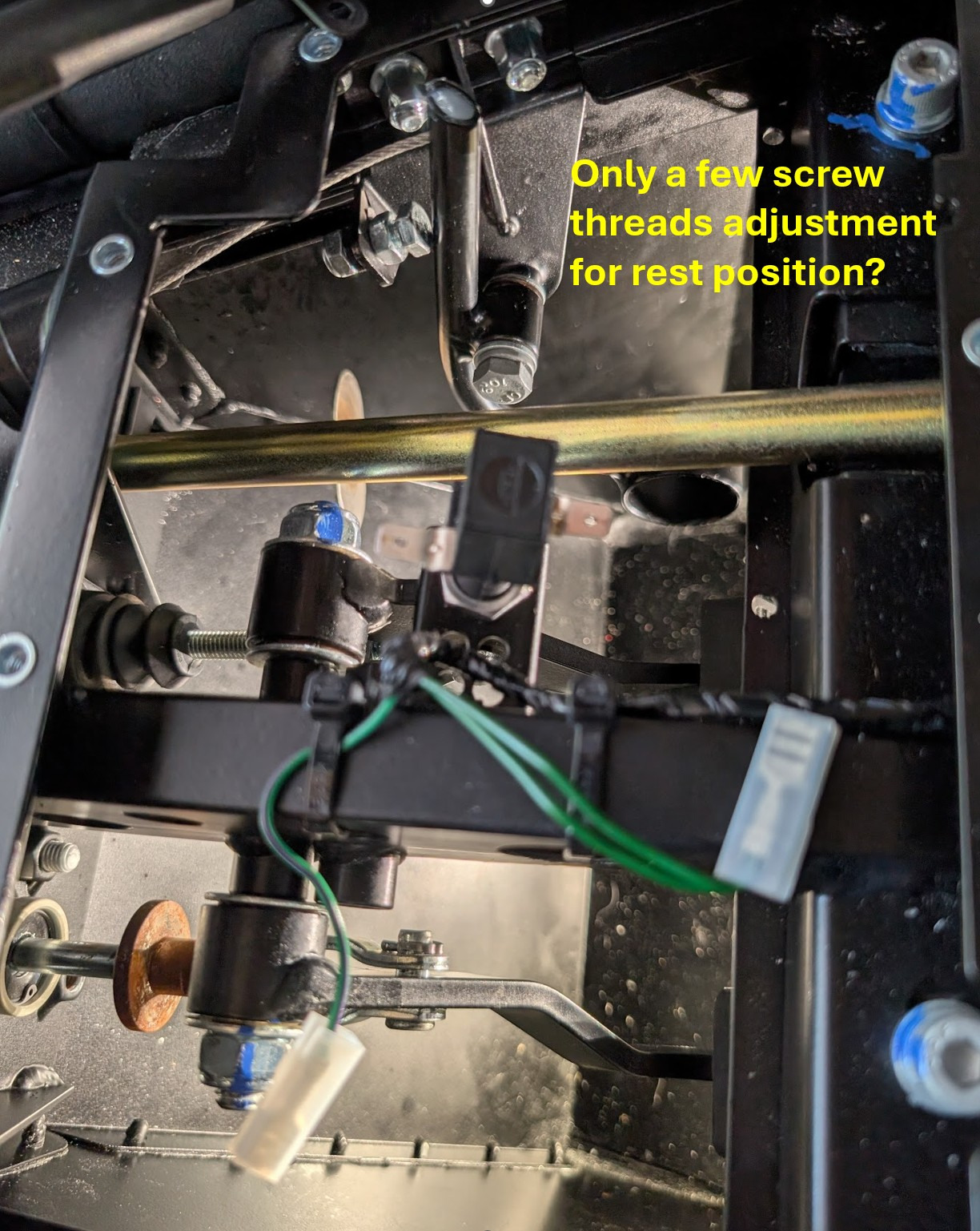
Having thought about Caterham's response and looked again at the gas pedal arrangement on my LHD pedal box: The two nuts at the throttle body take up the slack in the cable, so need to be adjusted to do this without causing the throttle to be > zero. This doesn't alter pedal position in the pedal box. The adjustment where the cable enters the pedal box adjusts the starting position of the pedal - unless limited by the small bolt at the top of the gas pedal. The spring on the throttle body will push the cable "in" to the pedal box, so the threaded entry to the pedal box will change where this rest position sits. It will not adjust the cable slack in any way. The pedal stop on the firewall needs to be set so that there is WOT at the throttle body as the gas pedal hits the stop.
-
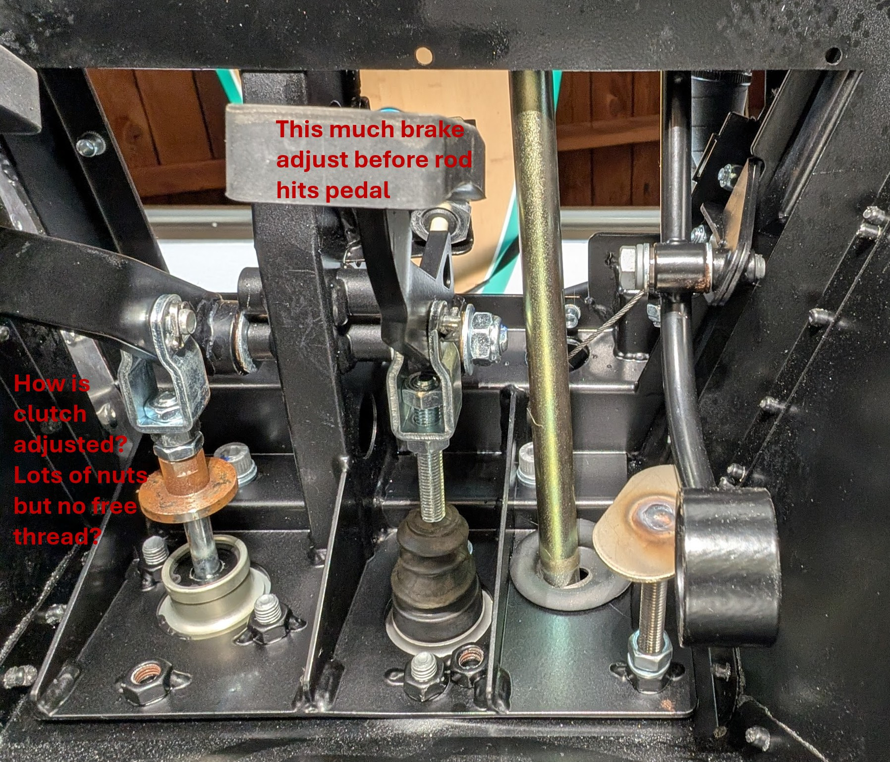
I posed my question to Caterham's build support team who were good enough to provide a very detailed response. TLDR version is that unfortunately the LHD pedal box has very limited adjustment. The full exchange with the build support team (lightly edited) is reproduced below: The LHD pedal box is very different in comparison to a RHD setup. The master cylinders are a different specification and are mounted much lower down on the pedal box, so although you are a bit more limited in terms of the amount of adjustment that you can make to these pedal, it is still possible. Brake: confirmed that adjusting the brake pedal position is limited in terms of how far you can wind the threaded rod into the pedal clevis before it begins to contact the rear of the pedal. To arc the pedal further away from you requires shortening the threaded rod accordingly, but you would need to be careful not to limit the overall pedal travel. Clutch: adjustment is incredibly limited in its standard form. It is possible to switch the half height nut contained within the pedal clevis with the full height lock nut and thereby gain a few mm of adjustment. More than this would require removing material from the face of the clutch stop, allowing you to wind the lock nuts further down the threaded rod and lower the clevis mounting position. Gas: the bolt fitted at the top of the throttle pedal arm is used to set the amount of free play in the pedal when it is a rest and should not be used to set the position of the pedal. Setting the position of the pedal at rest is done through adjustment of the cable, using the adjuster nuts at both the pedal box end and the throttle body end. Once the throttle is in the desired position, you should adjust the pedal stop accordingly so that the pedal meets this at full throttle, and you should adjust the upper arm bolt so that the pedal has approximately 2mm of free play when at rest.
-
7Westfield, thanks! For the clutch, the lower nut is a locknut for the clutch stop so needs to stay. I could remove the middle nut but then would have to lock the clevis against the clutch stop locknut i.e it's a two position option, stock or remove one nut (or possibly source a half height?). Really seems like this adjustable setup should actually ... adjust. Still feel I'm missing something! Brake is probably OK at limit of adjustment. Don't want to cut pushrod until I know what I'm doing ... one way trip! Gas pedal, yes, that was my conclusion, and easy to get a longer bolt! Still just confused ... online searches show easy adjustment of the RHD pedal box 🤔
-
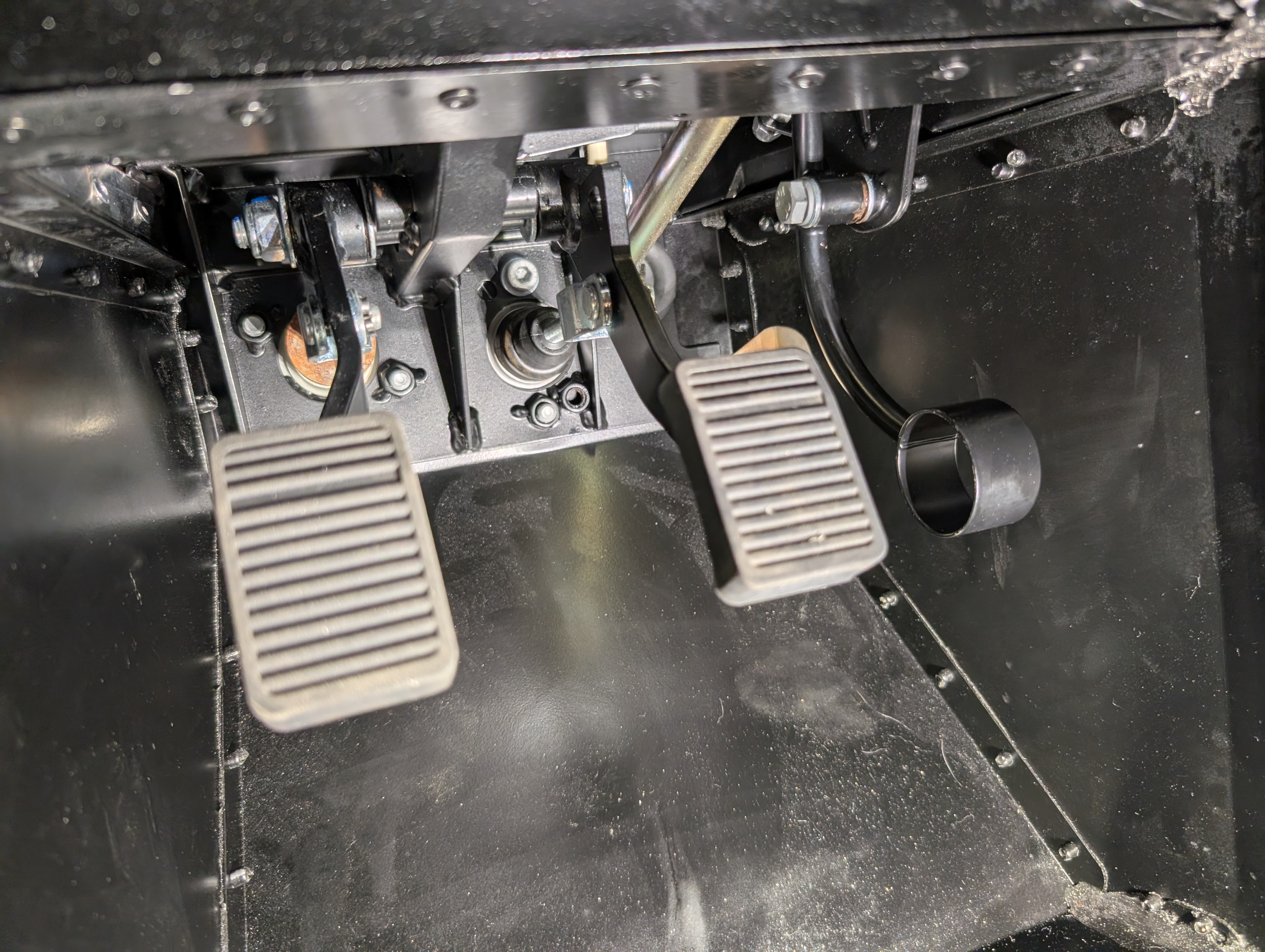
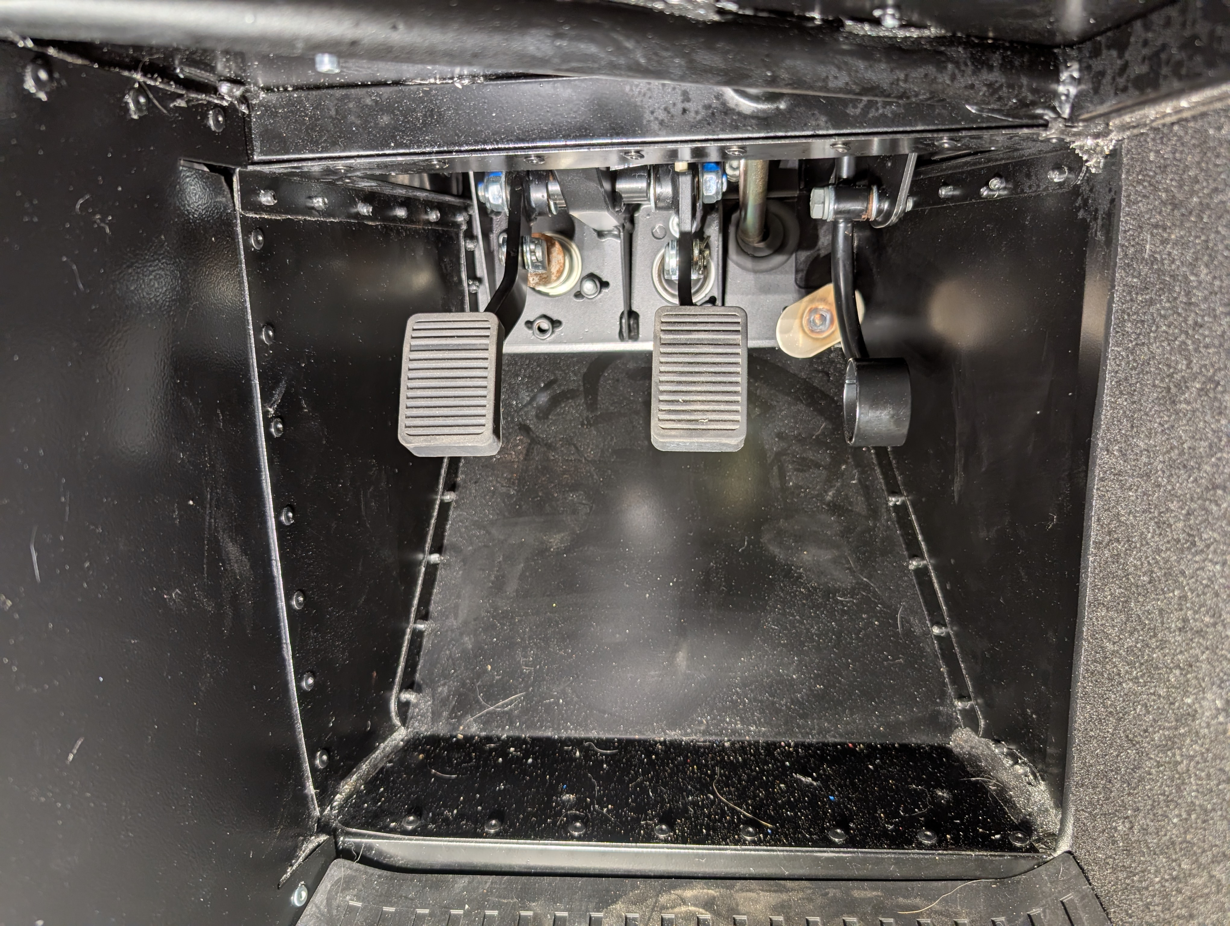
Two more pictures ... the brake pedal is adjusted as low as it will go, feels OK Gas pedal seems too high, much higher than brake pedal when brake is depressed Clutch is a little high, would like it save as brake but per my original post there doesn't seem any adjustment in the clutch withiut altering the clutch stop.
-
Thanks for the reply! Different to the two pictures I attached? Can you be more specific on what you want to see?
-
Just used my Motive bleeder with the European adapter to fill the system on my new build. Previous cars I have followed your friends path of leaving my Motive "dry" and relying on the fluid in the reservoir but this time, since I was filling a dry system, I filled the reservoir and put the balance of 2 quarts of fluid in the Motive tank. Straightforward and much less hassle. The only downside of putting fluid in the Motiv tank is some waste fluid (so, say $5) and cleanup, which was completed (after disconnecting!) by draining the excess and pouring in some alcohol / water mix then using the Motive pump to flush that through the tubes, then letting everything air dry in the sun 👍
-
So, I'm closing in on the end of my build and wanted to adjust the pedals ... the brake and clutch seem set too high, I almost have to push down on them toward the floor vs. pushing them more horizontally toward the firewall. Anway, today I opened up the pedal box and spent a very frustrating time trying to figure out adjustments: Brake: mounted with a pin and clevis to a threaded rod, I ( eventually!) worked out that since the nut was captured within the clevis, turning the threaded rod would move the brake pedal along the rod toward the firewall and in so doing move the "arc" of pedal movement in the direction I wanted. But there was very little adjustment, really less than 1/2" of rod before the end of the rod butted up against the pedal. But this might be enough if I can get the clutch and gas pedal to work with it. Clutch: plenty of locknuts etc. but no actual freedom to really move these without moving the clutch stop - which seems like a bad idea. I'm stumped on how to make any real adjustment to the clutch pedal Gas: assuming Brake and Clutch are lowered, the Gas pedal will also need to be swung down in order to match. The WOT throttle stop is easy to adjust but the resting position has a ridiculously small, couple of threads adjustment - do people switch this out for a longer nut in order to move the resting position lower, or am I just misunderstanding? I feel like I'm missing something with all of the above - attached some pics to try and show what I mean. Can anyone who's ventured down this path help me out?
-
Jmaz ... I just installed the steering column and your post gave me one of those "I'm so dumb" moments. In my case, I reasoned that since the tie rod ends were 12 turns out ... I *assumed* that meant they were both the same distance from rack center and by measuring the wheels straight ahead (ref. rotor edge to front lower wishbone bolt) I could set the wheel straight and then insert the lower column in the rack at that position. Done. But, of course there is that assumption in there ... Long story short (the detail is updated on my blog post) based on your comment I went back, taped a zip tie indicator to the steering hub and looked for how that ended up when at full lock each way. Sure enough it was almost (but not quite) even; full lock right was about 15deg right from vertical whereas full lock left was about 5deg left from vertical ... I was close, but no cigar. So, disassembled (hey, loctite works!) and moved the lower column one spline CW and, bingo, I was there!
-
On the Econoseal pins it's a bit different - and I got it wrong! I was doing a little digging into pins and seals - specifically why I had grey seals vs. stock yellow and whether this made a difference - quick answer on that is that colors do correspond to wire sizes, but they aren't that consistent and the important thing is to choose a seal that is "snug" on the wire. But in going down this rabbit hole, I found that on Econoseal, the rear wings are actually meant to grip the seal and not just the wire insulation. This is shown in BigCol's excellent post on Fitting Econoseal Connectors - scroll down for the picture and you'll see what I mean. I think my connectors are OK, but pinning them in the proper way ensures the seal gets pulled into and really plugs the connector. And now, my OCD exists in this world where my connector seals are not quite 100%
-
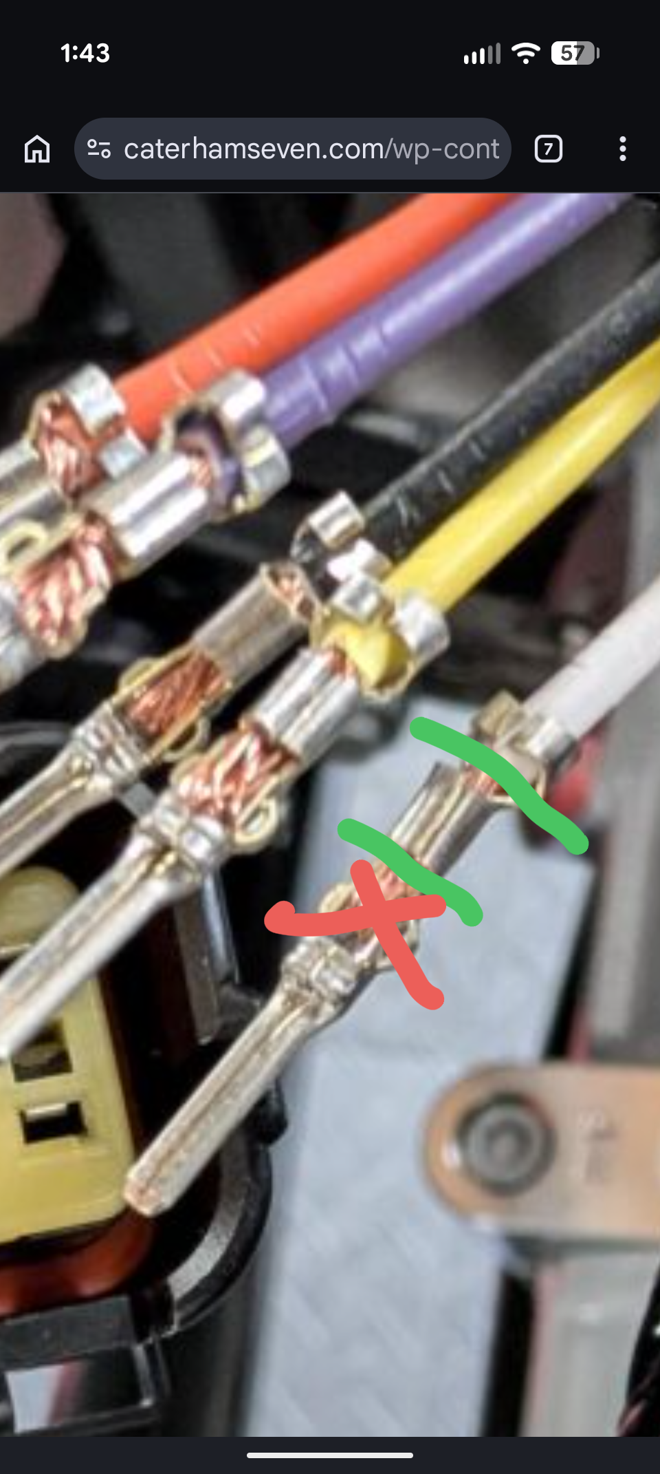
Done properly you only need a tiny section of wire, enough for the forward crimp on the pin, so cutting and re-pinning should only lose ⅓" or so of the wire. In the picture you only need the wire between the green lines ... the section I've crossed out is surplus (my sloppy work, too much bare wire on all the pins!) and in fact occupies the space that the connector's internal catch needs to click into in order to retain the pin.
-
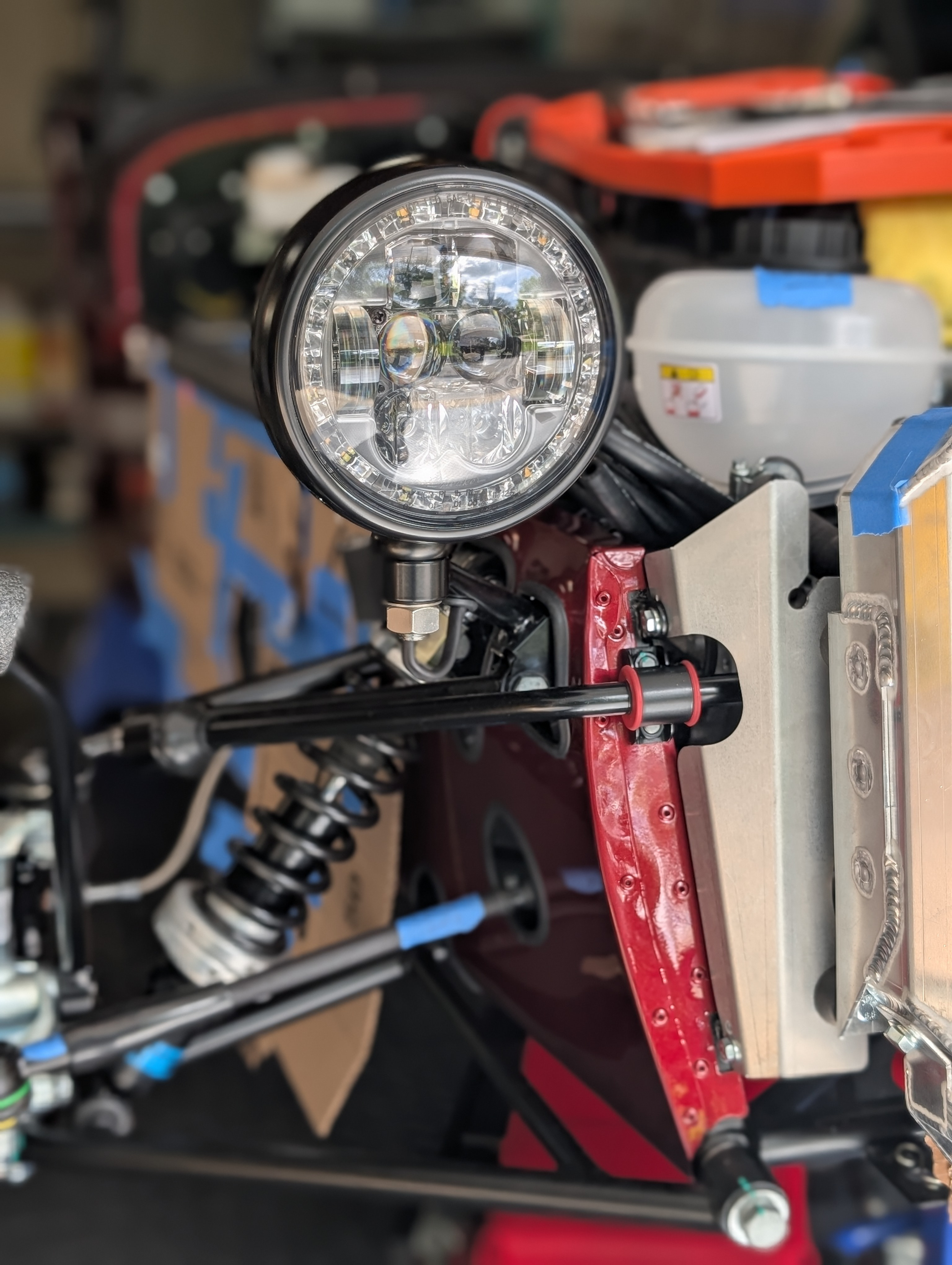
Quick experiment with some black self-fusing silicone tape .... seems like a clean black out solution? And I know from past usage, this stuff is completely weatherproof.
-
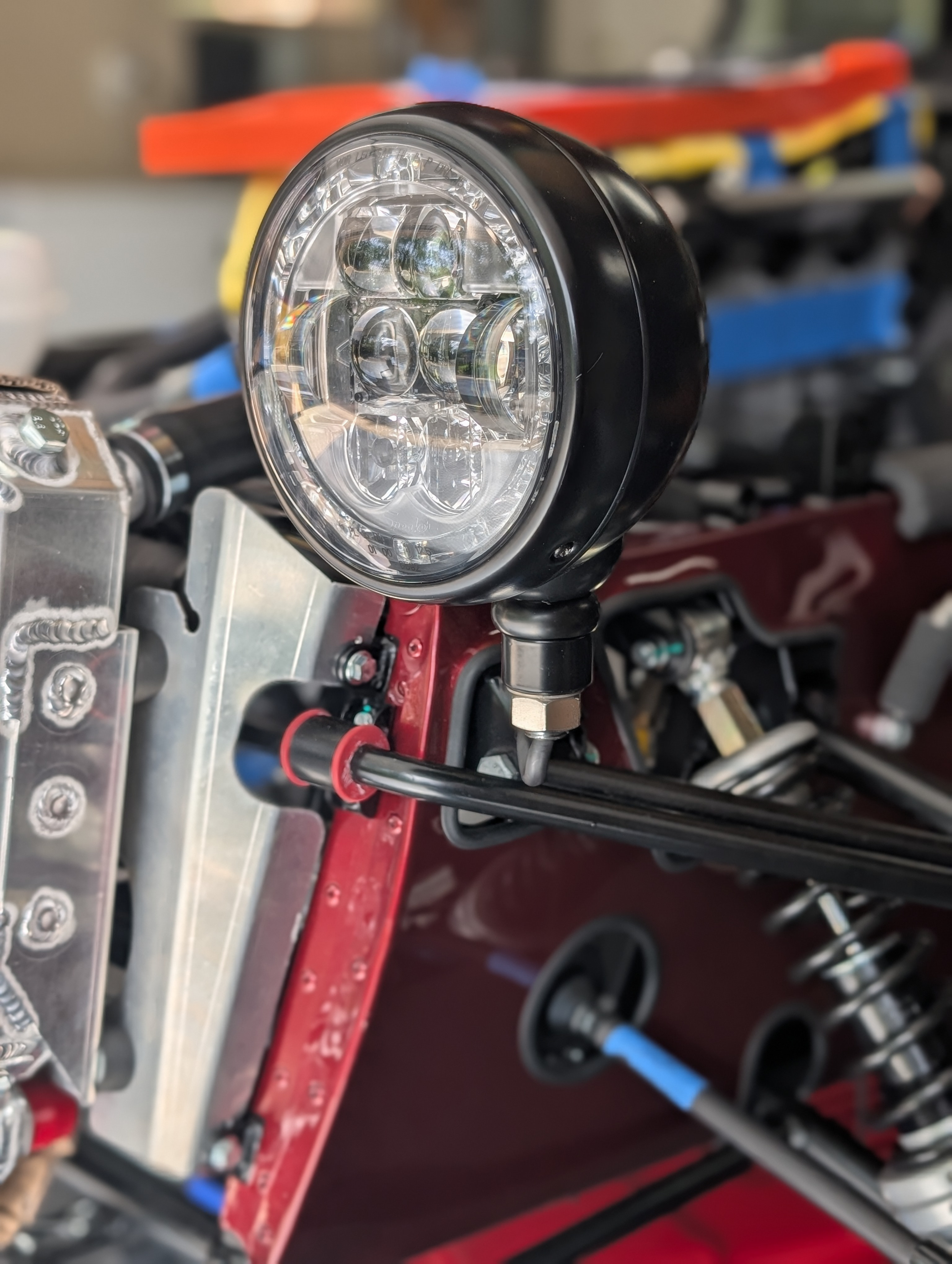
Thanks for the complement - like the car, the blog is a work in progress! Hopefully it's a resource for others as I've really leaned on blogs for help. And a record for me as my memory fades! FWIW, tightly bundled in heat shrink - and crucially, without pins - the 5 wires from the headlight were no problem to push through the bracket. I did slide the grommets off and spray silicone lube but I wouldn't worry about doing it again. For me the PITA and most time spend would be the need to replace the pins. OTOH if you didn't want to replace the pins, then the wires would be trickier to to be fed back and I'm guessing could only go through the bracket one at a time? That would also limit heat shrink to just the headlight end, not the full length? Regarding the look ... I don't think I'll really know if it looks weird until I put the nosecone, hood and front wings on. I'll try and remember to report back when I get to that point.
-
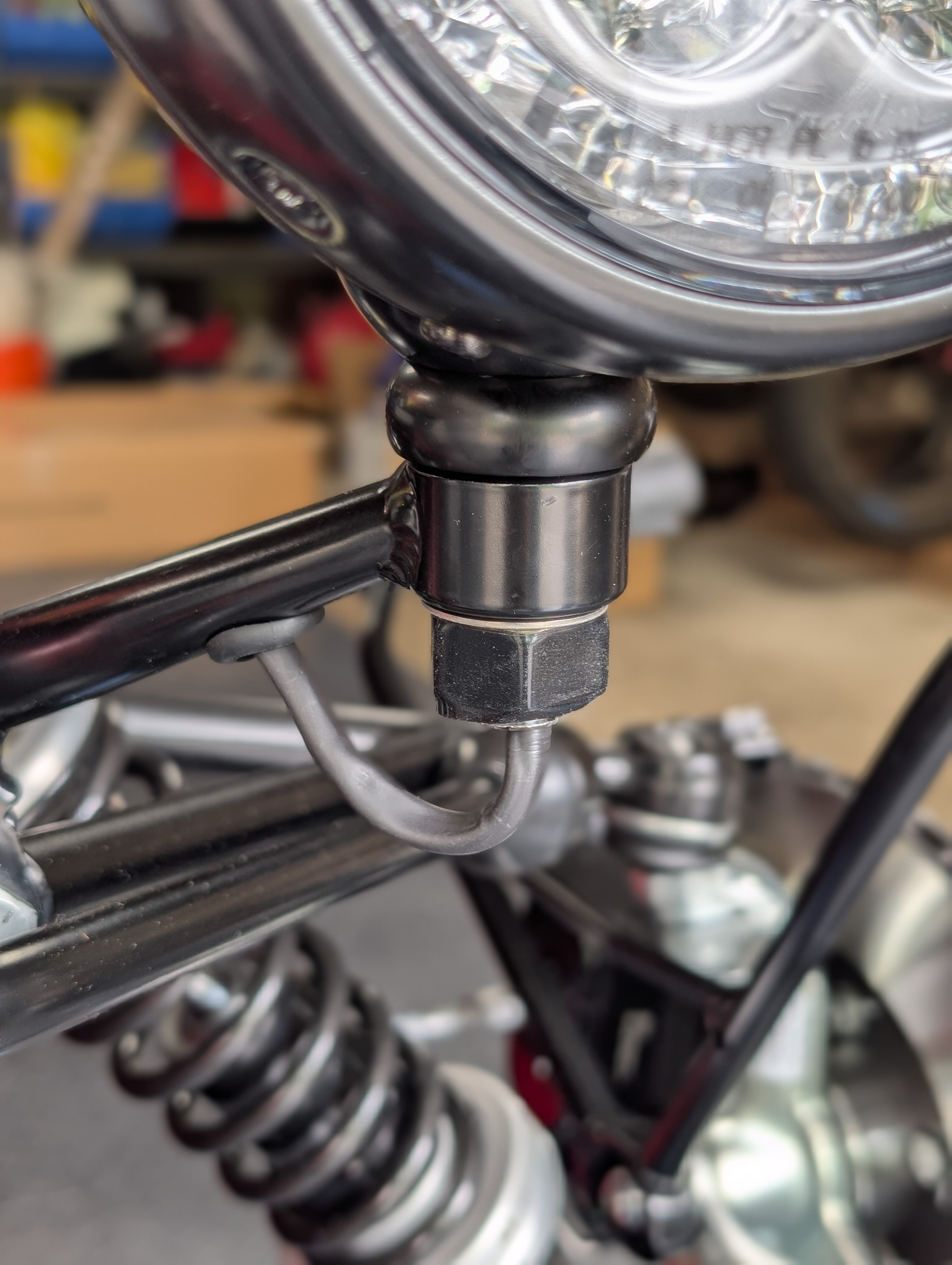
Gotcha. Sounds like you need to repin the end of the wire with a new pin? What parts did you buy? Check my blog post for the exact pin (which did match OEM) that I bought. Message me, I'd be happy to send you a couple of those pins in the mail if you think that would help? Car is still in build, but hopefully these give you some idea? I just need to black out that large nut!
-
Howard, is it the crimp on the pin/connector in the engine bay that is bad? Can you tell if it's the chassis side or the headlight side of that connection? It is straightforward to remove the pin from the connector using a very small thin (like jeweler's) screwdriver, you just need to pull out the yellow guide and then release a small tab: video example. If the pin crimp is bad, you may be able to improve it by putting it in a crimp tool and trying to crush the crimp a bit more. Alternatively, the tool and some pins is maybe $40. When you ask how does it look, which part did you want a picture of?
-
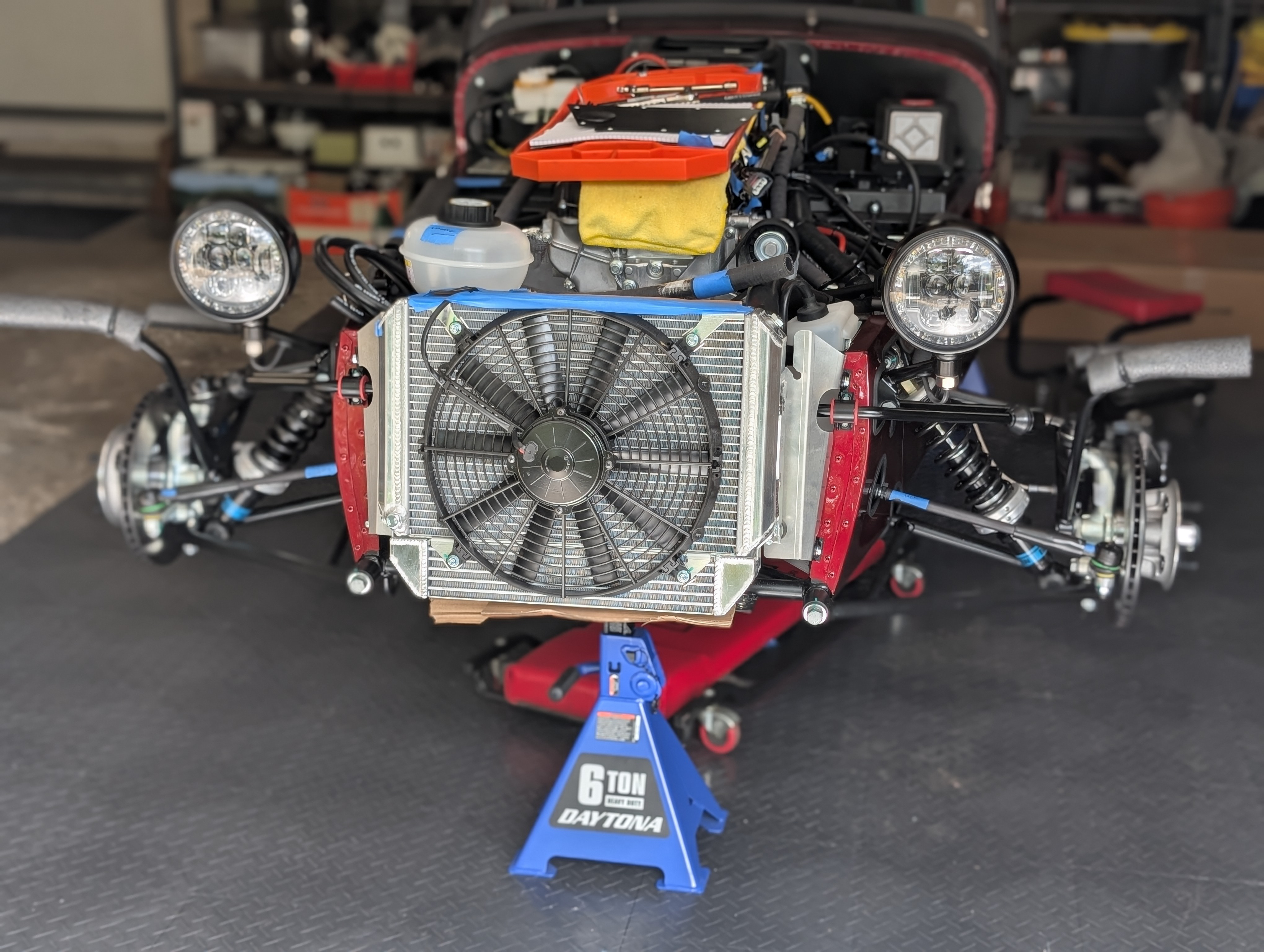
I also just completed the headlight wiring for my build - long blog post here - but the short version is that I ditched the indicator pods and went with aftermarket LEDs (integrated turn signals) and just took all the wiring through to the engine bay where I crimped on pins to match the factory wiring.
-
 Imagining Crockett & Tubbs in this ...
-
Thanks ... and good point!
-
Thanks for the offer! May need some help with details ... the Build Manual can certainly be a bit vague and a quick photo of a Greg-built car could be the perfect answer. I still go back and forth on the color. Have always loved green (with yellow, but like your silver stripe as a more modern choice!) but was tempted away by something a bit brighter. Hopefully won't offend to many with my comment 😳
-
Hello! I've been lurking for a while but am in the early stages (second week!) of building a 420R. I've decided to blog the build, for several reasons (i) I've found online build blogs to be a fantastic resource and help (thank you!) and so I wanted to contribute what I can back to the group, (ii) documenting the process for myself and (iii) as a way of connecting with the Caterham community. Never blogged before and having a rocky start self-teaching Wordpress, so apologies for any mistakes and expect the format and structure to bounce around a bit ... but for now, the blog can be found at Caterham Chronicles. There is information on the blog about why I'm building, spec etc. I started with installing the engine and am now progressing through the front suspension. I'm finding it enjoyable, frustrating, challenging, and rich with lessons. I'm really happy with the process - hopefully stay that way throughout! Again ... Hello! Any questions, fire away