vstryker
-
Posts
84 -
Joined
Content Type
Profiles
Forums
Store
Articles
Gallery
Events
Library
Everything posted by vstryker
-
That's an amazing backdrop. Where did you get your front fenders?
-
Try this, the Cosworth manual I used for my rebuild: http://dubaipetrolheads.com/biggles/download/CSR260%20_Build_Manual.pdf
-
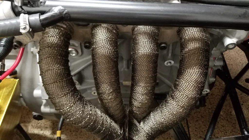
Been playing around on Easimap for over a week and I think I finally like where it's at. Our local MBE tunner guru recently moved so while waiting to find a decent tunner who knows their way around the MBE 9A4, I played with 3 different maps, the SBD base map that I received, the Cosworth 260hp base, and Sean's CSR260 map. Sean's and the Cosworth map were similar but his map was more refined and smoother. I hooked up my friend's wide band O2 sensor, air fuel gauge and made a ton of runs while basically making very small changes to the SBD base map with reference to the other 2 maps. This also helped with breaking in the engine the hard way... progressively loading the engine starting from 4000-7500 in increments of 500rpms. After a few days and about 50 miles, I did the first oil change. Didn't see anything unusual or metal bits so I was happy. By then my modified map was somewhere between the SBD and the Cosworth/Sean's map. This will do for now until I can get a real tuner to look at it. Some minor issues were a bad oil temperature and pressure senders. Also, for some reason, my fan doesn't come on when it's being controlled by thy ecu. It works just fine when it's hooked up the old way where the switch in the radiator turns it on off, so I will have to take a closer look at that. There is alot of heat generated from the headers so i wrapped it, hopefully it keeps th engine bay a little cooler. The 6 speed that I tore apart is much smoother and the power after 4000rpms... sheshh it's ridiculous! 4th gear seriously feels like my old 2nd and it pulls as hard from 3000 rpms to as high as I dare take it in every gear. The new power scares me a bit as the scenery quickly blurs every time I step on the throttle. With that, I think it's fair to say my build is complete. I thought I'd be done by June but like all ambitious projects, with unforseen delays and waiting for parts, I'm glad I took the time to think it through. Finally, a big thank you to some of the board members and vendors for all their help.

-
To adjust voltage you turn the sensor until you see the desired voltage reading. So in this case, you either turn it clockwise or counter clockwise. After adjust it maybe you can screw it on. Check to see if it is pointing in the correct position though as this Caterham is opposite of yours: http://media.caranddriver.com/images/09q4/303952/2008-caterham-7-superlight-r400-duratec-20-liter-inline-4-engine-photo-303960-s-1280x782.jpg If that is the case, turn it around, and readjust. You might have to go into the ECU settings and change the orientation setting: either clockwise or counter. The MBE 9A4 allows full control of the tps sensor including max, min voltages
-
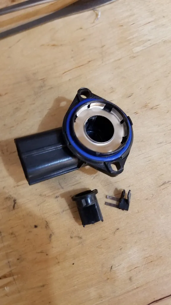
Couldn't sleep all night so I woke up early and was actually able to install Easimap 6 along with the correct drivers for the cable. Hooked it up to the ecu and right away I saw 2 faults... the 1st being the TPS, which was pegged wide open and another for Barometric pressure fault. I don't know exactly what the Barometric fault is but I quickly took out the TPS only to find this: Found the Ford TPS on Amazon which was $20 cheaper than the dealership, who did not have it in stock, and Amazon would ship it by by end of the day. No brainer decision there. By 6pm, the new TPS was at my door. Bolted it up, and using Easimap, calibrated it to 4.60 volts as per procedure. Here's the second time starting it:
-
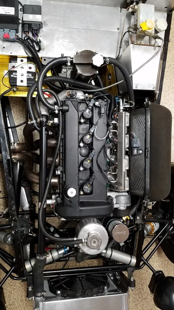
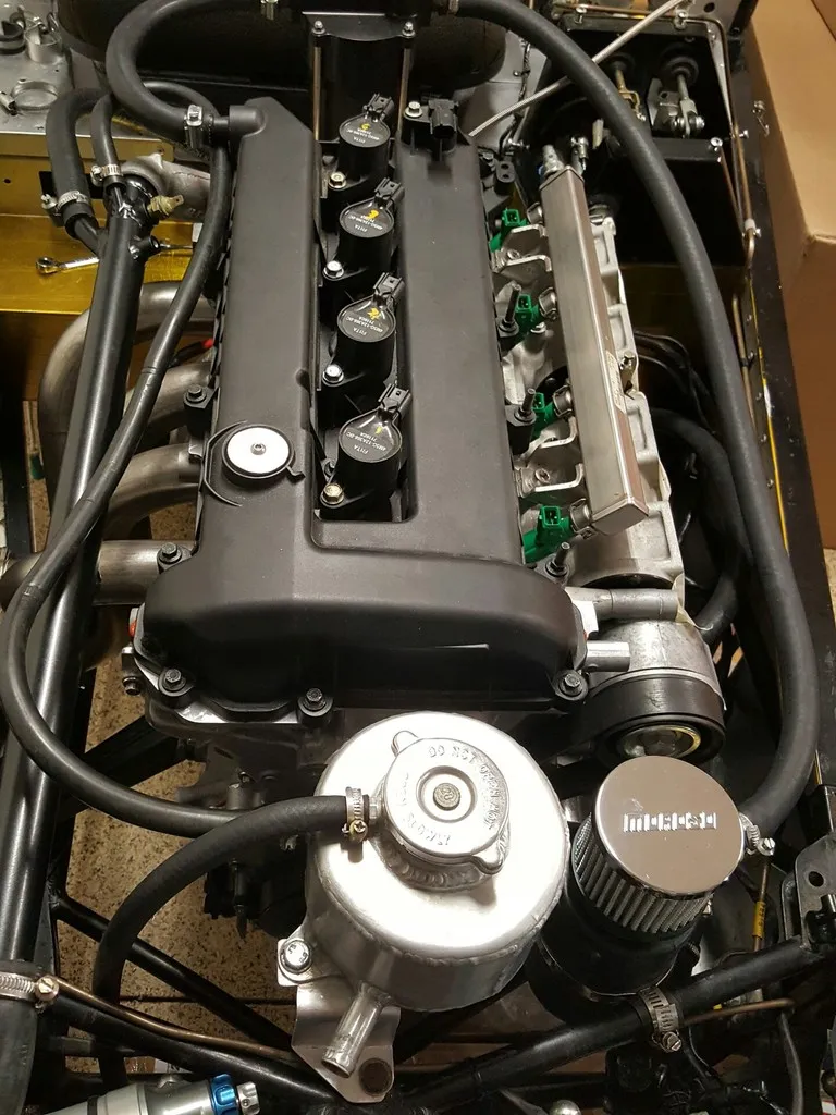
Mounted the battery, ecu and mfru both in front of the passenger. Complete engine bay: Filled the cooling system with distilled water and water wetter. Living in SoCal I opted for the water plus water wetter because it didn't get cold enough here. Took about 6.5-7 liters. Installed oil filter, opened the valve cover and filled the main engine block with 3 liters of oil making sure to lubricate the valve train. Another 3 liters went into the dry sump system via the swirl tower. With the inertial switch disconnected, I cranked the engine using the starter trying to register oil pressure. After about 15 seconds, I saw 2 bars and hooked up the inertial switch. Primed the pump a few times and set the FPR at 55psi. There was a small leak in the return line but was easily fixed by tightening up the fittings. Fingers crossed, I pushed the start button and after 3-4 seconds... the engine bursts into life! I was ecstatic! It had the base map from SBD loaded and since I couldn't get my laptop to install the drivers for Easimap and the cable, I couldn't connect to the ecu. Not wanting to wait, I slowly backed her out of the garage and tried to drive around the block. Of course as soon as I gave it gas, it would stumble and stall with huge fireballs and backfire from the exhaust and intake. It already late so I limped her back inside and called it a night...
-
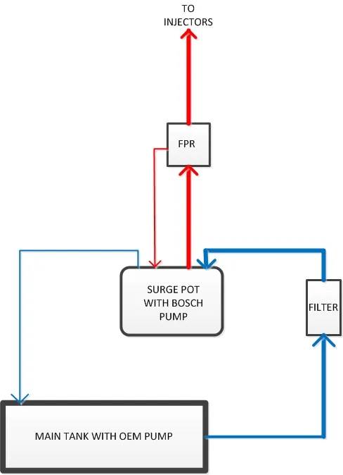
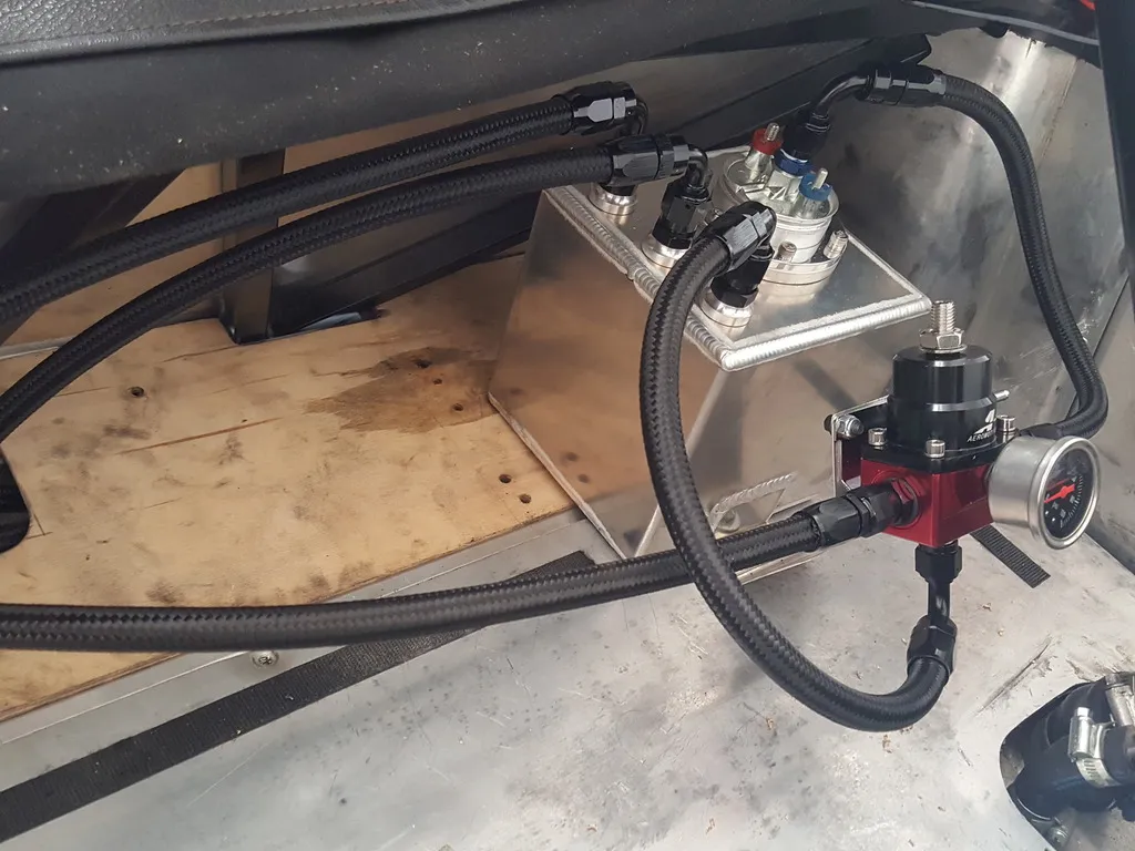
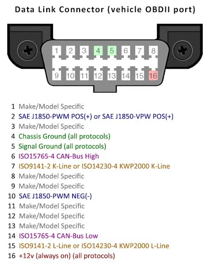
It’s been a while so I thought I’d give this thread an update. After an excruciating wait, I finally received the Caterham Duratec R400 harness along with the crossover harness to mate it to my existing chassis plug since they are different. Luckily, I had the help of Bruce Beachman to build me the crossover. Using the new engine harness, I also opted for the Multi Function Relay Unit (MFRU), and a new electric oil pressure sensor to keep the install clean and easy as possible. A few minor modifications had to be done as described below in order to get everything to fit. Before I could hook up everything, modifications were made to the existing fuel pump wiring since I was installing a secondary Bosch 044 pump inside of the fuel surge pot in the back. Using a wiring guide from Nathan at Thomas Vintage racing, I moved 2 wires around at the Fuel pump fuse block, swap out the 15A fuse for a 20A, and upgrade the wiring to 12 gauge in order to handle the current draws of 2 pumps. To incorporate the existing inertial switch, I tapped the new fuel pump power supply and ground into the output of the inertial switch going to the existing in tank pump. This way, I still had protection and the switch would kill off both pumps. Simple diagram of the fuel surge tank system that I've used on my other cars with great results: 2 liter surge tank, FPR behind passenger boot, might move FPR to engine bay in the future I didn’t realize that I had an older OBD plug until Bruce mentioned that it had to be repined in order for me to have CAN communication and able to flash with the new MBE 9A4 ECU. Repining it was very easy after we got some guidance from SBD. All I had to do was remove the unused pin 13 and move pin 2 to 6 and move pin 10 to 14. Pin 6 and 14 are the CAN High and Low which I traced back to the ECU. Pin out for obd connector: The new engine harness had a different lambda plug than my old one and instead of getting a new O2 sensor, I just opted to rewire my old one into the harness. From the electrical diagrams in the build manual, I was able to interpolate and match it with the existing lambda sensor. The fuel injector plugs were also different. I have green EV1 type injectors that came with the motor while the harness was made for EV6 type. A simple adapter bought on Ebay for a few bucks solved this issue.
-
Does one from a 2005 caterham fit? You have pm
-
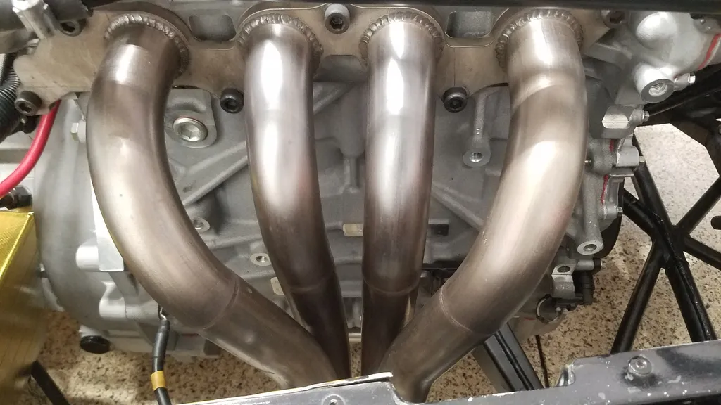
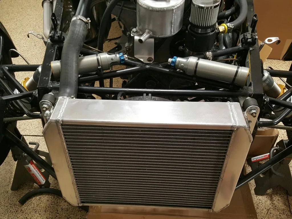
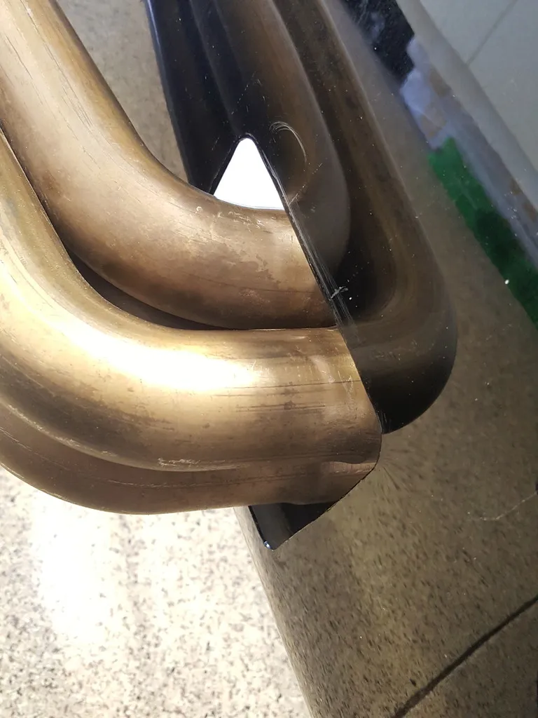
This week I finally got the nice shiny radtec radiator in. Decided to use rubber hoses since it was alot easier to source the ones with the correct bends. This extreme version core is fairly thick at 68mm and should provide plenty of cooling. The black metal return line on the left is from the CSR setup. I made a new mount to raise the expansion bottle higher, hopefully it's high enough as it is at the max height and it barely clears the nose cone. Modification to the oil filler cap was also required to clear the bonnet. I just took the old plastic cap, grounded it flat and epoxied an aluminum cap on it reducing its height y about 18mm. The small allen key allows it to be opened and closed like normal. On the right of the expansion bottle is the oil catch can/breather. There was not enough space on the back on the engine because the plastic can is too tall so that was the only logical place. I don't like how it's mounted with just hose clamps but I'll see how it holds up or if a sturdier mount is needed. I cleaned up the exhaust headers with some 3M scotch brite and had a hell of a time fitting the secondary to the primaries. My fingers and hands are still so sore trying to persuade the tubes to move just 2-3mm, probably wasted a good hour. Right now I have the old caterham exhaust can but I modified my old titanium raceco can to fit as well. This exhaust system is only 2.25" and is probably ok for now but in the near future will have to get a custom headers with at least 2.5 or 2.75" to release this engine's full potential. Now the only thing I'm waiting for is the engine harness. Bruce, if you're reading this, please send me that harness anytime...
-
Hah! A wizard... Far from it, I've screwed up and messed up more times than I can remember. But surprsingly, the Cat 6 speed was relatively straight forward. I wished someone made a dog set of gears for us with different options for 6th like how they do it with all the T9 5 speeds. Anyways, you can get the edge trims at Mcmaster Carr: http://www.mcmaster.com/#edge-trim/=138rmev
-
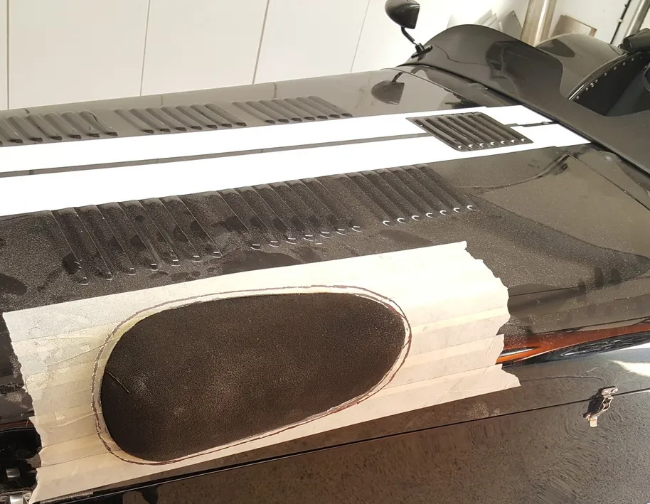
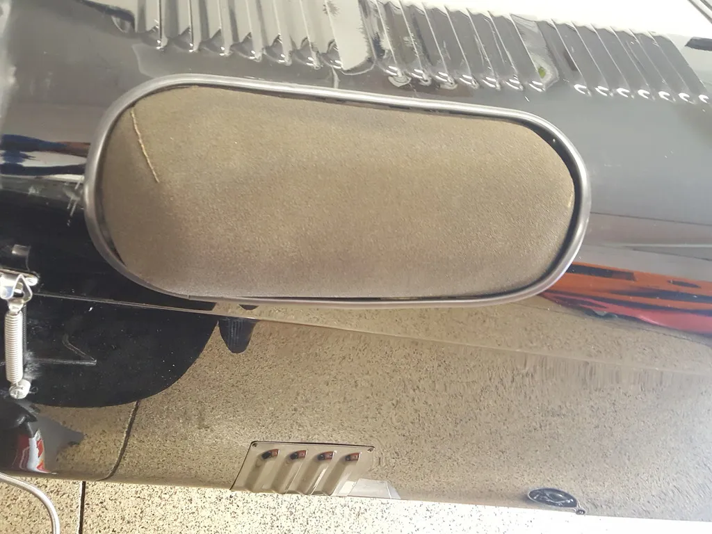
Now it was time to fill in the old exhaust hole on the left, and cut a new one on the right. Used the existing one as a template for the new one. Bought a piece of aluminum louvers on eBay, painted it, shaped it to the bottom contours of the body and riveted it. Here's the new exhaust hole with the manifolds mocked up. I was a bit nervous about cutting the big hole for the intake at first but starting with a small hole and working my way by enlarging it 0.5" at a time, it eventually came out looking pretty good. I was surprised how well it turned out by just using a 3" cutoff wheel with a smaller dremel. Finished off the edges with edge trimmer for a cleaner look. Here you can also see the old exhaust hole covered up.
-
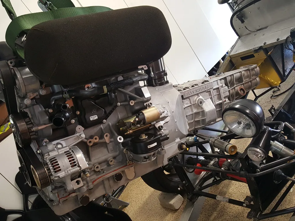
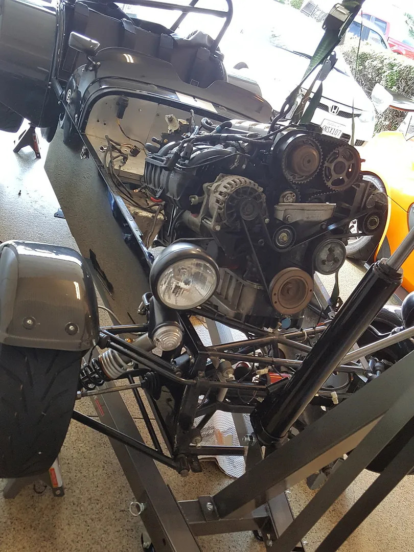
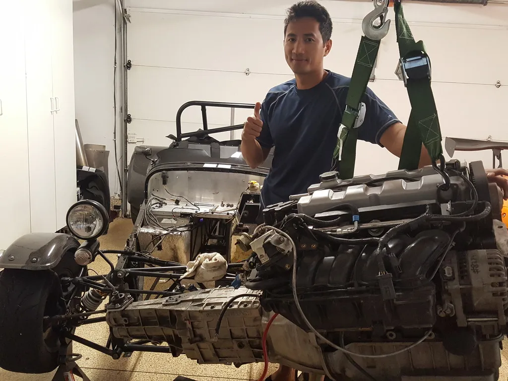
The MONSTER ENGINE is finally in! With the transmission complete and all bolted back together, I bolted it up to the bell housing tank and engine. Using an engine hoist in the front and a jack on the bottom of the transmission as it was going in, it took a bit of adjustments before I could install the 2 engine mounts and rear tranny mount. It was a very tight fit with the 2.3L in a narrow S3 chassis but I'm very happy to report that it all fits.
-
Back on the main shaft, remove circlip slide off 3-4th inner and outter hub, needle roller bearings, and 4th gear. When you slide off the syncro inner and outter hubs, try to remove it as a single unit at first, then later on you can disassemble it but you must keep track of the inner clips on the hub plate as they are different sizes for different sets. http://i25.photobucket.com/albums/c87/vstryker/20160620_131447_zpsmn9bqbjq.jpg Remove front cover and layshaft stub bearing, then the 2 circlips and input bearing at the front. http://i25.photobucket.com/albums/c87/vstryker/Cosworth%20Duratec%20Rebuild/20160625_081308_zpsswynsypz.jpg You can now remove the mainshaft/inputshaft together with the gears and spacer plate as a whole unit. Takes some force, again a bit of pulling, wiggling and it’ll eventually come out. http://i25.photobucket.com/albums/c87/vstryker/20160620_145249_zpsxzgdeu60.jpg To continue disassembling the gears of the main shaft, remove the big circlip and mainshaft bearing on the center plate. Once the center plate is off, the rest of the gears, syncros, and hubs will be easily accessible. To be continued…
-
Remove the other 6 long bolts connecting the tail end to the main case. By tapping the rear end with a rubber mallet, pulling and wiggling you should be able to remove the rear case revealing the rest of the gears. To remove the gear selectors and shaft, punch out the drift pin that is on the arm and pin as seen here. Once this drift pin is out, pull the selector shaft back towards the rear and remove the 5-6th selector along with the 1-2nd selector. You can’t remove the 3-4th selector yet until you slide off 3-4th gear later on. http://i25.photobucket.com/albums/c87/vstryker/Cosworth%20Duratec%20Rebuild/20160625_155547_zpstcpqjwgv_edit_1467828277427_zpstogm62mw.jpg Looking at the main shaft, at the rearmost is the speedo worm gear. Mark the exact location of the worm gear before pulling it out with your gear puller as it has to be pressed back in the same spot. On the main shaft, remove the circlips, external rings, and sliding out the rear bearing. http://i25.photobucket.com/albums/c87/vstryker/Cosworth%20Duratec%20Rebuild/20160620_131417_zpsrv1g2rir.jpg Continue by removing 3rd gear, and syncro rings. Now you can finally remove the 3-4th gear selector by sliding it to the rear and out. In order to remove the rest of the gears on the main shaft, you now have to start working on the layshaft bearing and layshaft 3-4 gears on the bottom. Once you have removed the 26mm bolt on the layshaft, use your bearing puller to pull out the rear layshaft bearing, along with 3rd and 4th layshaft gears and it’s spacer in between. The 26mm was pretty tight at around 90-110ftlbs so it will take vise or a second set of hands to secure the tranny and a long extension to break it loose. http://i25.photobucket.com/albums/c87/vstryker/20160620_094947_zpspduzjhnz.jpg On the layshaft, remove the circlip, then bearing in the center of the spacer plate by sliding the bearing to the rear. http://i25.photobucket.com/albums/c87/vstryker/Cosworth%20Duratec%20Rebuild/20160625_075329_zpszyasygmp.jpg
-
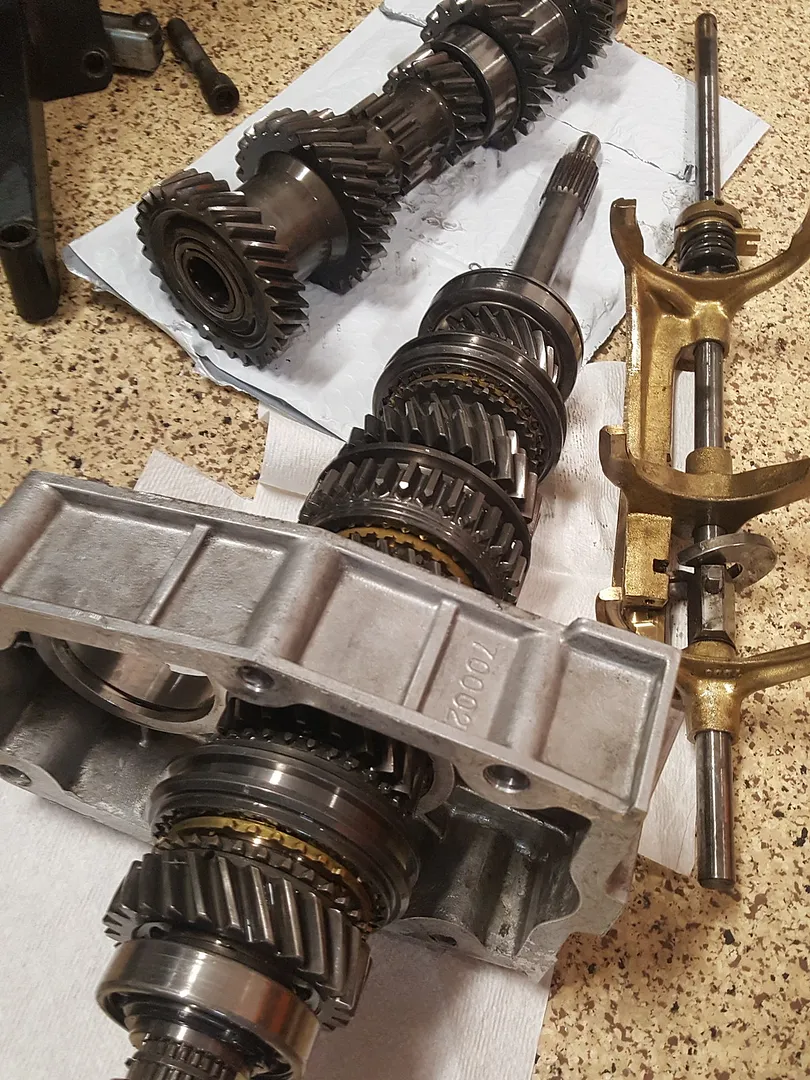
I wasn't planning on rebuilding my tranny, but I had some time waiting for the last few pieces of my swap to come along. Since I had ordered the bearing and gasket kit already when I broke my speedo gear, I said what the hell... I've done only 2 other transmissions in the past and I'd recommend a very good set of internal, external and horseshoe shapped pliers to remove all the various sizes of snap rings, retaining rings and circlips. A good strong set is crucial as the type 9 is filled with them. I used a generic 3 arm bearing/gear puller to help me get the bearing and gears off. Also, keep everything clean, neat and organized with many trays and labels for all the different parts. Take lots of pictures to help you remember where it goes in case you forget later. You can order pretty much all the parts you need from here: http://www.bearingkits.co.uk I used these PDF’s as a reference guide http://mjdtopsites.com/images/type_9-N_gearbox.pdf http://www.sjmmarsh.com/7files/Gearbox_T9_6.pdf Now let's gets started: Here’s a quick overview of the different parts inside and out: http://i25.photobucket.com/albums/c87/vstryker/Cosworth%20Duratec%20Rebuild/Cat6SpeedCase_zps2zrjggif.png http://i25.photobucket.com/albums/c87/vstryker/Cat6SpeedInternal_zps9wi6ta8l.png Remove tranny from engine, bell housing and drain fluid. If you haven't already done so or if you have one, carefully remove the speedo sensor and back up switch sitting on the lower right side. The speed sensor on mine unscrews at the brass portion and then very slowly pull out the quill that is connected to the speedo gear. Then using a flat head, you can pry out the cover on the opposite end. Once the cover is off, you can push the speedo gear through and out on the left side. Remove the small rectangular breather plate on the top rear of the tranny. At the top left corner on the left side of the main case, unscrew the allen plug, spring and plunger. Put it in first gear and then remove shifter. Make sure you also remove the black plastic saddle that the shifter fork sits on. Putting it in first gear allows you to access the drift pin that keeps the selector rail connected to the main selector shaft. I use a small punch pin with the correct size to tap it out. Lightly tap the rear cover plate out from the inside and remove the selector rail and drift pin. Remove the 6 bolts on the top lid of the main case. Looking inside from front to back, you’ll see the brass 5-6th gear selector, and the 1-2nd gear selector. The 3-4th gear selector is on the back end. http://i25.photobucket.com/albums/c87/vstryker/Cosworth%20Duratec%20Rebuild/20160617_041600_zpsyyvsoqrx.jpg http://i25.photobucket.com/albums/c87/vstryker/Cosworth%20Duratec%20Rebuild/20160625_155543_zpsacn6giml.jpg
-
Looks like you guys had a blast! I wish we had something similar on the west coast. Tom, so how was the new tune from SBD? Any more issues with your coolant?
-
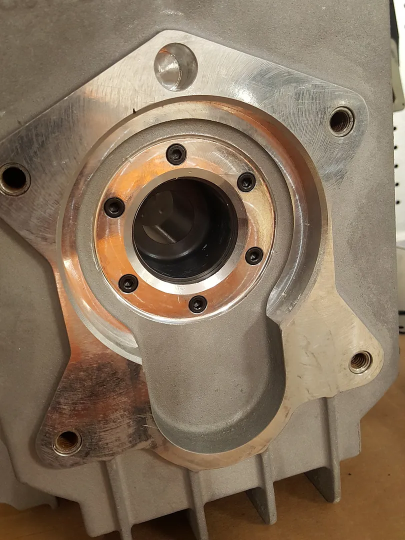
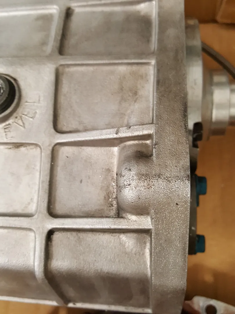
Unfortunately, it looks like i might have an older 6 speed main case as the 4 mounting points are not straight thru "ears" like the newer ones I've seen but they are instead a "boss" type: The good news is that I have modified the "boss" by cutting/drilling them into "ears"and now an allen head bolt will fit from transmisson ears to the the CSR bell housing. While at it, I I decided to tear down the tranny to clean, inspect and replace all the seals, bearings and maybe some syncros if need be. I will probably do a separate write up as it is a whole other job in itself.
-
I just weighed the Caterham 6 speed with no fluids and no shifter, 65 pounds. The whole case is all aluminum.
-
I weighed both engines with the alternator, starter, and oil pan mounted. It did not include exhaust headers, flywheel, or any fluids, so basically the short block. And the verdict is.... Zetec 2.0 SVT : 255 pounds Duratec 2.3 CSR260: 220 pounds Zetec aluminum flywheel, clutch, pressure plate: 26 pounds (Stock flywheel alone is about 24 pounds) Duratec lightweight flywheel, clutch, pressure plate: 19 pounds So all in, I will be saving a little over 40 pounds which was as expected.
-
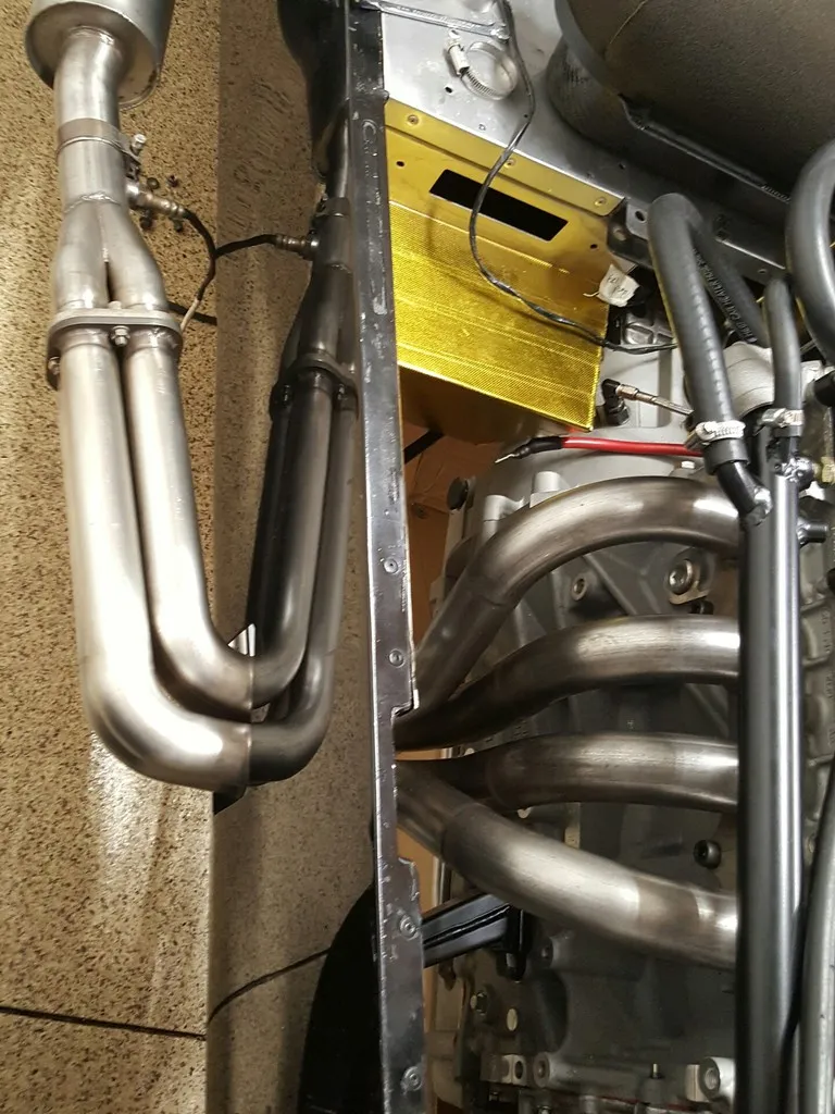
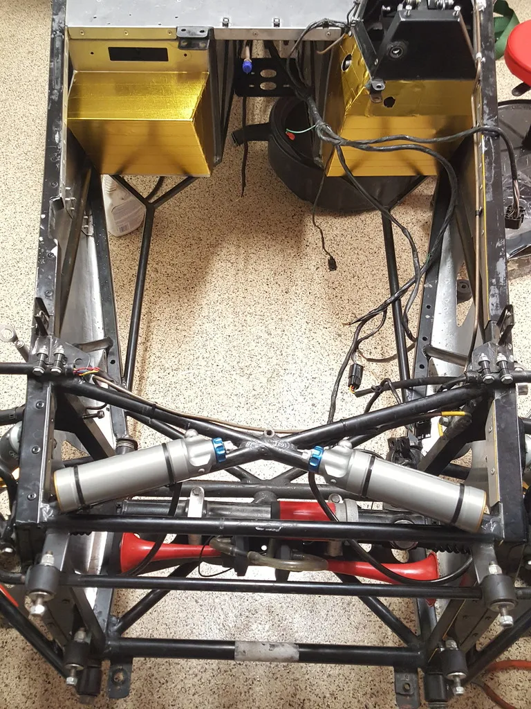
Insulating it with heat reflective gold foil to bling up the engine bay a little. I also had to lengthen some wires in order to move it to the drivers side. I didn't want the hot exhaust headers to melt the wires on the passenger side. Here's after cleaning up the routing of the horn as well as placement of the external reservoirs. Ran into a problem though as I was looking at mating the new bell housing & tranny together. The new bell housing have female threads and so does the tranny. Looks like I have to cut and modify the tranny mounting holes so that I can either use allen head bolts from the tranny side or use studs & nuts. Either way, I'd have to cut & grind the ends of the tranny casting mounts off. The 2 bottom mounting holes look easy to do but the top 2 look too tight. Any ideas on how or what to use to cut/grind?
-
I already have a used duratec header & exhaust system, I might reuse my old titanum ammo can if the setup is too loud. Obvisouly i need to cut a hole on the passenger side and cover up the old driver side hole, I was thinking with some sort of vent like the top of the hood?
-
I've been away for work in the last 3 months and I'm glad to be working on the car again. Radtec Extreme radiator ordered along with the MBE 9A4 ecu. SBD says they will include a base map which is usually good to get it started. But since we bascially have the same motor, our generous forum member Sean sent me his map which I will try until I can get it on the dyno. Thanks Sean! Also received a few things from Bruce, and my surge tank setup is here as well. Prepping to pull the old motor out, I had the car on jack stands while I disconnected the exhaust, primaries, electical conectors including battery cables and grounds, coolant hoses. Next, drained the oil, transmission fluid and coolant. Continued by removing the old radiator & fan, disconnected clutch hose. I broke the speedo sensor & speedo gear while trying to carefully remove it. Took out steering column, fuel line, throttle cable, more hoses & connectors. With the engine being supported by the hoist, I removed engine and transmission mounts. Playing around with the angle, pushing & pulling here & there I was able to get the engine & tranny out in one piece. I will weigh the 2 engines & hope it's a 40-50 pound savings as others have mentioned.
-
Congrats on the baby & welcome home! Let's finish this project already! I've been away for the last 3 months & finally have some time to work on mine again
-
upon further inspection, it looks like I broke the wires & the speedo drive itself, the rest of it is still inside the box. I know I can order a new speedo drive but won't know how many teeth until I take it apart. As for the wiring connection, can it be fixed as it snapped off at the plastic portion? I'm assuming the plugs are the same size between the 5 & 6 speed but not sure on the drive gear... Also, is there an option where I keep my stock speedo working if I convert it to one of the above options? http://i25.photobucket.com/albums/c87/vstryker/Cosworth%20Duratec%20Rebuild/20160530_180948_zpsms163n6n.jpg
-
Well looks like I managed to break my old speed sensor when I carefully pulled it out as I was in the process of removing the engine & 6 speed. Is there an alternative way to get the speedo to work by using some sort of inductor sensor on the front wheels or rear axel? I have a 2005 zetec based S3 Caterham. I'm looking to do this instead of simply replacing the sensor since I've read somewhere you can plug the angle speed sensor port on the caterham 6 speed. I'm annoyed with the 1-2 drops of oil seeping from the old speed sensor so I want to permanently plug it. Also, anyone know where I can get the plugs for the Caterham 6speed/T9 tranny. TIA