EdWills
-
Posts
237 -
Joined
Content Type
Profiles
Forums
Store
Articles
Gallery
Events
Library
Everything posted by EdWills
-
Previous posters have requested information regarding Mick Beveridge of Xtra Special Sevens. I have personally purchased a number of items for my Seven from Mick, and in our last correspondence some time ago, Mick told me that he had not been very well. He is a great guy, a Seven specialist, and an excellent fabricator. Knowing that Tony Ingram of Fast7s has imported some of Mick's parts, I contacted Tony. He advised that 'I know that Mick had lost his workshops and that stopped him from doing any business'. Tony added that there was no contact from Mick anymore... I tried the only telephone number I have for Mick, and got an answering machine from another company now using Mick's number. As I, and others have found, there is no reply from the email address that Mick was using. A month ago I emailed him - just to find out if he was o.k. - but no reply. I sincerely hope that he is o.k., and it is a sad day for him and us if he had to fold up the company. Cheers W.
- 1 reply
-
- 2
-

-

-
Hi Scott. Thank you for the picture. The poor(er)? relative of the Series 2 and 3 seems to have been left out of the plastic model kit world except for the model I have. I was pleasantly surprised when I found it. I was on holiday visiting relatives over the pond and took time to visit Brands Hatch racing circuit with my wife. I got to see one of the (four?) versions of 'Black Brick' in a club race. Owned by Rob Cox Allison, a very friendly/very likeable race car driver, who was perfectly happy to tell me all about his car as he worked on it in the outfield paddock area . Also racing was a standard Series 3 Seven owned and raced by Maynard Soares who won his class (rag top fitted, and when racing, looked like an inflated balloon). I would have liked to see the Lotus 7X racing. I was living in the U.K. at the time that Tim Goss was so successful with the car, but unfortunately had other commitments. I had attended Brands Hatch on Boxing Day a year before, and nearly froze to death. How they raced in such frigid conditions I will never know. Also very icy under some of the bridges. Cheers. Will
-
Apologies. This was sent off before I could load photos. EW

-
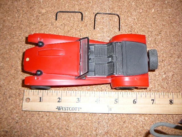
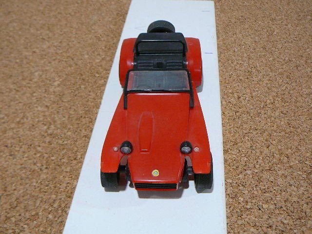
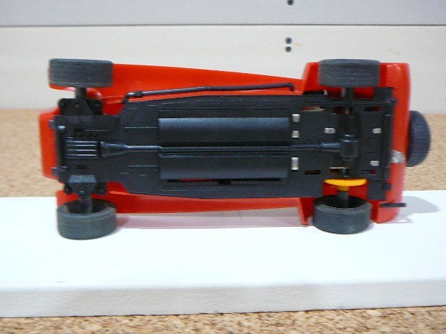
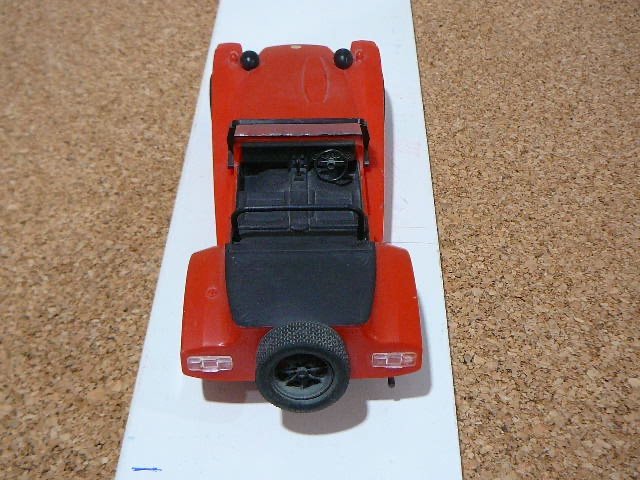
For Sale: 1/20 scale plastic model kit by Nichimo, Japan, of a Lotus Super Seven Series 4. It is mostly assembled, but the roll bar has not been attached in case of breakage. There is no damage on the model. A spare formed black metal wire roll bar is also included. There are not many separate parts to this model, so it came mostly assembled. To split the body from the chassis requires gentle prying at the bottom of the nose cone to release 2 small plastic clips. It can then be repainted if necessary to a colour of your choice. The headlamps, exhaust and windscreen can be removed if necessary for painting or masked off. The model is motorized, and requires 2 'AA' batteries, (but not included as the weight of these drives up the postage cost into the next price bracket!). The model was purchased in 1983 from a stall at Brands Hatch U.K., and sat on a shelf since then. The front wheels of the model have steering capability. I have found a couple of unmade boxed kits on line on e---, but they are very expensive as the kit has not been produced for a long time.. Offers in the region of $75.00 plus postage (tracked and insured).
-
Hi Terry. A number of years ago I required new brake piston seals for my 1969 Lotus Seven which is equipped with the later 14LF callipers from the Mk3 and 4 Spitfire (This information is according to Goodridge U.K.) Girling U.K. has a web site contact option, and may be best to contact as they can go back into their library and advise which seal kit is best for your situation. Goodridge U.K. were also very helpful, and supplied me with a photocopy of all the parts for my callipers. They mostly sell brake hose kits for many U.K. and European cars and did include the Seven, but I couldn't find the Seven kit on their site anymore. Burton U.K. were also very helpful with brake line kits and I obtained a 'vintage looking' set for my Seven from them. You probably know this already, but it is best that you do not attempt to split the calliper bodies undoing the bolts. A new small rubber seal would be required (this can be obtained still as a spare part), but leaks may ensue if the halves are not bolted back together with the correct torque. Lotus and Girling recommended that you should never separate the halves. Good luck with your search and kit experience. EW
-
I should clarify my statement regarding Haynes's valve size specifications for the Ford Escort Mexico in their manual. They are correct depending on the date of manufacture of the cars they were featuring. According to David Vizard in his handbook "Tuning Escorts and Capris", for Crossflow engines fitted up to August 1970, the valve sizes for the standard 1100 and 1300 were 1.41" diameter for the inlet, and 1.25" for the exhaust. The 1300 GT engine had inlets of 1.5", and 1.25" for the exhaust. The 1600 and 1600 GT engine had the same size valves as the 1300 GT. After August 1970, Ford started using the uprated engine, and the valve sizes increased to 1.55" for the inlet and 1.34" for the exhaust on the 1600 and 1600 GT. This was when the flat head was used replacing the head with the slight recess and the bowl in piston with no valve cut-outs. The uprated head required the pistons to have valve reliefs machined in the tops of the pistons. David Vizard advised that the best head for modification was the 1100 c.c. flat head casting. It had much more metal for enlarging the ports, as well as allowing for larger valves. Way back, I purchased at auction a 711M oil pump engine originally from an oil company for $25.00, and the head was fitted with the flat head 1100 c.c. casting with small valves. On a trip over the pond, I took it to Oselli Engineering in Oxford, and they installed hardened valve seats on the exhaust for unleaded fuel, bronze valve guides, and valves of 1.6" inlet, and 1.34" exhaust. They called this stage 2+. Note: 1.6 m.m. is considered the minimum space between valve edges to prevent cracking of the metal between the valves under hard driving including racing conditions. In my case, I have a space of 1.725 m.m. between the inlet and exhaust valves on my cylinder head. (There is a formula for this if interested?) Cheers, Bill
-
Hey Scott. According to the sales blurb for the 1970 introduced Ford Escort Mexico, the engine was a more economical power plant than the one used for the London to Mexico Rally.. The Haynes Manual for the Ford Escort RS1600 and the Mexico 1600, notes that the valve sizes for the Road Escort Mexico are the same size as the 1600 Crossflow pre-uprated engine used in the 1600 Cortina GT and Lotus Seven Series 3.. Seeing as the uprated 711M engine with slightly larger valves was introduced by Ford at this time (used in the Lotus Seven Series 4 and later Formula Fords), fitted with the flat head and stronger block with meatier mains caps, it is possible that Haynes were publishing older specifications for the pre-uprated engine in their Mexico specs. "A good example of a powerful but flexible use of a push-rod engine is given by the units used in the Works Escorts on the 1970 World Cup Rally. These engines were taken out to 1830 c.c. by boring and fitting a specially made long throw crankshaft. The flat cylinder head, with very little work done to it, retained standard valves but compression ratio was upped slightly to 9.5:1 by fitting Mahle pistons. Twin 45 DCOE Webers with 36 m.m. chokes were used and the camshaft was the Holbay R120 (my note: as used in the Lotus Holbay 7S Seven and available for the Series 4 as an extra). Power from this set up was approximately 140 bhp at little over the normal rpm figure. These engines were built with reliability in mind as much as power - and they proved successful, as everyone knows." Quote from "Tuning Four Cylinder Fords by Paul Davies" - published by Cars and Car Conversions Speed Sport Motobooks. So, I'm guessing that someone - perhaps other than Ford - has machined your head to take the maximum size of valves available. You may have to check that the area between the valves has sufficient metal as one tuning website notes that cracks can occur when the head is machined with the valve heads too close together. If I can find this site, I will pass it on to you if you are interested. Cheers, Bill
-
Hi Scott. In the article it shows the rear axle of James Whiting's car. No noticeable reinforcing plate to strengthen and prevent twisting to the axle and no special suspension set-up - just the regular rear 'A' frame. With the maximum 160 bhp on tap from the 1650 c.c. twin cam, and using the car for sprints and drag races, I guess the Ford axle can and did take the punishment without falling apart? James Whiting has another lightweight Series 2 Seven that he rebuilt with lots of alloy parts including gearbox, bell housing, and diff. carrier on it. Being an ex Rolls Royce mechanic, he has enough experience with cars to know what will and will not work. He has an extensive Seven restoration and repair business. I purchased a few sets of spark plugs with different heat ranges from him, and he was very helpful with advice. The magazine also featured Burton Performance in the U.K., who are excellent for Ford parts. Still going strong after many years in business with the same family in charge. Again, very knowledgable and v. helpful. Cheers Bill.
-
Hey Scott. Many thanks for posting this. I found the mag. at my Local Indigo/Chapters Store in Canada, and if anyone needs a copy they have a few left. $14.99 Canadian plus postage. Lots of interesting articles along with the Caterham 7 comparisons plus a description of 2 Lotus Mark 6 cars. Plenty of other great articles too. Cheers. Bill
-
Caterham A Frames - check them as part of your annual maintenance
EdWills replied to Croc's topic in General Tech
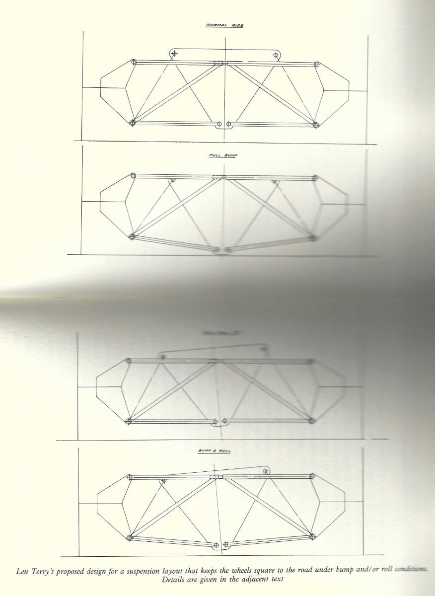
Hi MV8. Correct, the thin lines are the coil overs. Len Terry was quite a character, and I had a few emails back and forth with him before he died. Regarding the layout shown in his book, he advised the following: "It comprises two simple frames, each forming a triangle with its 'upright', connected to a sliding joint. Each frame is located by a parallel-arm lower link, as shown, and by the usual top and bottom longitudinal radius arms which are not seen in this view. In the drawings the body is depicted purely diagrammatically to indicate the attachment points. This system keeps the wheels perpendicular to the road under any combination of bump, rebound and roll, and the lateral sliding travel at the central joint is less than half an inch. Unsprung weight is clearly rather higher than for a conventional rear suspension, but the advantage of no camber change could well outweigh this, and the structure does fit surprisingly well into the layout of a normal open-wheel racing car". Apparently, Len Terry did not incorporate this design into any of his cars, or those for Lotus (too bad!). Just an aside. Way back when Lotus was going up-market, they would sell off many of their sports and racing car spare parts at the factory. They would bundle them into wooden tea chests, 2 feet x 2 feet x 2 feet or so, and you purchased the tea chests more or less items unseen, not knowing what was in the middle and bottom of the container (you were not encouraged to dump the contents out at the factory apparently!). A friend of mine purchased one of the chests from the factory, and inside were a pair of new cast alloy rear uprights, drive shafts, brake parts, wishbones and lots of other assorted bits and pieces from their Formula Ford cars and other G.P. cars. The price, according to him, was quite reasonable, and he planned on using some of them on a couple of Lotus formula cars that he owned, as well as a Seven. Best, Bill. -
Hi Scott. The Series 1 and Series IV Seven had the battery mounted in the boot. It would probably require a smaller capacity fuel tank to accommodate the battery as per the Series 1 unless you can mount a fuel tank above it as in the Series IV. In the photo above, it appears that the boot board is sitting much lower than normal for a Seven, so allowing the battery and fire extinguisher to be fitted there. With the de-Dion set-up on this particular car, there should not be a problem of the differential case hitting the underside of the lowered boot board (a definite possibility with a solid rear axle car) as in the de-Dion set-up, the diff case is bolted firmly in place. You can check SimpleSevens.org, and search the 'History' section, click on 'David Porter's 7/20' article, and at the very bottom of this section there are photographs of the bare chassis of a 7/20 look-alike race car. In one of the photos it shows the bracket for installing a battery at the rear on the opposite side from the driver. The fuel tank in the 7/20 is smaller than the regular Seven Series 2 or 3 tank. Caterham had a battery bracket manufactured by Arch for their Sevens that fitted on the passenger side of the car in front of the firewall in the lower engine bay area. Tony Weale noted that it may be difficult to service the battery in this location, and Caterham resorted to using a 'no maintenance battery'. If you check the Odyssey Battery web site, there are various sizes of dry cell batteries that may be suitable for your use. USA7s has a forum page detailing various batteries for the Seven with recommendations from owners. Cheers, Bill
-
Caterham A Frames - check them as part of your annual maintenance
EdWills replied to Croc's topic in General Tech
Hello Gents. Although this design is perhaps not very practical for a Lotus Seven due to the cost and complexity of the system, this drawing of a De-Dion rear suspension by Len Terry would have complimented his other arrangement for the rear suspension of the Lotus Type Three Seven race car. The Terry design in the attached drawing is still in the Lotus vein with the small diameter tubular frames for the De-Dion suspension (as opposed to the large 3 inch? diameter tube used on cars such as the Lotus 11 and the Seven Series IV Clubman car). Note: Regarding the drawing, unfortunately, my copier doesn't work that well, and although I tried to eliminate light, it didn't work - my apologies. The 3rd picture should read 'FULL ROLL' and it looks like 5 degrees? I really like the look of this layout, and it would be an interesting project if time and money allowed. Cheers, Bill
-
Caterham A Frames - check them as part of your annual maintenance
EdWills replied to Croc's topic in General Tech
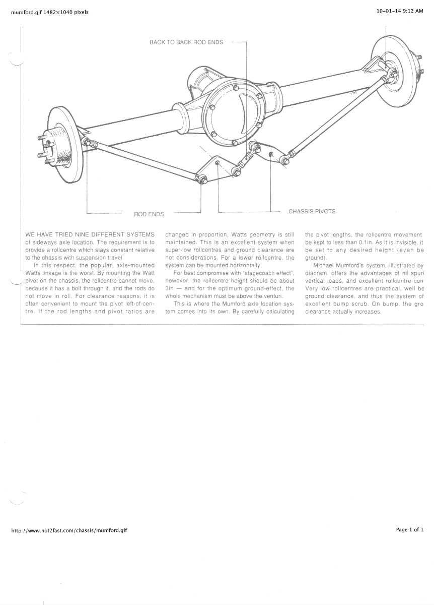
Hi MV8 and Scott. Attached is Arthur Mallock's take on locating a solid rear axle in a sports car using a Watts linkage system and disc brakes. The very early Mallocks were fairly similar in appearance to a Lotus Seven. Arthur Mallock advised me that he worked on a number of Sevens in the U.K. for customers who raced their cars. As noted previously, this modification may not/would not be sanctioned by various U.K. motor racing bodies. Unfortunately, the extreme right hand side of the notes are cut off when being copied. This is due to U.K. paper size being different to that in North America. Mr. Mallock used long, almost parallel radius arms either side of the chassis to locate the axle fore and aft, but the attachment points are not shown in this diagram. Cheers B. .
-
Caterham A Frames - check them as part of your annual maintenance
EdWills replied to Croc's topic in General Tech
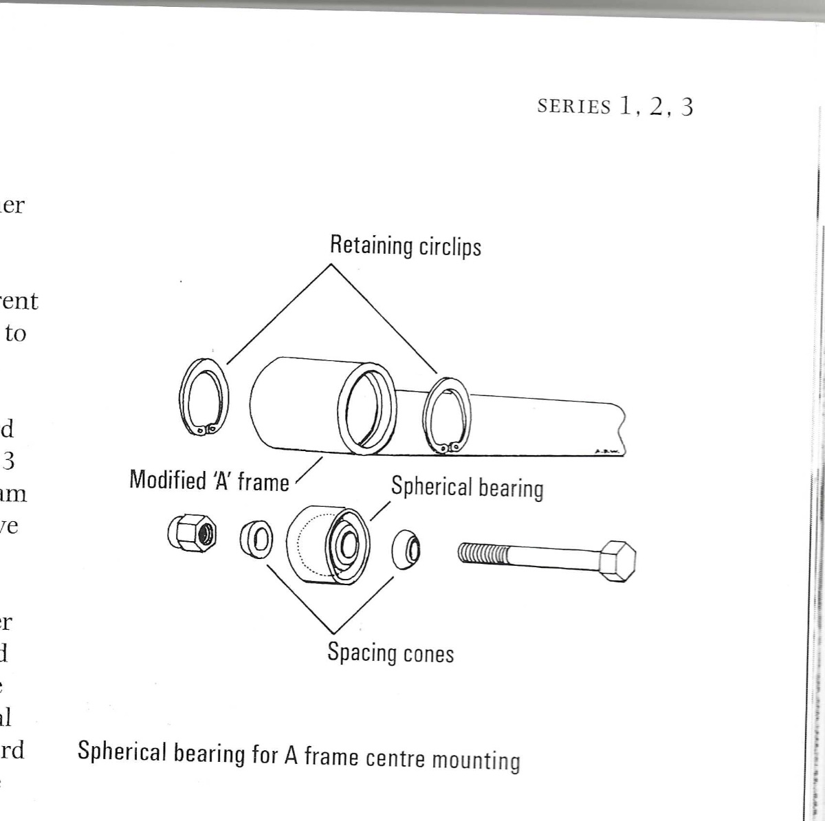
One more image to add from Tony Weale's book on the Lotus Seven as requested. by MV8.. It shows the mounting of the spherical bearing mentioned in the post above. Happy New Year to all.
-
Caterham A Frames - check them as part of your annual maintenance
EdWills replied to Croc's topic in General Tech
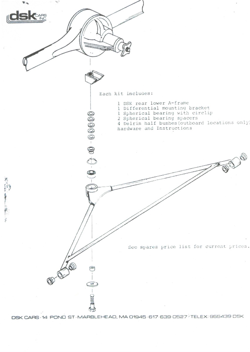
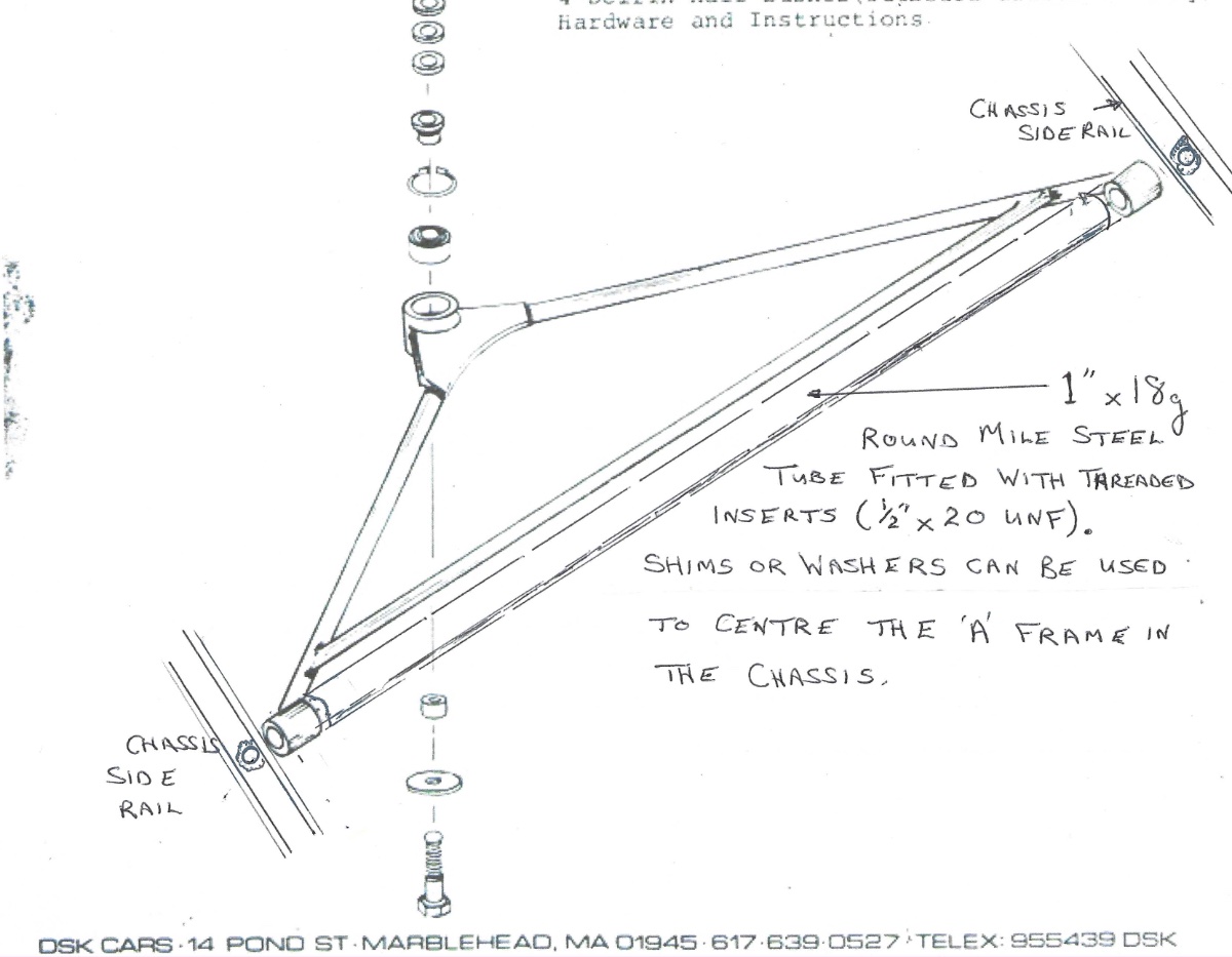
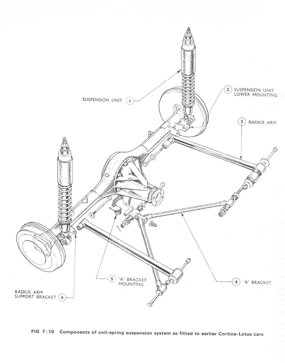
Hi MV8. These are the only diagrams that I could find. My thanks to David Kaplan for his series of bulletins, now posted on SimpleSevens.org (John D. thank you also), and to John C. and Scott (Iamscotticus) for their advice to post these. Image 1. This is the lower 'A' frame produced by DSK. It places the spherical bearing in the correct plane to prevent side-to-side movement of the axle without over stressing the bearing. When Caterham promoted the spherical bearing as a possible solution to premature failure of the rubber bushes, they placed the bearing in an upright plane (to fit their existing 'A' frame), and used bearing spacers and circlips either side of the bearing. I am not an engineer*, but I would think that this will place more stress on the bearing causing faster wear on the bearing ball and its housing, and I'm guessing that it was never designed to be used in this way? Len Terry on his Terrier racing car, located the spherical bearing in the same orientation as DSK. Image 2. This shows the tubular brace designed to connect the sides at the rear of the chassis, just behind the seats on a Series 2 or 3. As MV8 advised, it does not add any un-sprung weight, but does provide extra strength to the 'A' frame and the chassis in one go. It can be removed if required to return the chassis to as built. Longer bolts and perhaps washers or shims may be required to centre the 'A' frame. Note: The drawing should read 'mild steel' not 'mile steel'. Image 3. This is a diagram of the original Lotus Cortina method of locating the 'A' frame on the car. The swivel is located with rubber bushes, and provided with a grease nipple to lubricate the swivel. The diagram is from the Autopress Ltd. Ford Cortina 1967 - 68 Autobook Workshop Manual for the Ford Cortina 1300, 1500 and 1600cc including Lotus 1967 - 68 by Philip H. Smith. *Note: I am not a draughts-person or good at drawing, so please excuse the add-ons in image #2. Oh well! Cheers, Bill.
-
Caterham A Frames - check them as part of your annual maintenance
EdWills replied to Croc's topic in General Tech
Apologies, drawing would not load -
Caterham A Frames - check them as part of your annual maintenance
EdWills replied to Croc's topic in General Tech
Part 2. My apologies if I have gone on too long on this subject, but I forgot about an article I found in one of the Lotus Seven Portfolio books I have. In a magazine article from a U.K. periodical included in the Portfolio book, probably around 1969 or so, the author was advising how to recognize a 'genuine' Seven and what to look out for in the way of repairs and possible frame structure problems. He noted that some* owners of Series 2 and 3 cars made a fix at the location where the 'A' bracket attaches to the chassis frame just to the rear of the seats. They fitted a 1 inch x 18 gauge round tube with threaded inserts (1/2 inch - 20 UNF) in each end, and bolted this between the 'A' bracket ends with the rubber Metalastik bushes fitted to the ends of the bracket. Longer 1/2-20 bolts grade 8 or better (AN?) would be required, plus shims or washers to centre the 'A' bracket in the frame. (I purchased a packet of various thickness shims some time ago from Dave Bean with 1 inch o.d. and 1/2 inch i.d. - very useful). The 18 gauge hollow tube secures the ends of the A bracket to the rear of the chassis, and also adds some strength to the area of the frame just behind the seat squabs. As mentioned above, in order to save costs on the Series 2 (and 3 with an almost identical chassis frame), the tube fitted behind the seats at the bottom of the chassis on the Series 1, was removed on the Series 2/3. By adding the round tube between the front of the A bracket locations, it adds some strength to this area almost triangulating the tubing behind the seat back again. For authenticity, if it is required to return the car back to factory trim, the tube can simply be unbolted as it is not a permanent structure. *Note: I have never seen a Series 2 or 3 Seven fitted with this modification or viewed any photos of it, but in the Lotus Seven book by Dennis Ortenburger, he shows a Series IV with this modification added to the rear suspension. I do not know how many 'some' are, but the author of the article seemed to have knowledge of it! Bill F. -
Caterham A Frames - check them as part of your annual maintenance
EdWills replied to Croc's topic in General Tech
It was very interesting reading this link regarding 'A' frames, and also the technical notes from David Kaplan (of DSK). It has been well documented that, quote: 'Colin Chapman realized that the price of the Series 1 chassis frame was becoming too expensive to buy in. If the design could be simplified, the cost would be reduced. The original drawing by Ian Jones for the Series 2 is first dated November 16, 1959 but the model wasn't listed until June 1960. The 'A'-frame was not a Chapman invention, but on the Seven it was employed in an economical and effective way'. (paraphrased from Jeremy Coulter - 'Lotus Seven - Collector's Guide'). In Len Terry's book, he advises that the 'A' bracket layout that he incorporated on his Terrier Mk.1 'was inspired by that of the G Type ERA though the latter in fact had de-Dion suspension'. The ERA had the 'A' frame on top of the De-Dion axle, and the trailing arms were on the bottom. Terry overcame this by inverting the linkage to lower the roll centre on his live axle car.. "The A-bracket was ball-jointed to the underside of the final-drive housing. This variation has since been copied for several other cars, perhaps the best known being the original Lotus Cortina and later models of the Lotus Seven'. Len Terry worked as a draughtsman for Lotus during 1958 and 1959, then again at the end of 1962 to 1965 as chief designer. Note: The Lotus Cortina location for the apex of the A-frame had a swivel with a grease nipple, and used a spacer tube and rubber bushes inside the swivel where it attached at the axle bracket. When I had to purchase a new chassis frame from Arch/Caterham to replace my badly damaged unit (mid to late 1970s), it came with a new 'A' frame. The original had been braze welded, but Arch completely fusion welded my new 'A' frame. They had also machined the slots to take circlips to secure a spherical bearing if required. I've mentioned in another post how Caterham tried a couple of ways to secure the apex of the frame to the axle (ball joint, sliding ball joint), but a letter from their technical director advised that perhaps Chapman had it right, as - especially for a road car - the rubber bushes provided the necessary flexibility, providing the best suspension with this layout. This assumed that the rubber bushes would not be contaminated with oil or grease, and were kept at the correct tightness. I am not sure if the Ford axle suffered as badly as the Standard Triumph unit, thus the axle strengthening plate may not be as necessary? Comments please from those with a Series 3, without the steel strengthening plate or other mods added to prevent the Escort axle from twisting. One poster inquired why the radius arms on the Series 2 (and my Lotus factory built Seven Series 3, shipped to Canada) had the bend in them. According to Tony Weale, 'the Lotus built Series 2 Seven radius arms are cranked at their trailing end to provide clearance for the handbrake linkage of the Standard axle, and these parts continued for the Lotus Seven Series 3 though the handbrake linkage had moved'. No doubt Lotus had many spares of these, so used them up on the Escort axle cars. Caterham manufactured straight radius arm as replacements. Lotus also used cranked radius arms on the Series IV where they connected to the rear of the chassis frame. As you may note, all of my information comes from the many excellent books on the Lotus Seven by various knowledgeable writers. I purchased these books when they first came out as my car had been modified somewhat by the second owner (I am the third), and I wanted to know what was correct and what was not. These same books are now ridiculously expensive as it seems that they have not been republished. I really appreciate the input of the many knowledgeable contributors to this forum as well as the extensive library of lotus@se7ens.net originally started by John Watson. John D. and I have noted discrepancies in some of the books, but former Lotus factory personnel have put things straight on some of the queries we had. Bill F -
Thanks to those who contacted me. Bill F.
-
The 'Village' a.k.a. Portmeirion Village, is located in Gwynedd, North Wales. Originally Built in 1925 as a 'folly' it was under construction up to 1975 built in the Baroque style and now owned by a charitable trust. Accommodation is available on site if you ever want to visit there. Beautiful part of the country. EW
-
Hi All. Well, it looks like I lied, and my nose is starting to grow. I found two Seven America Road and Track road tests from July 1961 and September 1962 where both cars are fitted with the Lucas L1130 but no signal lamp bracket beneath the headlights (reproduction of the article quite hazy).. The signal switch on the dash was a substantial looking item, and possibly Holden still have these? Holden carry two types of L1130, one cast and one drawn. The drawn lamp is double the price. They also carry (or did) spare rubber mounts and bulbs for these as well as the L516. Tony Weale in his book Lotus Seven, Restoration, Preparation, Maintenance' advises: "That before 1979 two alternative types of Lucas separate sidelamps were fitted. The larger ones will be familiar to MG "T" owners, and the smaller ones are common with the Austin A40. Both types were listed for the Series 2, and although the smaller ones were common on Lotus Series 3s, some early Caterhams used the larger type". He goes on to say: "Provision was not made in the wiring harness for flashing indicator lamps until late in 1961, and the lamps themselves remained optional until standardised midway through Series 2 production". Tony Weale does not indicate when the signal light bracket commenced to be fitted beneath the 7 inch headlamp. 5 inch spot lamps were fitted prior to 1964. I have a photo of a 1959 Series 1 Seven where the car is fitted with a signal light bracket mounted underneath the 5 inch spot lamps. It is a pear shaped bracket and possibly of the owner's own design. I really like the metallic blue finish of one of the Sevens shown above. Lotus produced a number of factory fully completed Series 3 cars for export to Canada, and they were painted in metallic blue, as was the original Seven Series 3 introduced by Graham Nearn at his brother's pub. The second owner of my car repainted the car unfortunately. Cheers, Bill
-
Hi Henry. 100% correct, and the Lotus Seven Owners Manual shows both options. As I noted, I cannot find any road tests or photos that I have (there are tons more out there to blow my theory to bits!), where the car is fitted with the L1130s only.. Please note however, that John's Lotus Seven Registry incorrectly lists some of the lamps, flashers and sidelights for the Series 3 almost identical to the lamps he has listed for the Series 2. Perhaps for the U.S. as one poster has mentioned, the L1130 lamps were fitted without the lower flasher indicator bracket that became standard on later Series 2s and definitely on Series 3s. On early Series 1 and 2s, a narrow headlamp was also fitted and is shown in the manual. You are correct that the L516s were used in conjunction with either the L539 (Series 2) or L691 (Series 3) flasher indicators. So for the very early Series 2 cars shown in the photos, the L1130s would appear to be correct - if I mislead, my apologies.
-
Hi All. From the many photos I have in my collection, the 'torpedo' lamps shown in the photos above do not appear on any of the Series 2 or 3 Lotus Sevens that I could find. The usual fitment was the slimmer and more aerodynamic looking Lucas L516. These are still available from a couple of sources in the U.K.: Holden Vintage - www.holden.co.uk, or Stafford Vehicle Components - www.s-v-c.co.uk. Stafford are a tad cheaper, but both show U.K. Value Added Tax included that is normally removed for export (at roughly 16.67%, not the full 20% as charged in the U.K.). The rubber mounting pad and hardware are supplied with the lamp. Both companies still sell the different Lucas amber flasher/indicator lamps (both terms used for these) that were used by Lotus on the Series 2 and Series 3 (also red lenses for the rear of the car if needed). Note: Please see the Lotus Seven Register U.K., where John Watson has listed all the correct Lucas part numbers for the different electrical components used on Sevens. For the Lotus Seven Series 3, the L691 front and rear amber flasher/indicator was used, not the L539 that was posted on J.W.s site originally. The L539 was the flasher lamp for the Series 2. The L691 was also fitted on the front wings of the Lotus Seven Series IV. No one at the moment produces replacement Wingard (used pre 1965) or Thorpe P.T.675 rear tail/brake lights (August 1965 onwards), although one gent remanufactured Wingards for a while. I note the use of hexagon head bolts on the fibreglass wings/clamshells in a couple of photos. Lotus (and possibly Caterham) used slotted mushroom head bolts and nyloc nuts with the smooth mushroom head on the inside of the cockpit by the knee to hold the rearmost wing bracket, and the smooth head on top of the wings where they are bolted to the headlamp bracket and the rearmost wing bracket (with thin rubber washers under the heads). I have a few for sale in the parts for sale section of this forum under 'nuts and bolts'. I can get more if anyone is interested, or pass on the address. I'm not a business and have a lot on the go, so the info. is available if you want it. Bill (alias EdWills).
-
For sale are the following nuts, bolts or screws. A packet of: 3 - 3 B.A. x 3/4 inch long, new, unused, coated steel countersunk slotted head screws to attach Wingard rear lenses to their bases. Ages ago, I ordered a few of these for some Wingards that I had found, but only have the 3 remaining after the sale of the Wingards. These may prove useful for spares or to replace missing or damaged screws. Also included is 2 used nuts, washers, and screws from an original Wingard lamp base which may be helpful for sizing up replacements that may have become damaged. Recently I checked for distributors of B.A. screws in the U.K., and many now only sell even sizes. $6.00 Canadian plus postage for the packet. I have 3 sets available consisting of: 2 brand new ARP hardened chrome-moly washers, 1/2 inch inside diameter x 1.3 inch o.d. x 0.120 inch thick with black non-rust finish, along with 2 brand new military grade AN365 1/2-20 UNF threaded Nyloc nuts (rated at 125,000 psi). These are for the inner ends of the Triumph Herald upright to secure the stub axle to the upright. (note: These are for the early type of upright with a separate disc brake bracket, not the later type that incorporated the calliper bracket on the upright). The washers are the correct size to fit the axle, and the end of the upright. The nuts - when fully torqued - should leave necessary thread showing. Note: Using ordinary mild steel flat washers may be bad practice, as torquing non-hardened washers to 55 - 60 foot pounds of torque with standard 1/2 inch Nyloc nuts of 3/4 inches across the flats, can severely distort the washers (it can cause actual 'dishing' of the washer), resulting in a lower torque value than recommended, thereby compromising the safety of the part. $12.00 Canadian plus postage for 2 new washers and 2 new Nyloc nuts. Mushroom slotted head bolts with nuts (14 of each available). These are fine thread M6 x 60 mm long with a 15 mm diameter slotted mushroom shaped head. The equivalent is 1/4 inch thread x 2-1/2 inches long x just over 9/16 inch diameter head. Lotus used these particular bolts to attach the front cycle or flared clam shell wings and stays to the car. These are slotted head as per Lotus specs, and come with correct fine thread Nyloc metric nuts (either regular or shorter height if preferred). Note: These bolts are not what are sometimes referred to as carriage or coach bolts (or fender bolts?). The carriage bolt does not have any holding method in the head, but instead has a square shank under the head. Most of this type have coarse threads either Imperial or Metric. Lotus probably chose to use mushroom head bolts with the head inside the cockpit to avoid scraped knees or hands. The use on the cycle wings or clam shells was for appearance sake, looking much smoother than say a hexagon head bolt. These metric mushroom head bolts exactly fit the welded spacer tubes on the side of a Caterham chassis, and also fit the loose spacer tubes used by Lotus to secure the rear most wing brackets to the chassis. To use these bolts through the ally or fibreglass clam shells, rubber washers should be used to cushion against the fibreglass (not supplied) and not overtightened leading to cracking of the glass.. Set of 4 nuts and bolts $8.00 Canadian plus postage, but I have up to 14 nuts and bolts if extra are required. I can be contacted via this forum, or by clicking on anglocanadianlotus7.ca, or by checking Simple Sevens.org where I also have some items for sale. Cheers, Bill F.
-
Hi Dreamer. According to a January 1981 article in Motor Sport magazine (U.K.) Caterham were planning to use a 4 link with Panhard rod set-up on their basic 7 and Sprint models using the 1600 Crossflow for 1981 onwards cars. In the same article, a road test of the Caterham race car prepared by Chris Meek with engine constructed by Clive Roberts mentions an upgraded rear suspension, but does not detail which type of rear suspension (i.e. 'A' bracket or 4 link with Panhard) was used on their race car. Note: I mentioned the 1975 Modsports car built by Caterham for David Bettinson. I wrongly noted that the car had 18 pounds of metal removed after it had been strengthened. This is totally incorrect as 18 pounds of tubing was actually added to strengthen the chassis making it over 4 times stronger, but 14 pounds of trim material was removed, making the car only 4 pounds heavier. As I mentioned above, it had a 4 link with Panhard rod rear suspension. In other U.K. magazines featuring Caterham 7s that had been adapted for racing by their owners, some competition bodies required an original type of 'A' bracket at the rear. Some referred to using a ball joint at the axle location, and one referred to a sliding 'A' bracket, which appeared on Rob Cox Allison's 'Black Brick' series of racing cars (I am fortunate to have an original blueprint of this set-up). The Motor Sport Jan. 1981 edition also mentioned that Clive Roberts had experimented with a turbocharged 7, so again, David Kaplan was ahead of his time once again. EW