anduril3019
-
Posts
157 -
Joined
-
Last visited
Content Type
Profiles
Forums
Store
Articles
Gallery
Events
Library
Everything posted by anduril3019
-
Any chance the release bearing is returning too far due to engine vibration? Not sure if it's possible with a concentric release, but I had something similar happen with a standard release bearing. Everything seemed fine after bleeding, but after running for a little while, the clutch wouldn't disengage. Turned out there was a stiff spot in the slave cylinder, the external return spring on the slave cylinder that keeps tension on the fork and pushrod seemed fine while cold, but it was actually stopping at the stiff spot in the cylinder. When hot and vibrating, the plunger would move past the stiff spot, returning farther than normal, leaving a gap between the clutch and bearing and not enough travel to disengage. Also check your upper pedal stop (whatever is stopping it, master cylinder, chassis, etc.) make sure pedal is all the way up when adjusting everything.
-
That looks better!
-
Is that the before or after shot? Just asking because typically you want to back the grub screw all the way out, and then the two parts of the clamp will tighten without a gap between them. Contact, or near contact, with the flat of the shaft is what keeps it from rotating. The grub screw is then tightened, and it's main job is to keep the shaft from sliding in and out, except in an accident. Again, that's just the typical fit, yours could be different.
-
Have you decided to get the head surfaced? The area where the gasket failed definitely looks suspect. (based only on the photo, of course) Back to the can of worms theme, you might as well measure your compression ratio while you've got it all apart and determine if surfacing the head will affect it. It may affect it negligibly, but you won't know if it matters, unless you know where it is currently. General note: All the advice and collective knowledge your getting may be overwhelming (or it may be just what you were looking for?), but it's all the small details that help eliminate potential failure points when it's all back together and you turn the key. You could potentially yank the head off, clean it all up, put on a new gasket and be good to go. It might work, and get you on the road, or it might not, and you'll be right back to where you started, or worse off, and trying to troubleshoot again.
-
A drop of oil or assembly lube on the threads and under the bolt head will also do the job. What you don't want is any collected oil in a blind hole, it creates a nice little hydraulic press as you screw the bolt in.
-
Not impossible, but pretty tough to snap a head bolt unless they have significant rust or other damage. If they've been stretched beyond their elastic limit by over-torquing, let's say you're trying to reach 75 ft. lbs., at some number below that, like 60 ft. lbs., you will continue to turn the bolt, but the torque reading won't get any higher, it will stay at 60 (or even drop slightly) as the bolt continues to stretch instead of providing more clamping force. Any engineers out there, feel free to correct my terminology (and add depth) in terms of yield, deformation, stretch, elasticity, torque angles, etc. With all that said, Ford pushrod head bolts are pretty stout for the job performed. Twincam head bolts are a little more delicate, as are the heads.
-
Sorry for the can of worms, but how does the block deck surface look? I'm guessing it's corroded where the failure is.
-
After removing that gasket, you'll want to carefully inspect the head surface where it failed and around other water passages that look corroded. Some rust/corrosion is to be expected and acceptable, depending on how it encroaches on the sealing surface. But try and determine if it's the head or the gasket (or both) that failed. Depending on how the new gasket matches and seals around the water passages, you may be ok. But the sealing surface around each cylinder needs to have zero corrosion. The spot where your blow out is looks a little suspect from that photo. Not likely that you'll need head bolts unless you aren't able to bring them up to torque. But you should chase the holes in the block with a tap and clean them well. Completely tape off the top of the engine to keep debris out, and gently run the tap in each hole, just to remove dirt and rust, you shouldn't be removing any metal. You might be able to accomplish this with a wire tube brush instead of a tap, but in the end what you want is for the head bolts to easily go all the way in and out by hand. With each hole, thread a bolt all the way in and measure from the block surface to the underside of the bolt head, make sure this measurement, minus the gasket thickness, is less than the thickness of the head. This may be overkill since all these components were working together, but it's nice to know what you have. Heads can get swapped or milled too thin over time, resulting in head bolts being too long for a particular head and bottoming in the holes. Worst case is that they just barely bottom, causing the torque to look good, but not actually clamping the head sufficiently.
-
When troubleshooting, don't forget to use the tools you've got at hand, the ones attached to your body. You're nose is one of the best! I'm not advocating for you to inhale exhaust fumes ... but, burning oil, burning coolant, and "burning" water will all have very distinct smells.
-
Bean is always a good source if they have one. Fel-Pro for a 1970-72 1.6 L Pinto is a good solution that's easy to find at a lot of other suppliers. (I'm assuming you aren't running a large bore engine) This will fit your 1500, same head gasket used for most of the various iterations of this engine. https://www.pegasusautoracing.com/productdetails.asp?RecID=29958
-

New 7 Owner Initial Questions
anduril3019 replied to Randy Flowers's topic in General Sevens Discussion
Maybe a dumb question, but... Have you looked at all into the possibility of widening your pedal box? On the clutch side, is that an interior panel, or the inside of the bodywork? If it's an interior panel, you could remove it or cut it back. On the gas side, how much clearance do you have between the panel and the transmission? If you can figure out how much engine movement you may have, you might find a little space there to either form a recess in the panel for a little bit of foot room, or make an entirely new panel., then adjust the pedal spacing accordingly. There may not be much room, but with what you've got, even if you can pick up 1/2" overall, you're going to notice it. -
I'm trying to imagine what 24 cylinder car you have.
-
Did you have the same (or other) problems before the rebuild?
-
Phil Bass, aka Cortina Phil, in Southern California, is a great source for used parts. I realize you already own a used clutch! However, he's also good at mixing and matching and figuring out what you can do with whatever you happen to have in terms of transmission, input shaft, bell housing, flywheel, clutch, etc.. Might be worth a try: cortinaphil@cox.net
-
UNC and UNF Bolt specs. for a Ford Crossflow engine
anduril3019 replied to EdWills's topic in General Tech
I'm interested in the list. I'm slowly collecting parts to build a 1700 pre-crossflow on a 7llM block. -
Where is the technical library?
anduril3019 replied to Cueball1's topic in General Sevens Discussion
On the top menu go to: Browse > Downloads https://usa7s.net/ips/files/ More obscure or specific tech help can be found buried in discussion threads by using the search. -
The semi-circle sealing surface (say that three times fast!) at the rear of a lip seal pan is approximately 5" diameter, on a rope seal pan it's about 4" dia., very roughly speaking. I don't have a rope seal to measure, but it's significantly smaller.
-
Sent you a PM
-
Awesome! I did the same for my daughter's troop. She's 35 now and can change oil, brake pads, and bulbs! Sounds like you may have inspired a few future enthusiasts. Good luck.
-
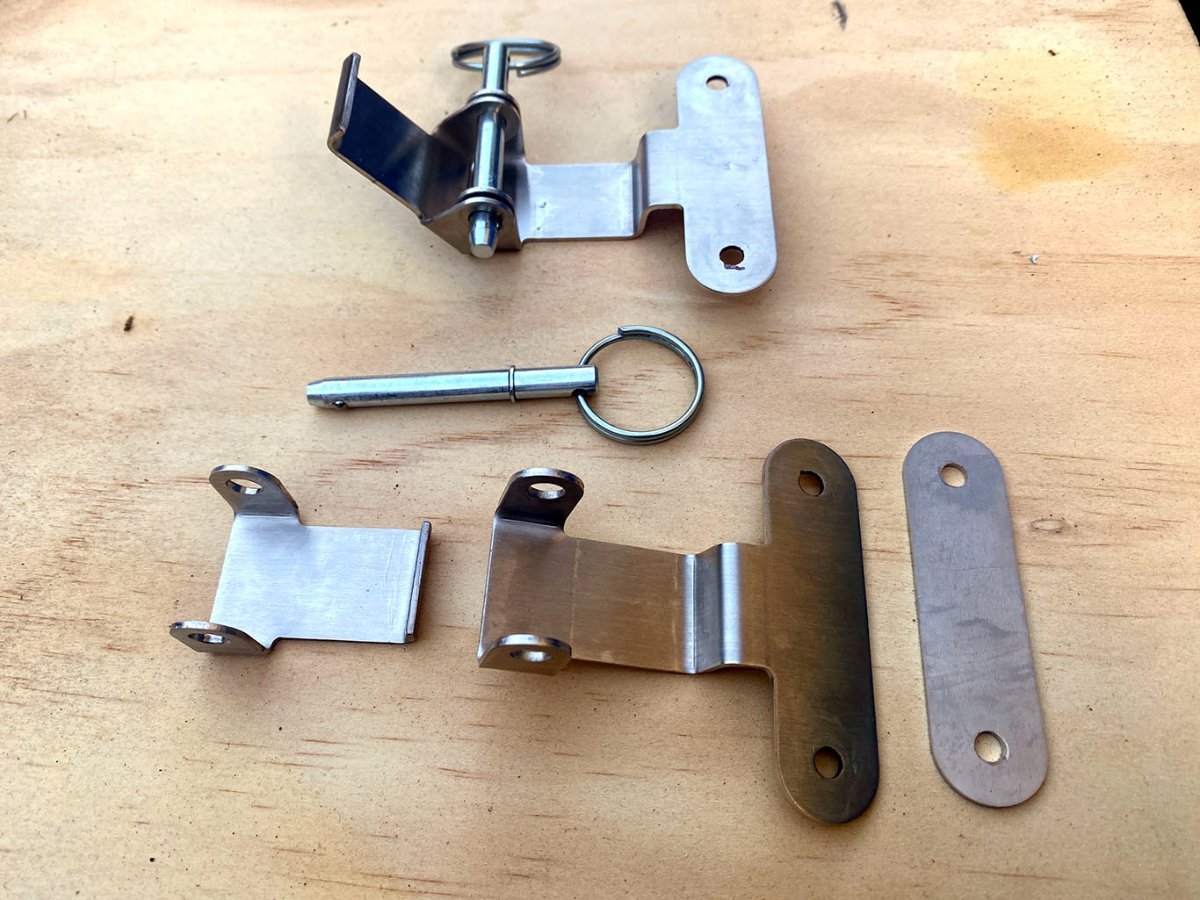
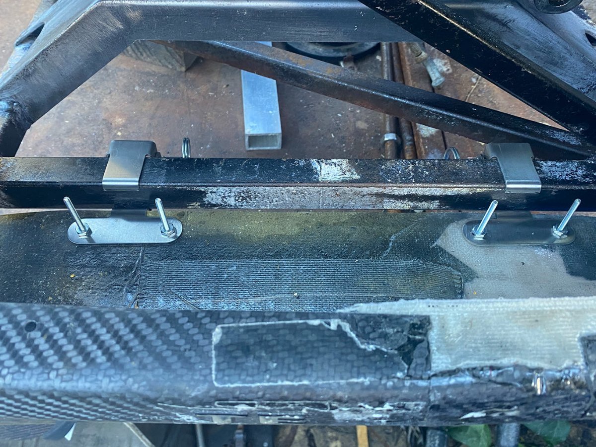
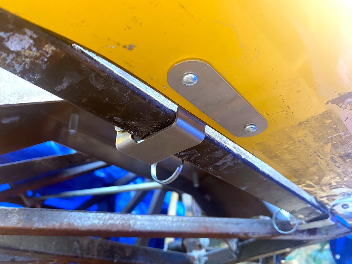
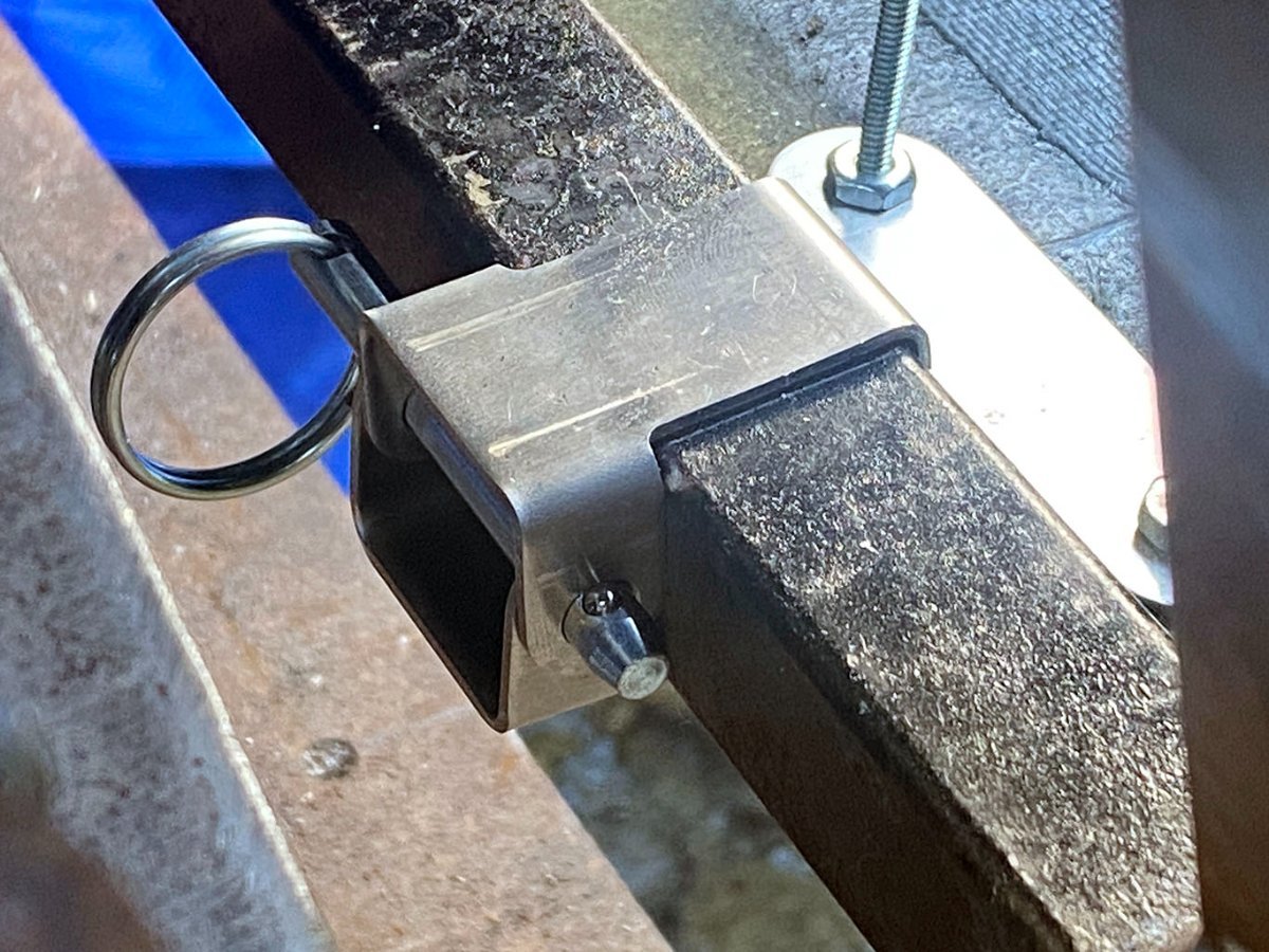
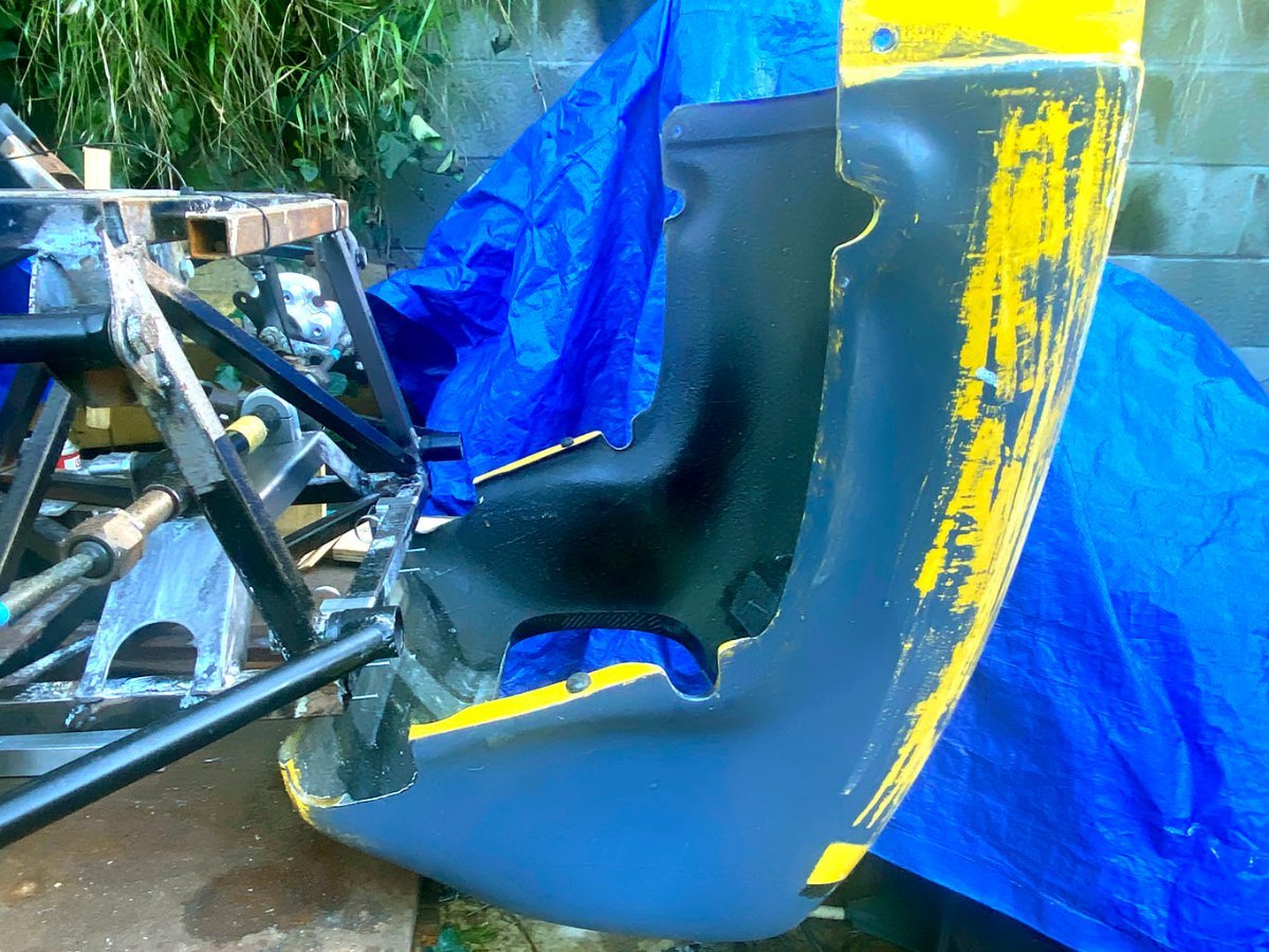
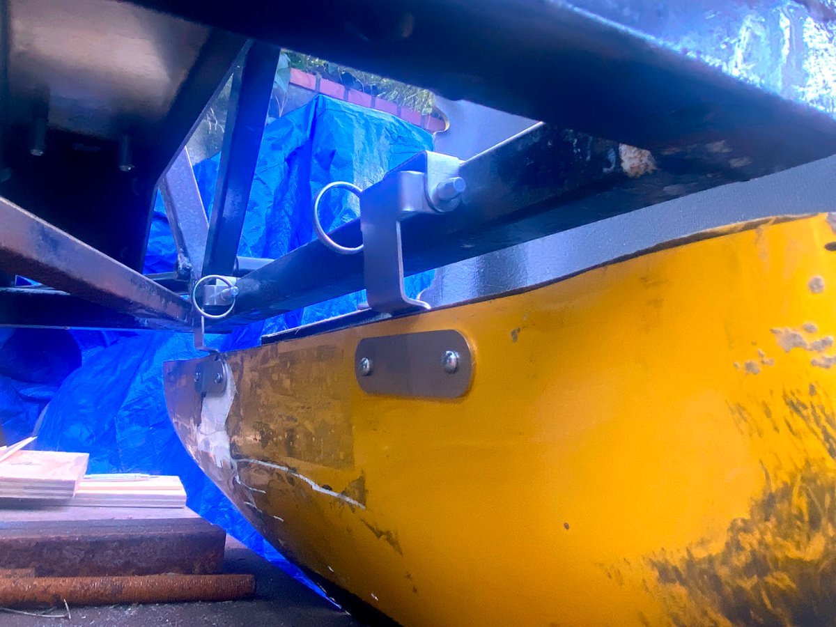
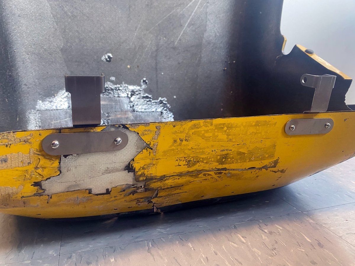
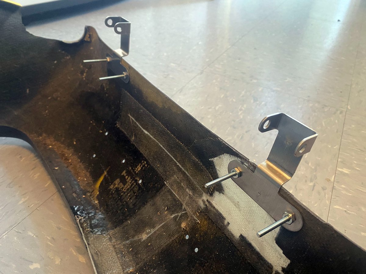
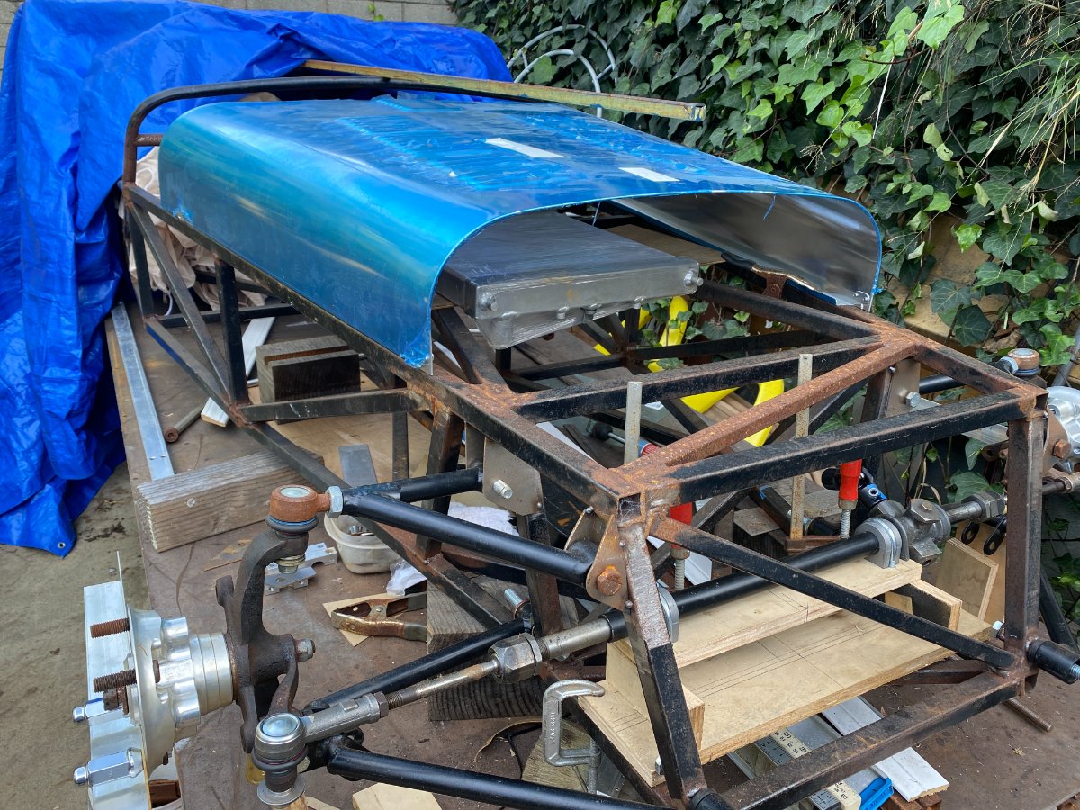
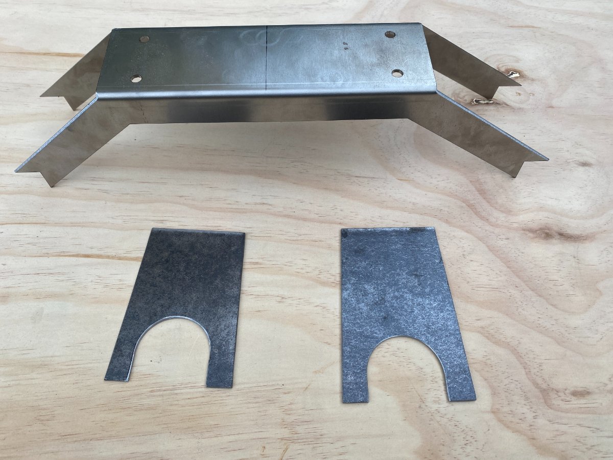
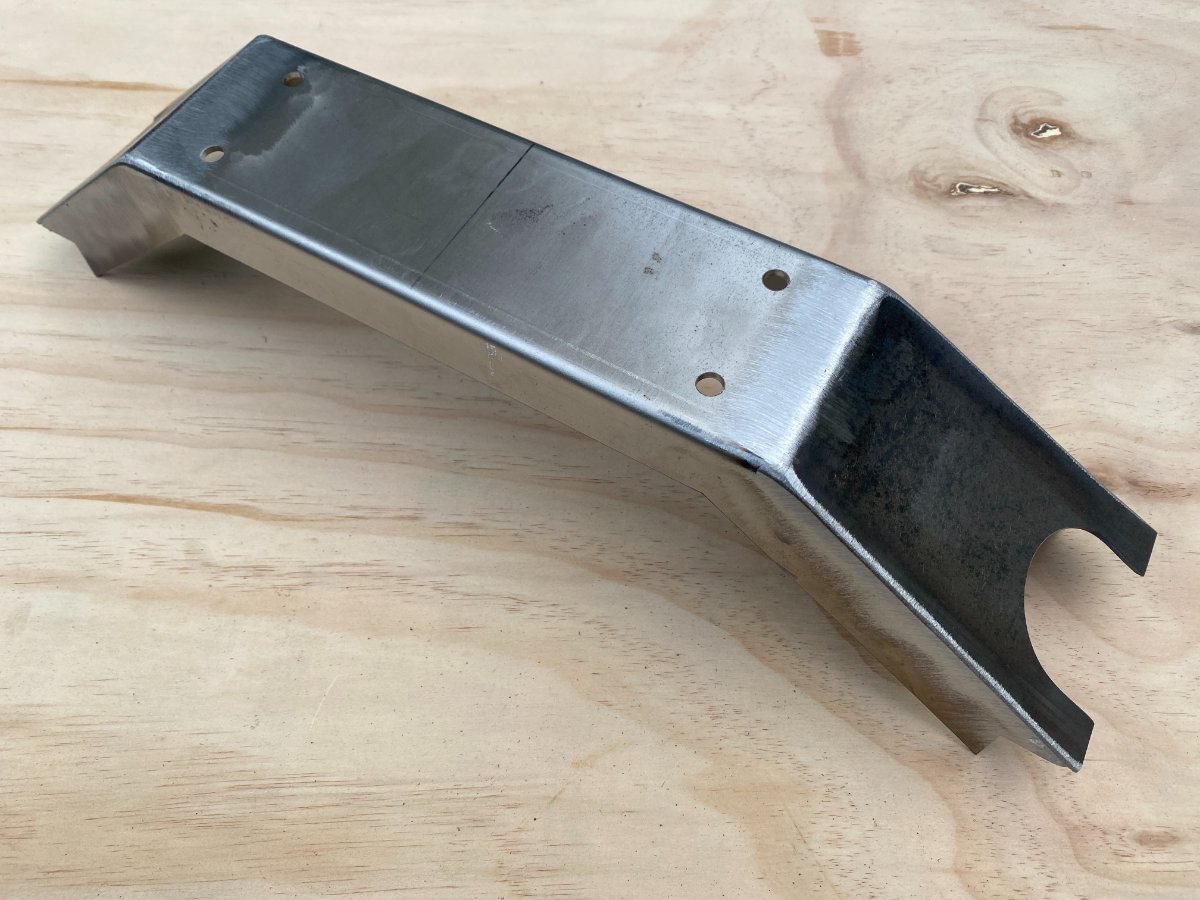
Regarding the lower Dzus fasteners, I'm experimenting with hinges and a tilt up nose. It needs a little finesse, but so far I'm liking it in concept. Part of the trick is getting it to pivot in the right place to clear everything as it swings open, and not have the pivot points hanging below the frame or nose where they are exposed to dirt and damage. The pins are easily removable, so the nose can still be completely removed if needed. The frame half of the hinge will be screwed to the frame. On the top, I can still use the standard Dzus method, or I may try just using small alignment pins and allowing the bonnet to do the hold down work. I'm going to add a clip-on check strap on either side to keep it from hitting the ground when open. I'll probably reinforce the nose at the mounting points. The hinge parts are 16ga. stainless from SendCutSend. Pardon the nose condition, it's a work in progress. It was mostly held together with tape when I got it, and I'm slowly working it back into shape. Anyone recognize it, by chance?

-
Unappreciated compliments
anduril3019 replied to Vovchandr's topic in Politics, Religion and Controversy
My assumption (stepping into dangerous waters right off the bat!) is that this comment was simple hyperbole, or reductio ad absurdum, or something like that. To which I might have replied, "Touché, I see your point!" Anyway, I thought the tire jokes were funner. -
Unappreciated compliments
anduril3019 replied to Vovchandr's topic in Politics, Religion and Controversy
Kind of a "tired" reference at this point. -
COD (Comment of the day)
-
Good tip on the rust, I'll hit it before it gets out of hand. Re. the trailing arms, if I was doing it again I'd probably do them in line with the outer chassis rails to pick up a little bit of cockpit width. As it is now, it's good incentive to finish the project before I'm too wide to fit!
-
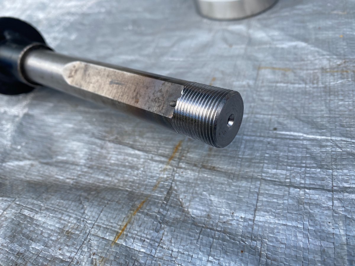
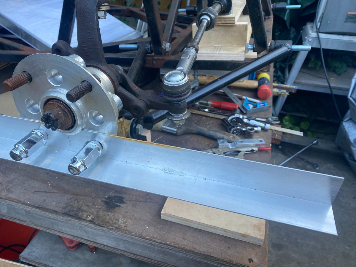
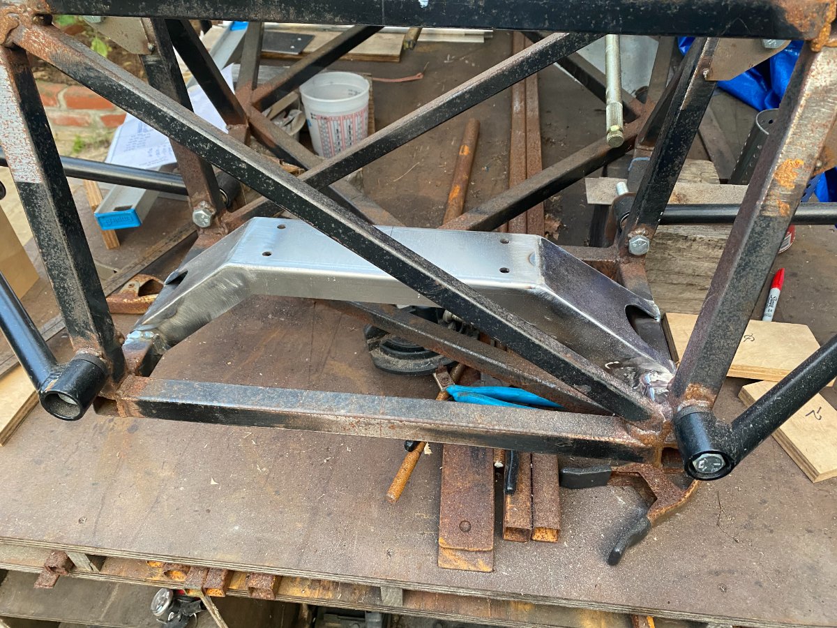
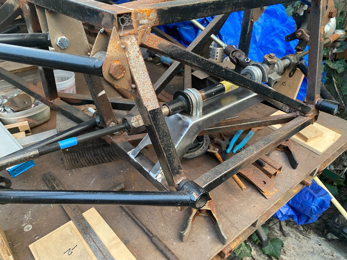
A little more progress... Steering rack mount. I did some mocking up of steering rack placement. Without working out the geometry, I was hoping my Spitfire rack would be acceptable unmodified. Bump steer turned out to be pretty significant, which I guess I could have figured out ahead of time! So I ended up having the rack shortened based on my Vsusp dimensions. I had a local machine shop cut the shaft, weld up to fill the machined flat and re-thread the end. Rack tube was cut and re-welded, leaving the bushing in place. With the shortened rack, I started dialing in the height by set toe at 0" at ride height, then measuring at 2" of bump and 2" of droop. Not as sophisticated as dial indicators at multiple intervals of suspension travel, but at least it's showing me extremes at this point. Once I got it close, I started testing with .050" shims. The best I could do was to get it similar at full bump and droop, ending up at about 1/8-3/16" total toe out (difference at front and rear of tire centerline). So with those numbers I decided to install the rack mount a little low to give me room for dialing in with more precision at final assembly. Ackerman at 10° of steering on the outside wheel results in +1°-1.5° on the inside wheel. Radiator mount is next.