papak
-
Posts
483 -
Joined
Content Type
Profiles
Forums
Store
Articles
Gallery
Events
Library
Everything posted by papak
-
It seems so.
-
According to the Subue forums, the viscous unit is sealed and non-repairable. It is filled with a silicon based lube with unique shear qualities. The diff itself uses GL-5. In my case, it seems as though the silicon stuff has been fried.
-
My Birkin uses a Subaru R160 viscous LSD. While at the track a couple of weeks ago, I lost about 90% of the forward drive in a 3rd gear sweeper. It was initially felt like a burned clutch (but on recollection, there was no “burned clutch” smell). After removing the engine, the clutch, slave cylinder and spacing criteria all seem spot on. After eliminating the clutch, the only remaining culprit seems to be the diff. When I initially built the car, I thought that a viscous LSD would be sufficient for the motor (2.3l Duratec with ITBs, 9.7:1 and Stage 1 cams, maybe 180-190 hp). I’m still trying to figure out a productive way to check the LSD. When the driveshaft is turned, both rear wheels rotate in the same direction as they should. The question is if the do so under load. I was able to drive the car into the garage from the trailer but it didn’t feel like it was fully connected. Not sure quite how to describe it any better than that. Any ideas?
-
Unless you are using huge injectors, the Duratecs run at 42-43 psi.
-
Get a thread gauge and measure what you have. Try [boltdepot.com] as they offer a wider range of metric sizes and quality. I've used them in the past for unique fitments.
-
I have an XS Birkin in LA that you are welcome to try. It is cavernous compared to an S3 but the pedal box is the most rewarding difference. PM if you are interested.
-
I instructed for PCA in the Northeast years back and for POC when we moved to California. It was a fatality during a DE at Lime Rock that brought in the mandatory seat back brace. We really tried to control the events by being very conservative when releasing drivers to "solo". We also restricted the passing zones and often held mandatory mid-day drivers meetings to review the mishaps of the morning sessions. With both organizations, one of the biggest points of discussion was the level of automation in the new cars. If those electrons ever stop holding hands in a 996 going into Turn 8 at WSIR, you better hope the roll bar is sturdy. We also tried to build the run groups by performance capability as well as driver ability. we were pretty strict on safety equipment as well. Once running with POC on the West Coast, I was one of the first in our group get a HANS device. I took a bit of ribbing for wearing it for DE events but it soon took hold. I happened to be in Atlanta on a layover and went to Jim Downing's shop to scope them out. He was starting to make them to order for a number of pro drivers. After a brief conversation, I placed my order. I understand the new ones are much more refined and lighter. The thing with instructing is that if the more experienced members don't pitch in, you are left with no instruction at all. It helps feed the pipeline of drivers who may eventually move up to club racing and that, to my way of thinking, is worthwhile. I would rather have a hand in the process than trust to fate entirely. Just my $.02
-

2.3 or 2.5 Duratec/MZR in Birkin S3
papak replied to JeffersonRaley's topic in General Sevens Discussion
The Raceline dry sump and wet sump both have nearly the same depth below the block. No help there. They both fit inside the Birkin skid plate. After driving mine for 2000 mi., I would be reluctant to NOT use the skid plate. I'm pretty careful and I still have some dents in mine. The 2.5 is the same height as the 2.3 (the bore is larger on the 2.5). The front of the T-9 ends up being the low point. You could probably grind off ¼" or so. Tom Carlin ((970) 376-5188) can probably supply the correct engine mounts. He also offers a lower cam cover that keeps everything below the aft edge of the nose. -
As you can see, I haven't fully mastered attachments.
-
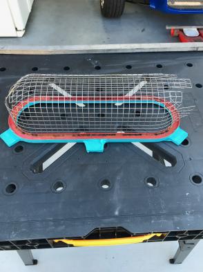
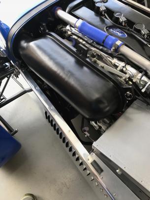
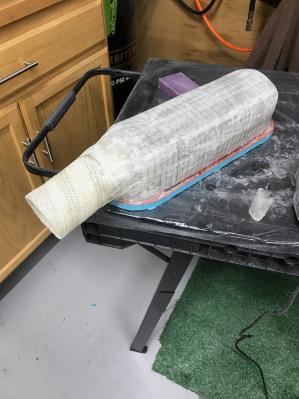
I have been interested in improving the performance of my 2.3l Duratec with an eye toward cost effectiveness. Toward this end, I decided to fabricate a cold air induction system. It seems that the consensus is that you gain 1% for each 10 degree drop in inlet temperature. From a closer look at the physics, this relationship varies with the temperature range but for our purposes, that ratio is reasonably accurate. I found a very nice airbox on the Jenvey website for $275 and another nice one on the SBD site for $592. The several others I found are in that price range. Ouch! I had an old ITG “sausage” type filter sitting in the shop with worn out foam on it. This would normally cover the four 48mm ITBs with 50mm tall trumpets. I stripped off the foam and found that the underlying stainless steel screening is epoxied to the base. I opened up the front end of the screening to accommodate a 3” fiberglass tube. I then used an ultra fine fiberglass tape normally used for drywall seams to cover the outside of the shell. This stuff works great as it has a light adhesive on one side and is easily trimmed with scissors. I used some expoxy saturated mat on the inner surface. Once all of this set up, I hit it with some 80 grit. This was followed by a fair amount of lightweight filler in several thin layers interspersed by sanding. Using a couple of manilla file folders, I determined the outline of the necessary blocking plate to fit the drover’s side of the nose fairing opening next to the radiator. This was transferred to aluminum sheet, cut and bent as necessary and mounted to the radiator mounting bracket. This was then trimmed to accommodate a 3” aluminum tube. The tube was mounted so that it extended in front of the radiator. I mounted a foam “sock” type air filter (Uni NU-2483ST) in the front of the tube (treated with K&N filter oil). This filter (or similar) can be found in many motorcycle or ATV shops. Aside from the potential power gain, the impact on engine sound is noticeable. This cancels nearly all of the intake noise and consequently, makes the exhaust sound crisper. I considered fabricating a rubber baffle to surround the entire radiator (as in light aircraft installations) but the present cooling system works great as-is and the under-hood temps are not uncomfortable. There are 152 louver cut into the bonnet of the Birkin. This, in combination with the airflow around the radiator, eliminates the transmission tunnel heat issue entirely. http://www.usa7s.net/vb/attachment.php?attachmentid=15275&stc=1http://www.usa7s.net/vb/attachment.php?attachmentid=15273&stc=1http://www.usa7s.net/vb/attachment.php?attachmentid=15274&stc=1 In the end, the total cost was under $100.

-
Birkin XS - side by side comparison to a Caterham CSR
papak replied to Croc's topic in General Sevens Discussion
My XS ended up at 1337# with driver, basic fluids, mounted spare and 6 gallons of gas. With the 2.3l Duratec and the factory skid pan, I have exactly 2" of ground clearance. I just finished installing a cold air box over the trumpets. I had an old "sausage" filter with worn-out foam. I removed the foam and glassed the SS wire frame, forming a 3" tube on the front end. A flexible duct with a foam "sock" type filter runs up next to the radiator. Less induction noise but a bit more power. Now I notice the exhaust note more. -
You might try John Esposito at Quantum Mechanics in Oxford, CT (*(203) 463-8299). He has been at it a good while now and probably knows who is around and worthwhile. No email.
-
Just bought a Birkin. Need transmission advice.
papak replied to PalaceOfFun's topic in General Sevens Discussion
I would second the recommendation for John at Quantum. Great guy, a straight shooter. -
Not sure if my pm got through. kpkehoe@ca.rr.com
-
I recall that when I originally went through the motor, I fully disassembled the tensioner to make sure everything was perfectly clean. I also installed new plastic guides. Simple but effective design.
-
When i rebuilt my motor, (out of a 2008 Ranger), I acquired a Focus front cover for just that reason. If I can figure out the idler retraction, I'll feel better about moving forward. Kevin
-
That’s a very helpful guide, Andy. A real confidence builder! Kevin
-
This is in the “consideration” stage right now before I seek a spousal spending authorization. I’ll take a close look at the link. The Stage one cams currently in the car only have 1500 miles or so on them. I would venture that another set of new cams would not be likely to need new buckets but I would certainly check them. On a side note, I have pulled the front cover with the motor in the car. It’s a pain in the ass to do it by yourself as I did. I actually acquired the tool to hold the crank pully. I would have assistance this time around. I’ll keep the thread updated if I move ahead with this. Thanks for the feedback.
-
Can the cams be changed in a Duratec with the motor in the car? It seems to me that the only real question is the chain tensioner.
-
You will have to get them from Tom. They start out as the unventilated front rotors from a ROW ‘98 Golf 1600. The backside is then machined down to a nominal 10.2mm (as I recall, the minimum rotor thickness stamped on the rim) from 12.5mm in order to fit within the caliper given the hub dimensions. The good news is that given the weight of the car and the fact that you will invariably have more front brake bias, they will probably last the life of the car.
-
I'm looking for a serviceable top cover for a Ford T-9. I keep getting a fine mist on mine through the vent hole in the cover. I want to try welding a bung in it's place to add a vent line. I just want to minimize my downtime as well as not having to order one from England. NOTE: I have a plug welded into the right front corner for dipstick/fill access. I swapped in a ⅜" hard line with a breather on it. Due to the mystique of fluid dynamics when underway, there apparently is a steady stream of lube aimed at that corner. I lost about ⅓ liter in an hour's driving! I spent yesterday cleaning up the mess and re-installing the plug.
-
This is then basics of the testing procedure used by the BAR (CCR 1036): - Indoors or outdoors, flat surface, no sound reflecting surface within 10' of any part of the vehicle. - The microphone shall be at the same height as the center of the exhaust outlet but no lower that 8". - the microphone shall be placed parallel to the ground, 20" from the nearest edge of the exhaust outlet and 45 degrees from the axis of the outlet. - engine at normal operating temperature with the transmission in neutral. The measurement will be taken at ¾ of the maximum RPM or at 3000rpm for pre-1972 cars where there is no maximum rpm data available. - Not to exceed 95db!
-
I was speaking to a couple of fellows at the Gardena C&C yesterday and the topic of noise limits came up. Apparently, California introduced a new policy as of January 1st, 2019. The new limit is 95 db as "observed" by a law enforcement officer. Instead of the old "fixit" $25 ticket of yore, the law now requires the issuing of a ticket between the minimum ($197) up to over $1000! The officer will have no testing equipment upon which to base this infraction. There is no provision for pre-certification either. Once you have paid your fine, you can make an appointment with a BAR (Bureau of Automotive Repair) station for testing (this is where you took your car for it's emissions waiver as the final step in the SB100 process). Only they can issue you a certification of noise level. There is a charge (undetermined) for this test. Take the certificate (presuming you passed) and your receipt back to the court clerk for reimbursement. You can dig into the BAR website for the testing criteria. There are various db apps for Iphone and Android devices. Most manufacturers cars rarely exceed 75 db. There are separate rules for motorcycles. I know of a couple of fellows currently changing mufflers on cars like ours. I'm testing my Birkin ( 2.3l Duratec) tomorrow and will post the results. My understanding is that this is pretty discretionary for the cops. It is most likely intended to give them a another tool for dealing with street racers and ___holes. At this potential cost point though, it pays to be aware and prepared.
-
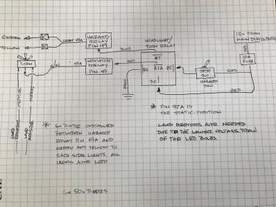
One of the issues I ran into when constructing my Birkin was the electrical system. I realize that it was designed in South Africa to comply with the requirements of a variety of countries while meeting cost considerations. In particular, I didn’t like the plastic rocker switches. Neither was I happy with some of the gauge locations. After living with the car for over a year after completion, I decided to do something about it. I ended up cutting a new instrument panel from 14g aluminum sheet using knockout punches (3 1/8” and 2 1/16”) as well as step drill bits. This allowed me to use toggle switches to replace the rockers. One of the problems that arose was finding toggles that would function the same way due to how the car was wired. I have now investigated nearly every toggle switch on the internet and none, to my knowledge, fit the bill for replacing the rocker style hazard switch. The real issues centered around how the indicator and hazard lights are wired. I ended up reconfiguring the wiring to use a 5 pin relay to switch the power supply between the indicators flasher and the hazard flasher. Since I have committed to running Brooklands windscreens, I could utilize the existing windshield demister relay. I am attaching a schematic as well as the following description of the process. These instructions are unique to the Birkin but describe a strategy that could be applicable to any kit car. Both the indicator lights and the hazard lights each use a 10a fuse. This modification eliminates both and uses the windshield demister slot to hold the 10a fuse for the new circuits instead. Proceed as follows: Remove the battery and scuttle. Label the cluster of connectors for each existing switch clearly (take pictures as well). Remove the relays and the relay cluster. Note that there is very little slack in the wiring harness. The relay bases separate by sliding apart front to rear. 4. You will need an extraction tool to release the connectors from slot 87 and 87A from the demister relay base. Slide an inch or so of heatshrink over the connectors and reduce it to protect them. 5. Perform the same task on the 49 slot of the bases for the indicator and hazard flashers. 6. Connect the wires from the old demister switch to the two poles of the new toggle switch. This switch now controls the old demister relay (pin 85). 7. You now need to fabricate two lengths of 16 or 18g wire of a sufficient length to run from this relay to the outboard flasher bases. You will need ¼” “Ford" female spade connectors (I found mine at Pep Boys). These connectors have a small retaining tab on the back to hold them in place in the base. 8. Connect slot 87A to indicator flasher slot 49. Connect slot 87 to hazard flasher slot 49. 9. Verify that the existing G/w wire from indicator slot 49A runs to the center pin on the directional switch. 10.The hazard output (49A) connects to all four indicator lights and treats them as one. We need to maintain the separation of each side in order for the directional to work so we need to install a diode in both the left and right circuits. Think of it as a one-way check valve for current. You will need two 6a50v diodes (Maybe you could use smaller. I’m no electrical engineer.). I picked up a small “project box”, about 1 ½” x 2” to house and protect the connections. The ends of the diodes with the stripes are mounted toward the light bulbs. The other ends are soldered to the grey wire (12v regulated feed) from hazard flasher pin 49A. This connection is located near the original harness location about mid dash. The other ends are soldered to the green and yellow wires as appropriate to segregate the signal. Drill holes in the ends of the box as needed. I lined the box with a thin layer of foam and secured it to the existing harness bundle with a ziptie. Notes: Continually verify continuity as you trace wires. I carefully soldered all connectors and covered them with heatshrink tubing. If you change over to LED tail light bulbs, use CANBUS bulbs. They will correct for the reduced load of the LEDS to reduce hyper-flashing. If the turn signals flash together, you may still need load-reducing resistors in the circuits. http://www.usa7s.net/vb/attachment.php?attachmentid=14952&stc=1
-
The worst part of rebuilding one of these is that the manufacturer never intended for it to be rebuilt. No key ways, etc. Drill out the plugs from the oil journals and tap them for brass plugs. It’s the only way to assure that they are clean.