Rosteri
-
Posts
179 -
Joined
-
Last visited
Content Type
Profiles
Forums
Store
Articles
Gallery
Events
Library
Everything posted by Rosteri
-
We also lasered a scale for the ignition timing mark to the alternator pulley. And the engine build was ready!

-
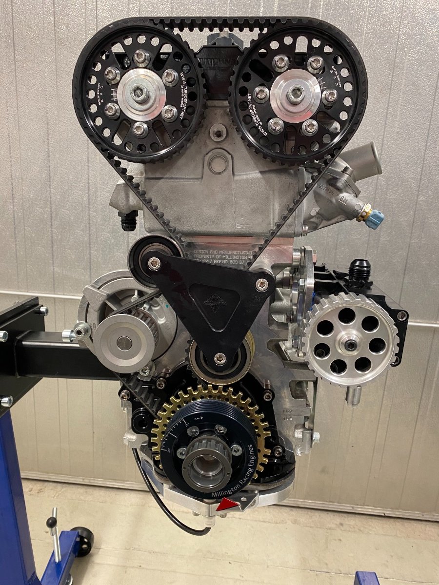
C20XE engines have several iterations of the timing belt - the early ones used a short belt (141 teeth) with a round tooth profile and the belt was tensioned by rotating the water pump, while the newer ones had a longer belt and tensioning pulleus. These tensioning elements connect to the metal timing belt cover, which I obviously no longer have in place. Water pumps have not just different tooth lengths, but they have also 21 or 25 teeth and different width belts. Finding the right combination was really difficult, so here are my numbers. Cambelt: Bosch 1987949091 Original fixed pulleys: SKF VKM 25211 (usually 2, but I used only 1, more on this later) Water pump: Magneti Marelli 352316170849 21 teeth, round shape But the belt didn't fit, it was too short. I guess this is mainly an issue due to the Millington block, but in the end I solved it by using a smaller pulley. I made a plastic pulley just to find a diameter that I could use, then ordered 4-5 pulleys randomly in that dimension to see, which one I could re-use. The best one was SKF VKM 81004 57 mm diameter from a Toyota, so I modified the Millington pulley support for it. The original C20XE pulley was 67 mm in diameter, so quite a difference was needed in the end. I also made an assembly of my Weber fixed 3 bar pressure regulator (modified it to take a fuel pressure sensor) and connected it into a neat package with the GM flex fuel sensor, so I can also run an alcohol map for the engine. I found a good place for it in front of the passenger footwell. Next was valve timing, this took me one weekend just to realize at the end of the session, that I had accidentally swapped the timings of the exhaust and intake... phuuh. My timing strategy was to place the max valve lift to the right position, as the final opening and close points are dictated by my valve lash. I made a large timing disc (invaluable) and luckily I did check when my valves actually open as a final thing, which is when I realized that things were not quite right.
-
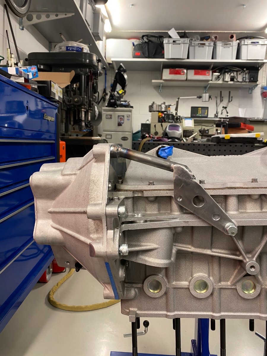
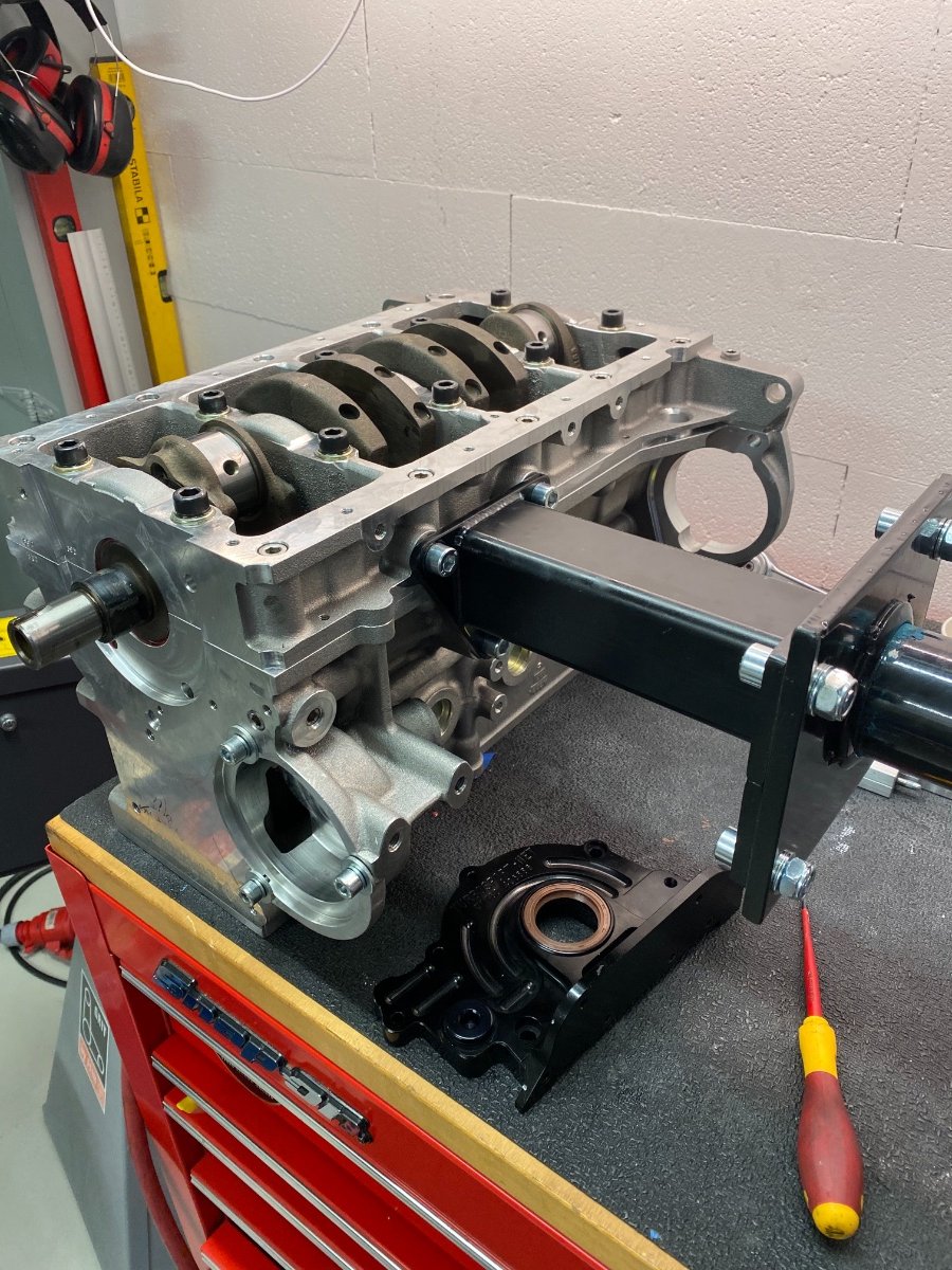
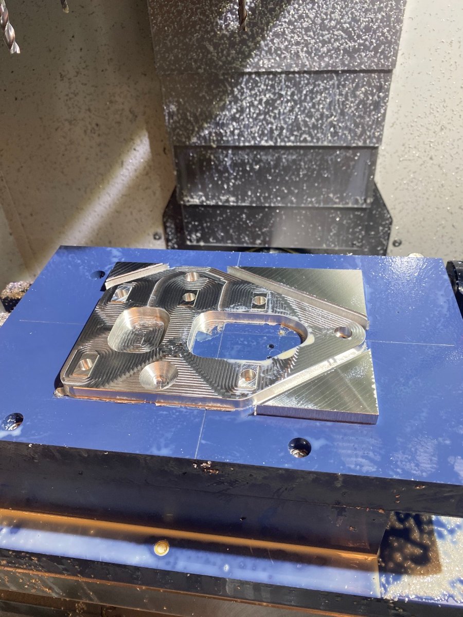
The I finalized the bellhousing bracket and behold, this was the first thing that I have so far hit with the car from underneath - it was worth the trouble! Some laser etching bling as well to bright up the day. A Cometic metal 0.051" gasket was used for the head, the piston edge protrusion was 0.25 mm and my squish clearance was 1.04 mm, while SBD recommends 0.85 mm. They have considered that the block is planed as well, but with my sparkling new block there was no need. This lowers the compression ratio a little, which ended up by measuring the head volume and using the given piston volumes, gasket thicknesses and my squish clearance in a 1:11.9 compression.
-
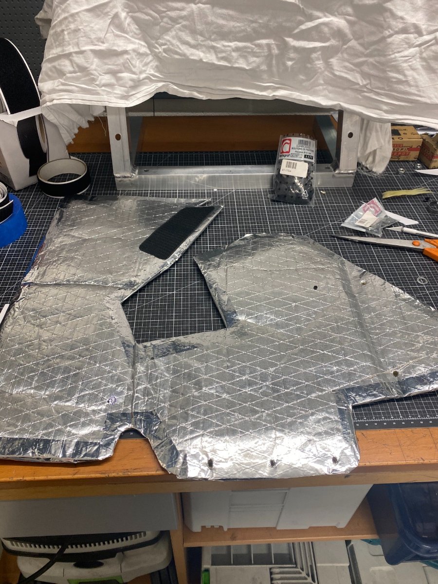
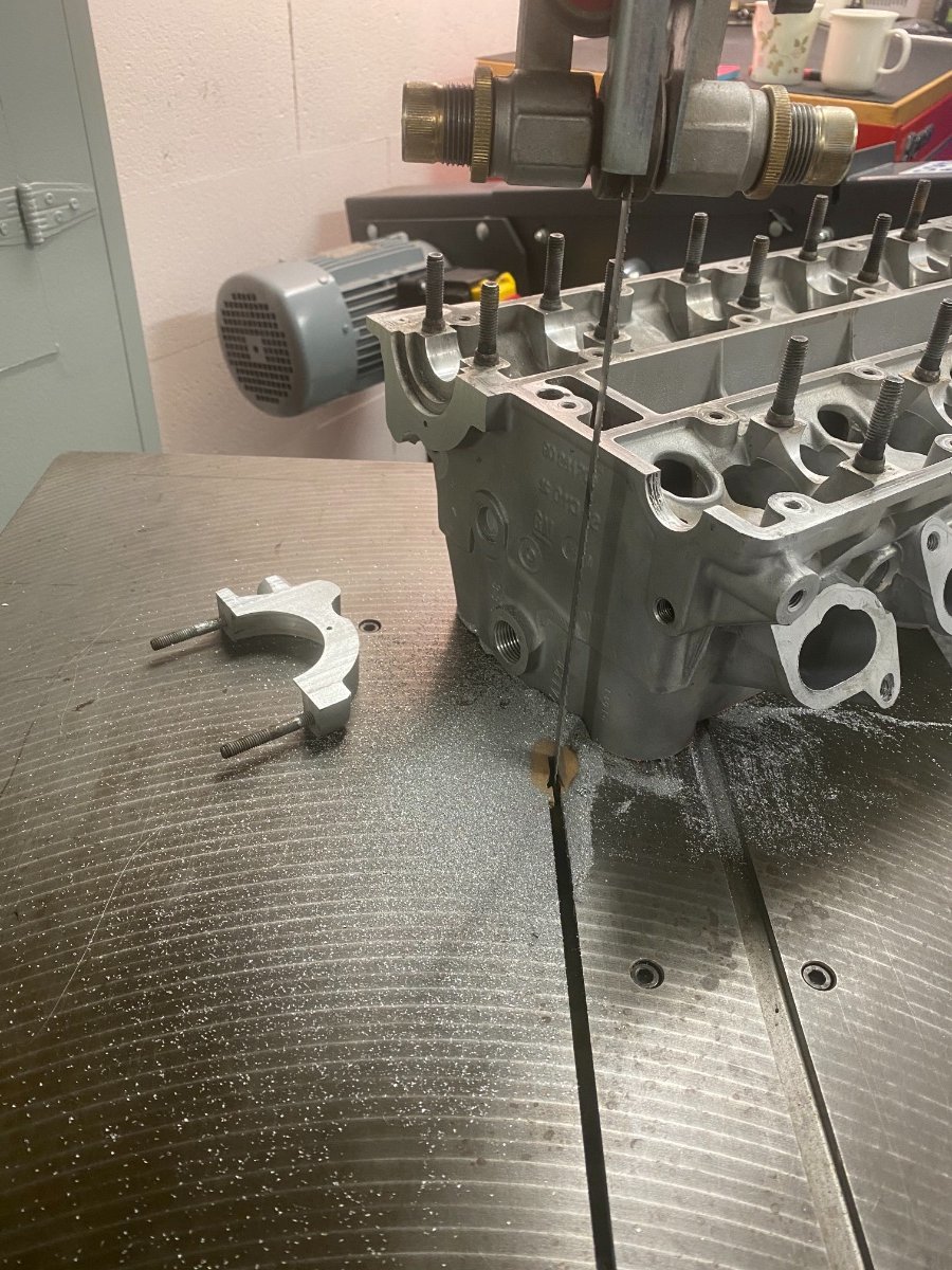
I had ordered a swirl oil / air separator cap for my drysump tank from the UK, but they apparently forgot me, so I made one. I couldn't find any details how these actually look inside, so this is just my best guess and of course I again forgot to take picture of the internals... I digged into my scratch bin and off we went. I didn't remember I had used a thicker top plate on the tank to facilitate welding, so I was carefull not to burn thru the thin sheet (1.5 mm) I thought the tank was, and ended up with a slightly cold weld. I've unfortunately lately found one pinhole in that weld. So far after 1000 km I don't have any oil in the catch can, so the top part at least seems to work well. With a 70-80 degC oil tank surrounding your feet it will be cozy warm, so I put some Thermatec insulation around the footwell to prevent as much heat transfer as possible. The valves/springs/bottom plates/spring retainers find their place. Then a major headache, the lash caps. How to grind them into spec, as I need to create a fixed clearance of 0.020 - 0.025? I come up with and idea to use my Tormek tool sharpener. I use its drill sharpening holder and use a steel rod with a 7 mm protrusion (valve stem size), on which the cap can rotate when I press it agains the grinding wheel. The rotation is created by the fact, that I'm never perfectly straight to the stone. The process of grinding the lash caps takes 2 full days and everytime I measure I need to put the cams back on. Those springs are stiff, so I made myself a press tool from 2 C-clamps to reach the threads of the cam caps. And when rotating the cams, you need to do it in sync, or your valves hit each other... (trust me on this). And one important detail - once the grinding is done, the lash caps need to be hardened with heat treating. Red hot and then drop into water. I found out about this almost accidentally and it would have been a catastrophe waiting... I guess every engine builder knows this, but at least I didn't.
-
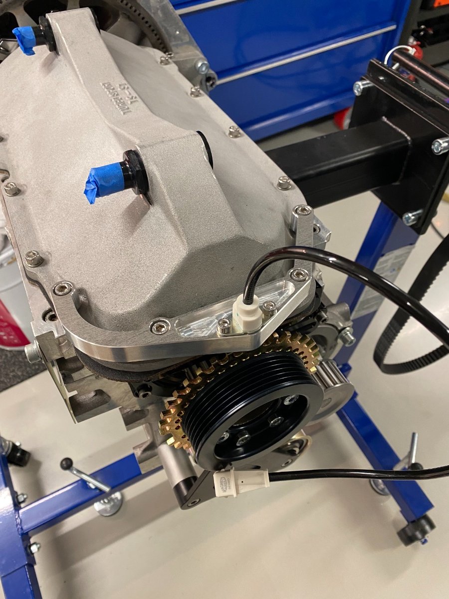
The pulleys for the drysump belt lined up perfectly! Next was to figure out how to mount the crank trigger. I used a VR sensor from Magneti Marelli 352316170849, I chose a bottom location as there were belts all around. I also made a stand for the cylinder head out of scratch aluminium (from my first version of the Tillett seat rails, yes, I make everything look here much easier than it was in reality... ). When I trial fit the bellhousing it hangs below the sump. This will catch everything under the car, so I'll need to figure out some protection for it. I also make a plug for the no longer needed distributor hole.
-
Engine build time! My main bearings are ACL Duraglide 5M2327-25, so 0.25 mm oversize. And they don't fit. We didn't realize, that also the thrust flanges are oversize, i.e. the width of the thrust bearing shell is also 0.25 mm larger. The crank needs to go back to the machine shop. My bigend bearings are King CR4017XP0.25 pMax Black. The Saenz ROD-VX-2.0E-149-01S come with ARP bolts and the instructions recommend to torque by elongation and not by torque, so I make myself a simple stretch gauge from a scratch piece of aluminium, which I can use during assembly. The structure of the Millington block is different to the C20XE block and it has a large bearing cradle, my clearances check out ok, they are 0.04 mm for the mains and 0.055 mm for the bigend. The thrust clearance is 0.08 mm. The piston ring gaps check out ok, no grindinding needed there. I forgot to by a conical piston installation tool, so I made ghetto piston ring comressor, luckily I didn't brake any rings... I maintained a record of both the torque and stretch and interestingly enough, a few bolts needed much more torque to stretch the same amount as the others. It was one of those moments, where you are not completely sure if this is right or not, but I went with the stretch.
-
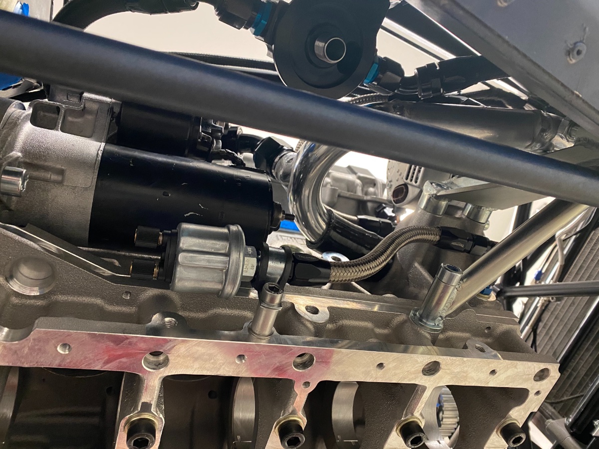
All oil lines are either AN10 or AN12. 2 lines from sump to pump. One AN12 from pump to oil tank. One AN12 from oil tank back to pump. AN10 from pump to thermostat. 2 x AN10 from thermostat to oil cooler. AN10 from thermostat to filter. AN10 from filter to engine block. It is hard to capture the line routing in images (especially since they all black...) I don't like long water hoses, so I made some 34 mm aluminium tubing for all long lines, it was also then easy to connect the water tanks, by passes etc to the aluminium tube. You can also spot my oil pressure sensor versions 2 and 3 in the images... The chassis loom is ready and the engine loom starts to take shape, but to finalize it I need the engine in its final configuration.
-
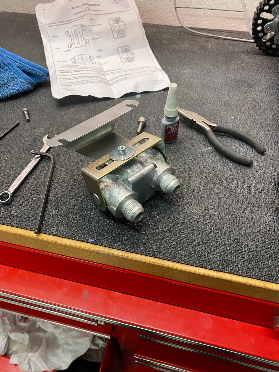
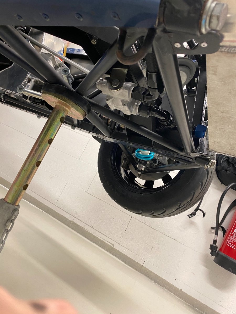
The coolant tank is the classic Volkswagen tank, it just needed a mount. The steering column needed a new cover as well. I found a nice oil thermostat from Mocal and I picked a location for it below the steering rack. I was running out of ideas where to place my oil filter, until I discovered a V shaped mount in the chassis below the intake manifold. I still don't have an idea what it was intended for, but with some modifications to my part it fit perfectly and the location is great from both a hose management and oil filter exchange. I had also enough room to fit the larger Ford filter.
-
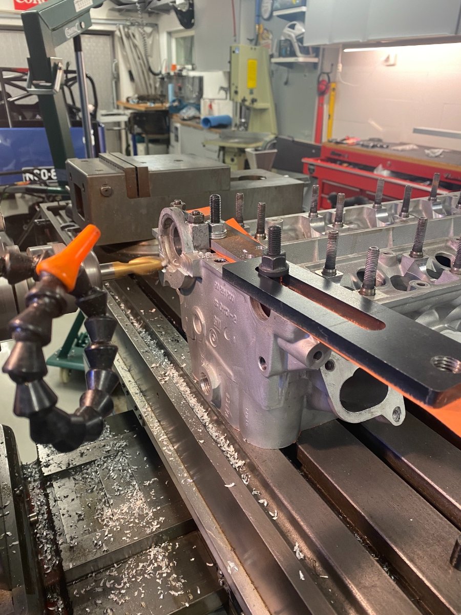
I'll be running everything sequential, so I need a cam sensor. The Millington cam cover had a place for it, but of course the sensor I selected (blindly that is) didn't fit. So I had to modify the cover a little. And who could resist some bling... Lotus Racing sign to the radiator made with a laser. The hose angles on the radiator made no sense to me, so they needed some rework as well. Next was the drysump tank. Absolutely no space to fit anything off the shelf. The only space I had was in front of the driver footwell, but that is also where my steering column now was. And the exhaust. And the drysump pump. Of course I forgot to take a picture of the baffles inside the tank, but they exist... The cylinder head visited a machine shop to fit the larger (intake +2 mm , exhaust +1 mm) valves and my wallet was again also quite a bit lighter (the theme is all about weight savings...)
-
I make my brake lines from AN4 aluminium hardline and route the rear brake similar to the fuel lines. The front ends behind the radiator, from where I continue with braided hose. I also buy from Ebay a first generation C20XE crank, which is very light with 12.7 kg. But in bad condition, so it needs a full regrind. I remove the timing /trigger wheel, as I'll be using an external trigger wheel because of weight and durability. The rear brake hoses touch the wheels, so I had to rethink quickly bracket to keep them out of trouble. Its all in the details... and I've never seen these things on a Caterham assembled, so it is what it is... The ECU is now connected to chassis loom and talking with the AIM display, so all set for the engine loom. I also make pieces from scratch to plug the holes I had to make when fitting the engine (as it was more rearward than the original).
-
So the gear stick needs some attention, out comes the hacksaw again. The alternator clears the chassis tube - barely... The head receives a coolant bypass AN8 fitting. This is found in the original C20XE intake manifold, but usually not found in throttle bodies. Race engines don't usually use it at all, but it warms up the engine faster and just makes engineering sense to maintain a proper flow also when the thermostat is closed. As my engine is more rearward, I now don't match the mounting holes in the chassis... so I modify the old mount to have 4 mm offset. I used 2" Sabelt endurance harnesses, which have the lapbelt as a pullup, but had to modify the bottom mounts to fit chassis points.
-
The engine gearbox contacted the footwells on both sides... I reused the original caterham mount on the intake side, but added one support tube and an alternator mount. The alternator is usually on the other side, but this is where my pump is now. The alternator is the small Nippon Denso unit, this one is most likely from a Kubota. The new drysump mount looks good. I also make an adapter to fit a VDO oil pressure sender - Later on I end up with 3 versions of the oil pressure sensor setup before the final one due to space restraints... And I cut the footwells for clearance. The bonnet clears the engine - great! But my new Quaife gearstick is far too long...
-
I also made hardlines from the tank. The drysump pump was much too low, so had to design a new mounting point and attachment plates. Saenz conrods and Omega slipper pistons arrived (only one compression ring), made a longer drive pulley for the drysump pump and started to make the engine mounts. I tried to match the HPC location for the C20XE engine, but ended up with an engine/transmission 4 mm more backwards. This doesn't sound much, but caused quite a bit of trouble...
-
Hi John, that is a good idea to tilt the MXS. The motogadget has been fantastic, I love its keyless start function (mobile phone) and the fact that I can use the app to switch on everything separately to test them. The MXS actually has one output, and I'm using its built in light sensor to serve as an automatic switch between DRL and low beam - the MXS output controls one relay, that just switches the low beam output from Motogadget to DRL in daylight. Blinkstop has overlapping functions for light and indicator control, but I use it only as a relay to switch my steering wheel buttons commands to the Motogadget (to GND).
-
And Millington sends a 2.0L (86 mm bore and standard deck height) engine block and cam cover - the weight is now bearable, this time around 20 kg. My "kit" came with a few old Bosch starter motors, so I picked the smallest one and reconditioned it. The camshafts had the distributor attachment, so I cut it off and plugged the oil passage. I was able to borrow some flaring tools over Christmas, so I switched to make some hard fuel lines. I was on a roll with the pipes, so I also made the filling venting system out of hardline and added a venting line with a checkvalve, which closes if I flip the car over.
-
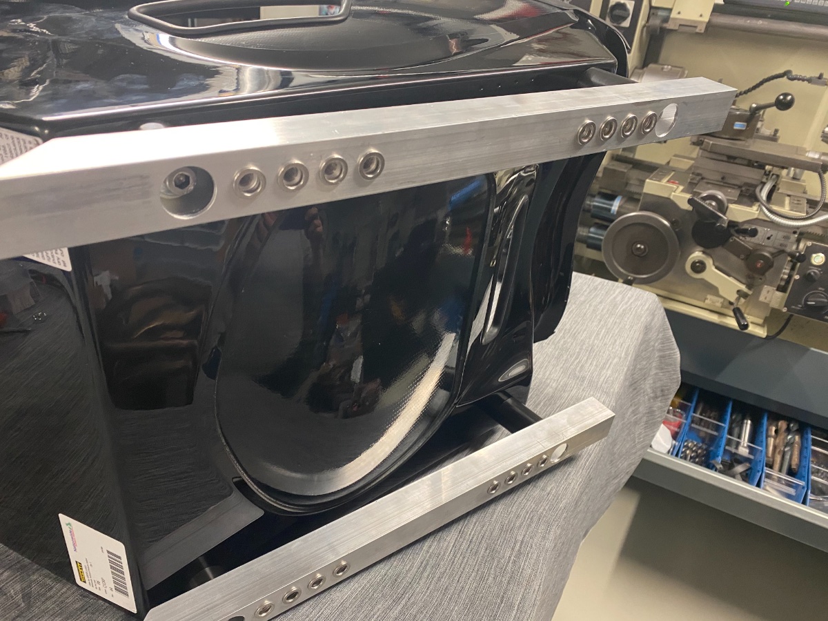
Next some 30 x 30 mm aluminium rails for the Tillett seat with multiple fixed position options. The seat is slightly tilted backwards for more head clearance. The coil on plugs came from Honda Type-R (Denso DIC-0105). The 22XE crank weighted more than 18 kg and the iron block more than 40 kg... too much! The Ford diff has no handbrake cable mounts as the newer ones, so had to creative and made a bracket into the propshaft tunnel. I then routed the cables around the driveshafts. Turbosport.net sent a nice package: Drysump system, flywheel, dual clutch, larger valves, dual valve springs, race spec camshafts, cam pulleys and solid lifters
-
Work continue on the head and I used an old 22XE block to dryfit the engine. I had some old Caterham HPC engine mounts (in horrible condition) and I was really worried about the drysump pump, as the original HPC had a fancy pump with a long driveshaft clearing the waterpump on the intake side. My only option was the exhaust side, which had the engine mount, alternator and steering column at that exact location...
-
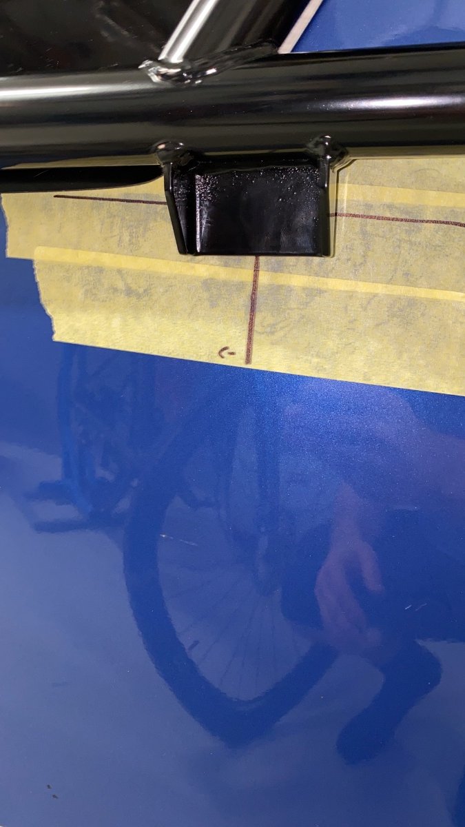
My rear fenders were carbon, but not in very good shape. Also the mounting holes were pretty randomly spaced... but when I looked at the price of new ones, I decided to fix them by laminating some more material to the flange, I also used a drilling template out of plywood to help place them symmetrically. This was also becoming exciting, as I found locally a C20XE head that had been CNC ported, but no other work done to it - so Opel/Vauxhall C20XE engine it shall be! The head was soda blasted to clean it out and all oil plugs had to be drilled out, as they were simply too tight. I was going for coil on plug ignition, so distributor parts had to go... Made a break light and used Sikaflex sealant to fit it to the roll cage tube shape, then mounted it with double sided tape. Also made an engine stand adapter for the C20XE block.
-
New Tilletts B6 arrived. They barely fit into the car, I barely fit into the Tilletts... The tank honeycombs needed some trimming and it was a big relief to find the roll cage attachments in the frame. Digging them out and drilling the cage was quite interesting, I also didn't use washes for spacing but made some spacers out of alu.
-
To make filling up easier I made a special nipple to connect a breather pipe to the filler neck rubber, also finalized the tank fuel system with a filter. For the ecu, fuel pump and electric fan supply I used automatic fuse switches from Blue Sea, together with the Motogadget M-unit there were no other fuses needed. Chassis wiring was straighforward, I used Mil-Spec aircraft wire and didn't use the chassis for ground at all - I rather have one ground point which is pulled to every electrical unit separately. I also had some old Lotus logo 3D stickers made for the shifter and hubcaps. The shift knob is also custom made.
-
The wheels needed center caps, so made them including the retaining springs. IMG_2173.MOV
-
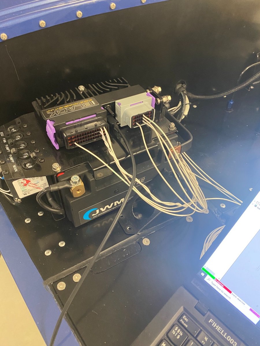
I decided to put all electrics inside the scuttle, but accessible, so started with a simple tray layout. Also used a laser to make some rubber seals for the tank. The battery is a Lifepo and decided to use it also to mount the ECU.
-
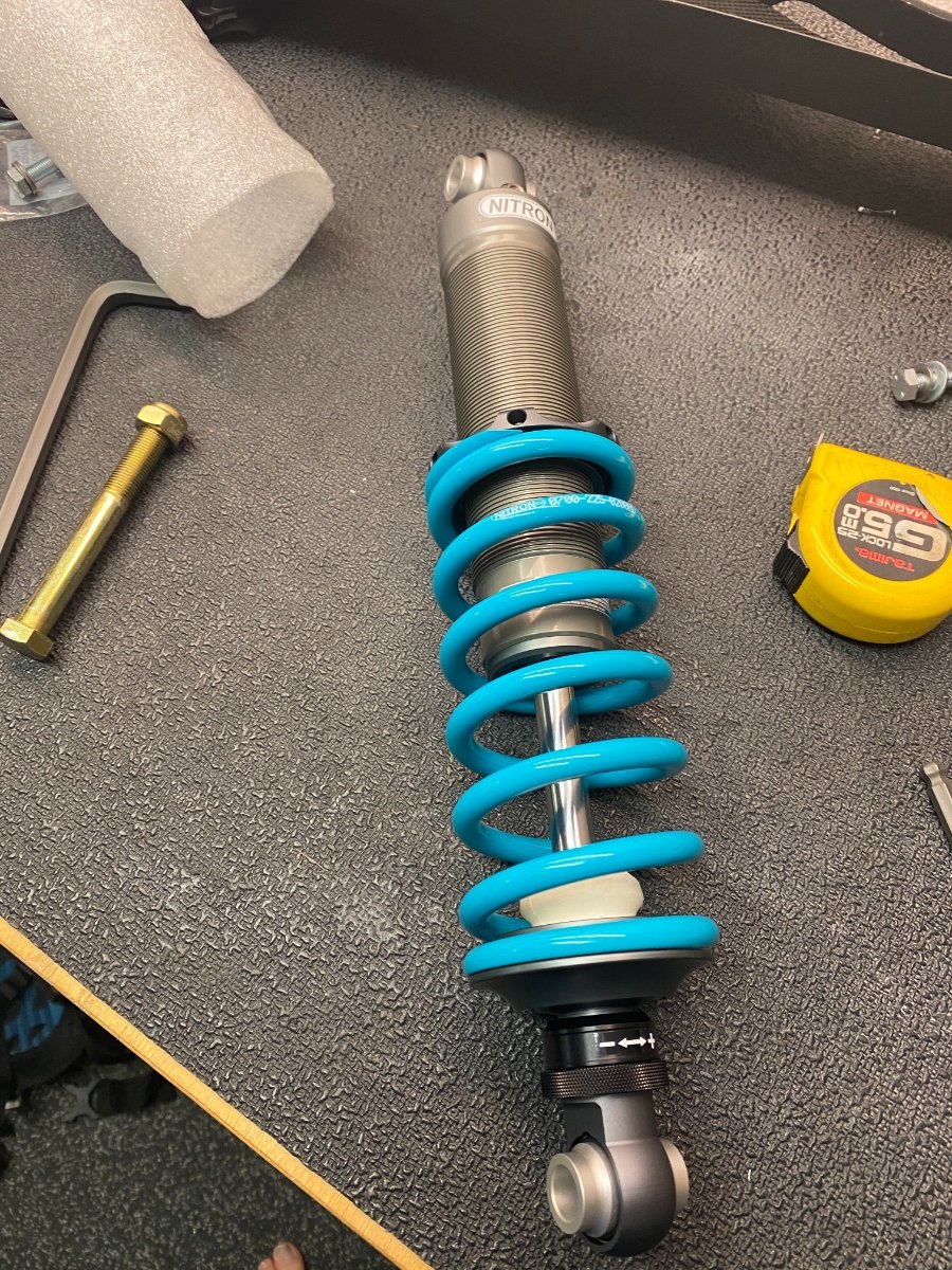
Ordered new swivel linkages for the rear sway bar, the original Caterham ones didn't feel that great. Got some LED light inserts (Highsider, Germany) for my 5 3/4 carbon buckers that came with the car (yes!), used Kellermann motorcycle LED indicators for the front with some custom brackets - they turned out really nice. The AIM display was a nice piece of kit, however when the sun comes from the back I must say it is impossible to read - I would now go for something else. For the battery isolator I went with Cartek, so I could have a cutout on both sides of the car. Simon from Meteor provided new Nitron dampers with his custom valving.
-
Then had the RHD to LHD conversion inspected by local authorities, it was easy to lift onto a small trailer with and engine hoist and my shop lift - all was ok, we were good to continue. Next was the fuel tank conversion to fuel injection. I built an in-tank swirl pot with a transfer pump that would fill the pot (VDO) and high pressure pump in the pot.
-
The electrical system was selected and orders started coming in: Motogadget M-unit blue with RF ID key Ecumaster black ECU AIM MXS 1.2 Strada display over can-bus to Ecumaster Wireless buttons for steering wheel from Blinkstop The car came with an old radiator, which seemed to be from a R420 (non-race). For some reason the radiator was separated from the oil cooler, which I later learned was because it was leaking... but at this stage I proudly welded them back together and fitted. The cowl was made to fit with some separate bottom brackets and by cutting of wide strip of material. I also purchased a large fan to mount in front of the coolers. The front number plate hangs low and I don't like when they bend, so some carbon fibre was laminated behind it to make it stronger. Also found a rubber 90 degree fuel filler hose. Caterham supplied the rear brakes, the car came with James Whiting Alcon 4 pot brakes (nice!).