Rosteri
-
Posts
179 -
Joined
-
Last visited
Content Type
Profiles
Forums
Store
Articles
Gallery
Events
Library
Everything posted by Rosteri
-
Yeah, sounds good. I’m happy to help with one off cnc parts for a seven, if you have a hard time finding a good shop.
-
I’m using an SLA printer, so the plastic hardens chemically and not from cooling down. I’ve actually never used such parts in a vehicle before, so it will be interesting to see how it performs.
-
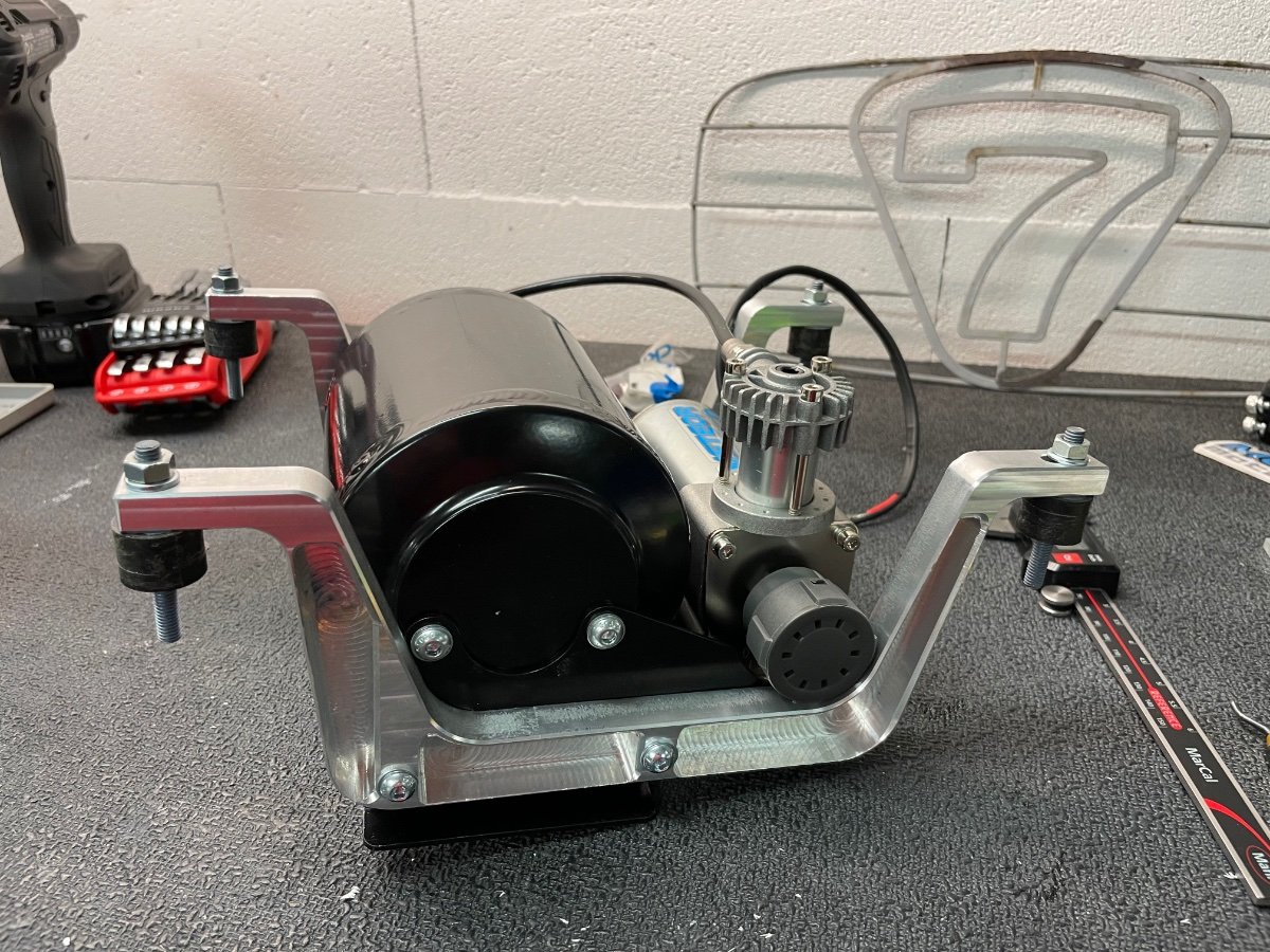
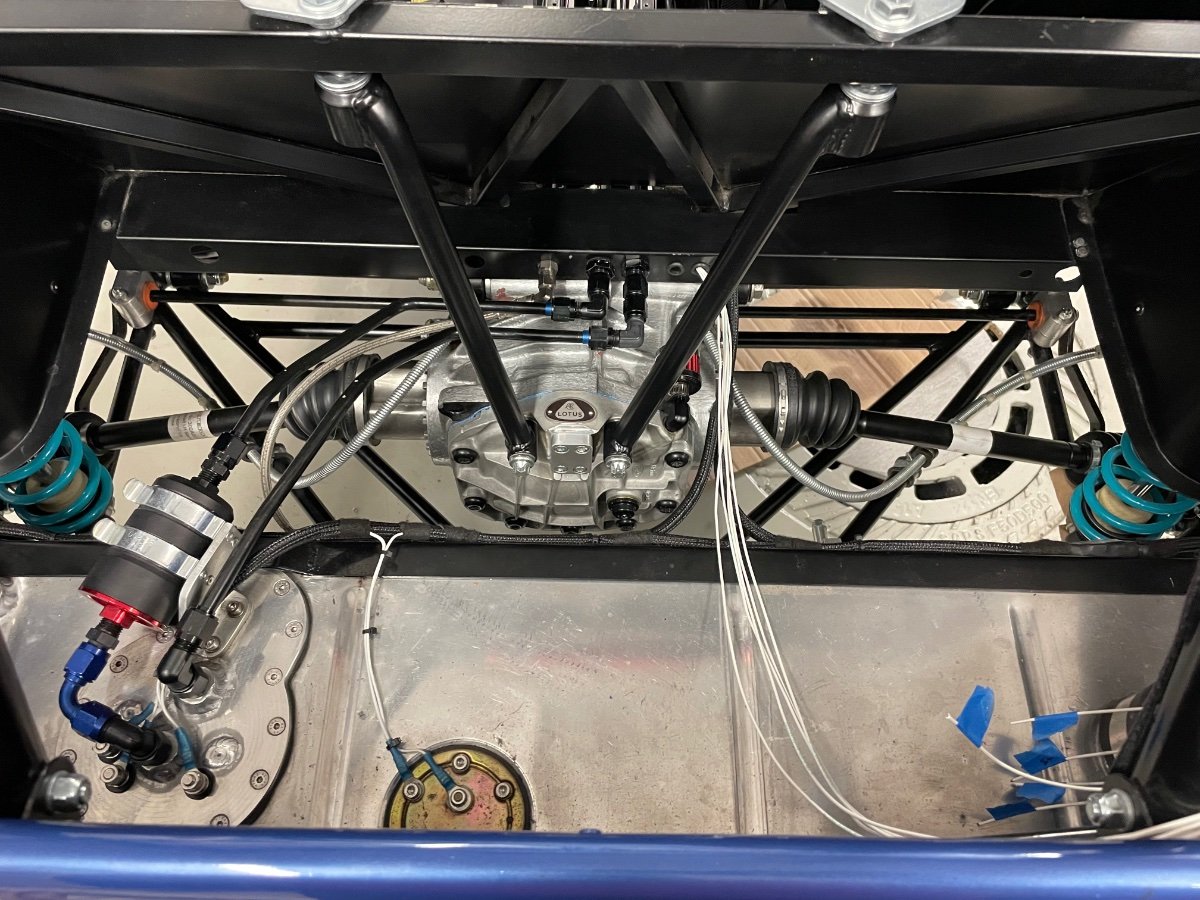
And cnc machined some brackets for the compressor. I wanted the weight rear and low, so I’m going for the space above the driveshaft in front of the fuel tank.

-
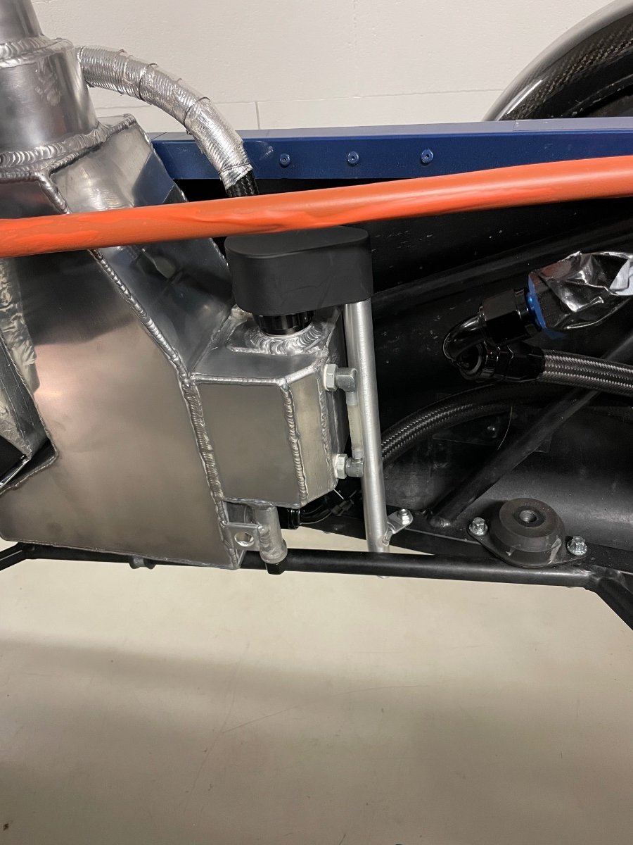
And the breather is sorted - I printed a small plastic cover, that goes over the small K&N filter and seals with a large O-ring around the base, then routes the fumes underneath the car with a short aluminium tube.
-
Yeah, your logic makes sense - and having proper AN fittings for the water tank is a big plus as well. The tank has a pressure cap setup, so my initial thought was that you need to run it full of coolant + an additional catch can with a pick-up at the bottom of the catch can, so that it sucks back any expelled coolant when the engine cools. The Caterham supplied tank works a bit differently with a large free air space above the coolant level for coolant expansion. Most European cars have this setup, I'm running a VW coolant tank. I don't like the looks either, so the Radium setup is interesting, but I don't want another catch can either. But as the Radium has a capacity of 0.7L, you might be able to run it still with an air cushion, so no coolant will come out at full temperature once you have the right level. Or just fill it up full with a purge outlet hose and then see where the level ends up once it has cooled down.
-
Radium was an interesting find - their low profile swivels seem unique and can be a lifesaver in tight spots. I also like their flex fuel sensor setup, so far I have not come across anything similar either. Also the oil catch can is nice, but Croc do think about the blow-by fumes that will exit the filter. I agree that the water tank looks fabulous, but it also appears very heavy compared to a plastic tank that does the job - out of curiosity, have you checked the weight? The pricing to me seems also reasonable, it is amazing that you can produce and still make a profit with so large CNC parts these days.
-
Nice to see an update, thanks! That air tank looks very very familiar... I'm just CNC machining some brackets for mine.
-
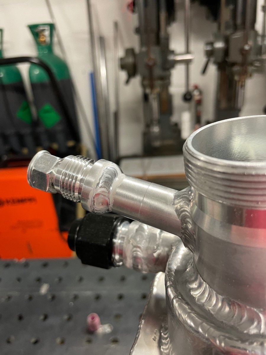
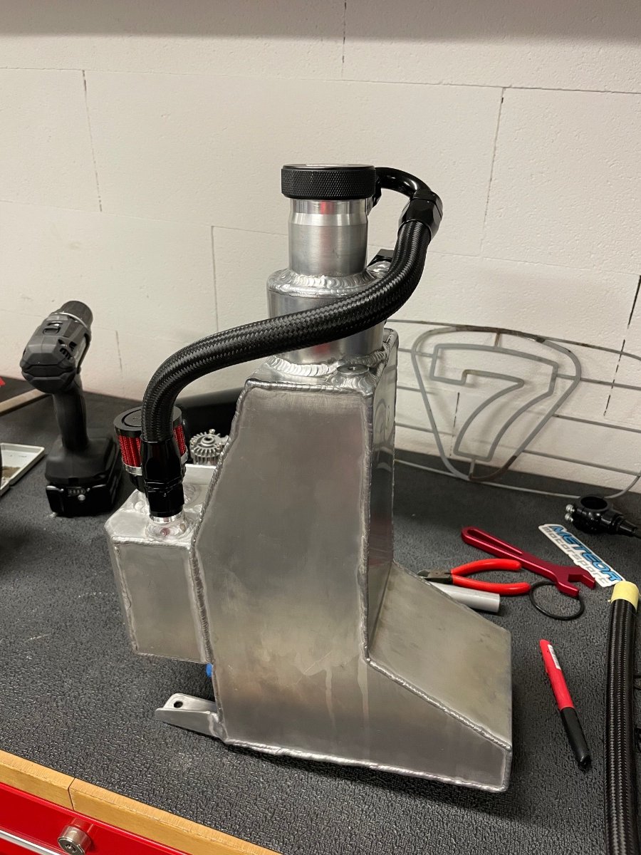
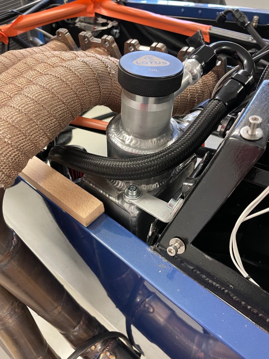
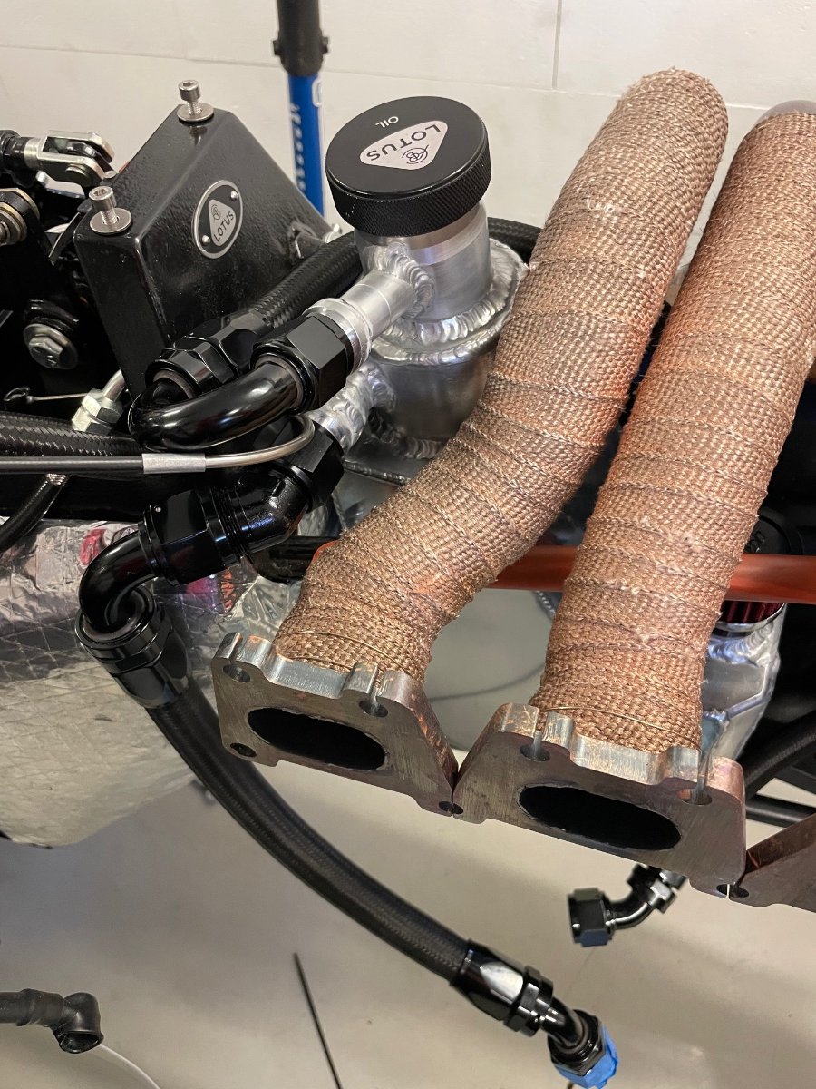
I was never quite happy with my drysump breather setup - the breather pipe to the catch tank was routed under the exhaust flange between the engine and tank and while it worked, it always hurt looking at. My second problem is the smell and fumes harrasing the driver at standstill. The breather of the catch tank is a small K&N filter on top of the tank cap and hot gases escape upwards thru the bonnet louvres. After staring at it for a week I finally have a new setup for the breather pipe/hose, but it did require some modifications to the tank. The oil system starts to be quite a labor of love… New AN10 bosses welded to the breather line: And new routing now under header. It is tight: Next is the breather fume problem. A simple solution would be to scrap the filter and just run a pipe under the car from the cap, as the oil tank most likely always has overpressure and it wouldn’t suck dust in, but this is just a guess.
-
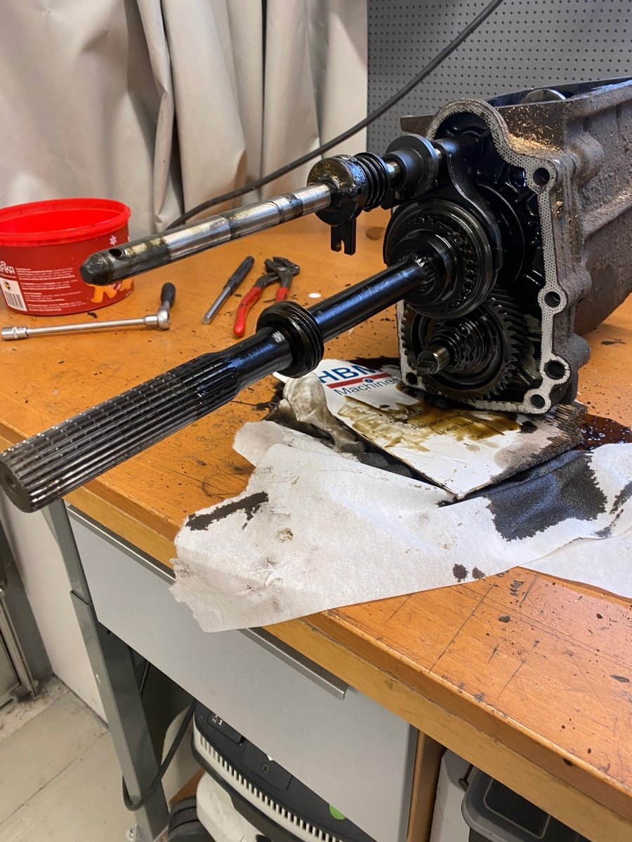
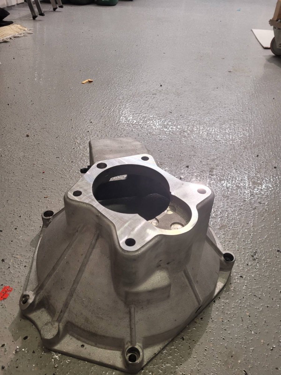
This is one of the latest T9 boxes that was in production, from a Ford P100. There is no feature on the lever shaft for a switch.
-
No idea, I always considered it a mounting boss for something.
-
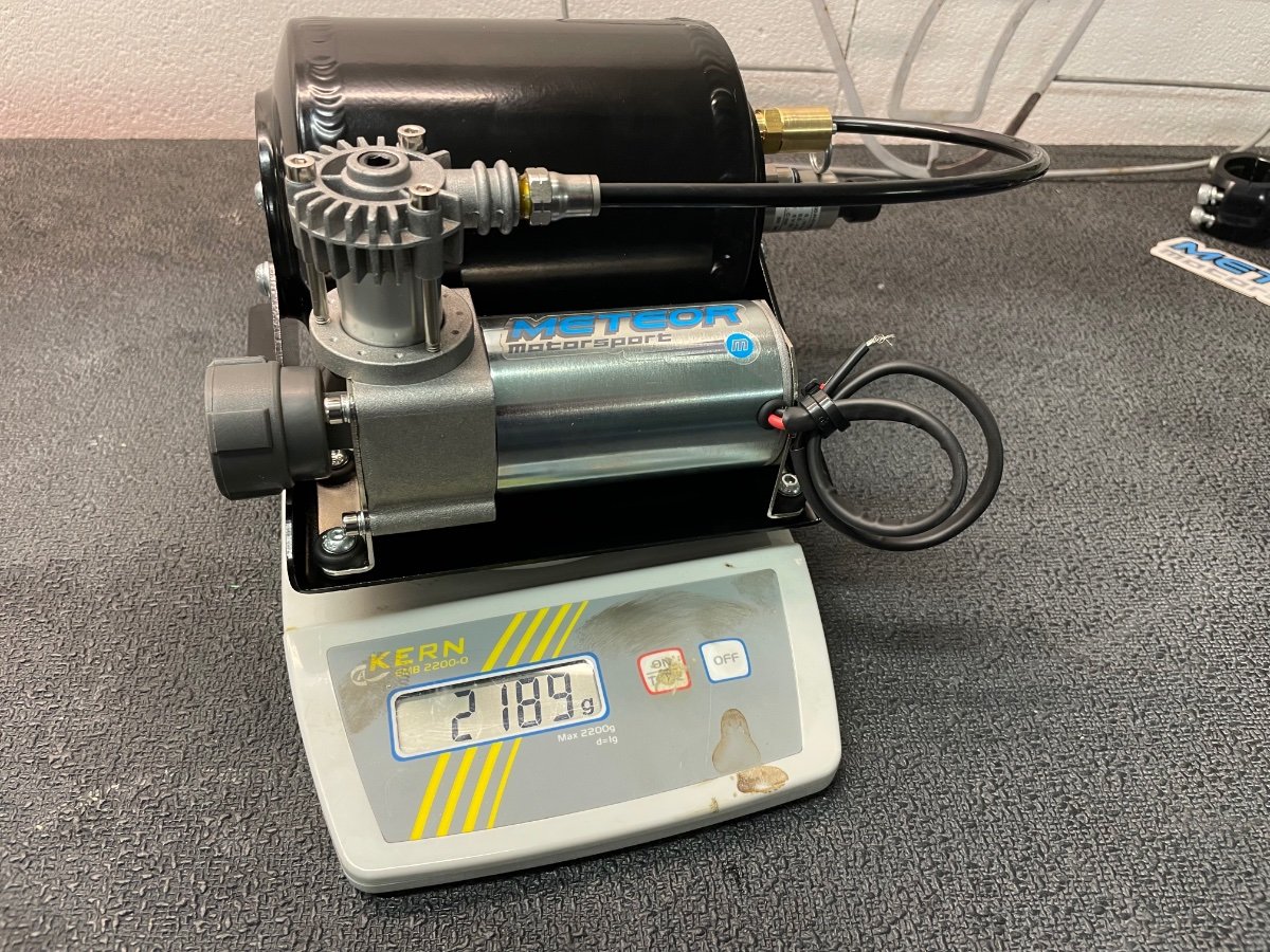
The compressor from Meteor for the paddleshift arrived: 2.2 kg, nice. Next I’ll need to figure out how to mount it into the trunk. The sound is ok as well, but I’ll support it on further rubber bobbins so it stays ok as well. For reference if anyone builds their own, the compressor seems to be a Viair 92C, that has been slightly modified. The airfilter P/N would then be 92620. So spare parts are available. The bracketry and pressure tank (both alu) look like custom made.
-
No experience on that, but it looks like it *could* fit - one would have to take the blanking plate off (a gentle tap from the inside does it). Also good to note, that all the moving parts would then be exposed to the elements.
-
Nut keeps coming loose - any long term solutions?
Rosteri replied to KnifeySpoony's topic in General Tech
I’ve noticed quite a few Grade5 (3 stripes on the head) bolts in Caterhams nut and bolt packages, which I try to replace with Grade8 (6 stripes) or AN aircraft quality when I can. My point is, that I don’t trust Caterhams bolt quality - do check and replace them. And if nothing rotates and the nuts don’t come off, bolts are ok, then I’d stop retorquing and just drive. If the chassis/strut parts yield instead of the bolt or seat themselves from the movement, then you are not doing yourself a favor by re-tightening. As a general rule in aircraft mechanics no nylocs in rotating assemblies or the engine bay (or anywhere with heat). In these cases a castle nut and a cotter pin is always used instead. This is a real pain with metric HW, as the metric castle nuts are huge for tiny cotter pins and all bolts need to be custom drilled. Also all commercial drill jigs are for imperial bolts. I didn’t follow the rule either when building mine… but it felt wrong pretty much at every nyloc nut. -
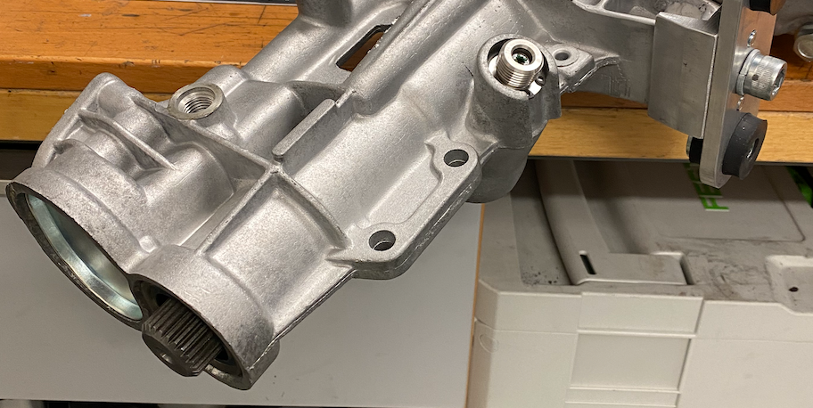
Diff struts - there is very little to be found on this subject, so here we go. Imperial S3 chassis and the right struts are the 620R race struts, which is a metric chassis. I was about to order the S3 struts, but they are for a BMW diff. There was a ~ 5 mm gap, so there is room to mount the belts also below the chassis rail for a Hans setup. My engine ended up 4 mm more rearward than originally in the HPC, so to have the Sadev a bit closer to the right position we machined the bellhousing 2 mm shorter. This is mainly to ensure the propshaft has some longitudinal tolerance.
-
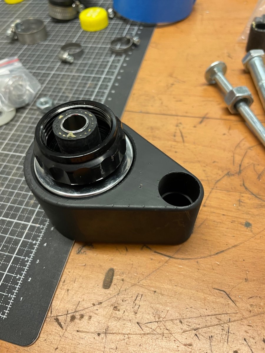
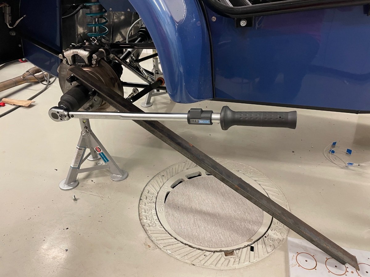
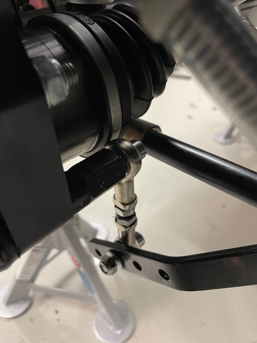
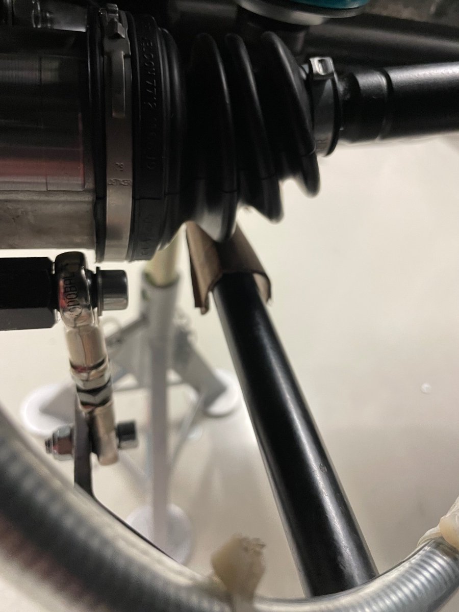
My setup to open and torque hub axle nuts with a simple L profile, that has two holes = zero drama The large nyloc nuts are a bit hard to find, so here are some part numbers: A.B.S. is an aftermarket brand and in Europe you can find them at least from part dealers like Autodoc and Aeromotors, costing only a few Euros a piece, so there is no need to re-use old ones. And the new driveshafts interfered with my swaybar link, but shortening the mounting boss eventually solved that.
-
Last year I made the diff mounting bolt spacers / shims out of plastic and this was a perfect moment to make new permanent ones out of steel with my lathe. Since I was planning to have them zinc plated, I took the opportunity also to shorten my cylinder head exhaust studs and I also refurbished a few corroded steering rack parts and the lower steering column to a like new look. They turned out really nice.
-
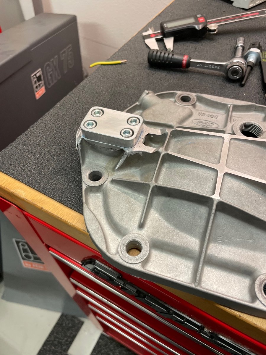
It was partially my fault, as I should have left more of the mounting boss and then the casting faults wouldn't have mattered. This rear diff is the last old part in my drivetrain and I have no idea about its history. The ZF LSD inside looks new, but for some reason the aluminium case has been painted with thick hammer paint... perhaps to make it look refurbished..? But it has been quiet, so I'll just use it for now.
-
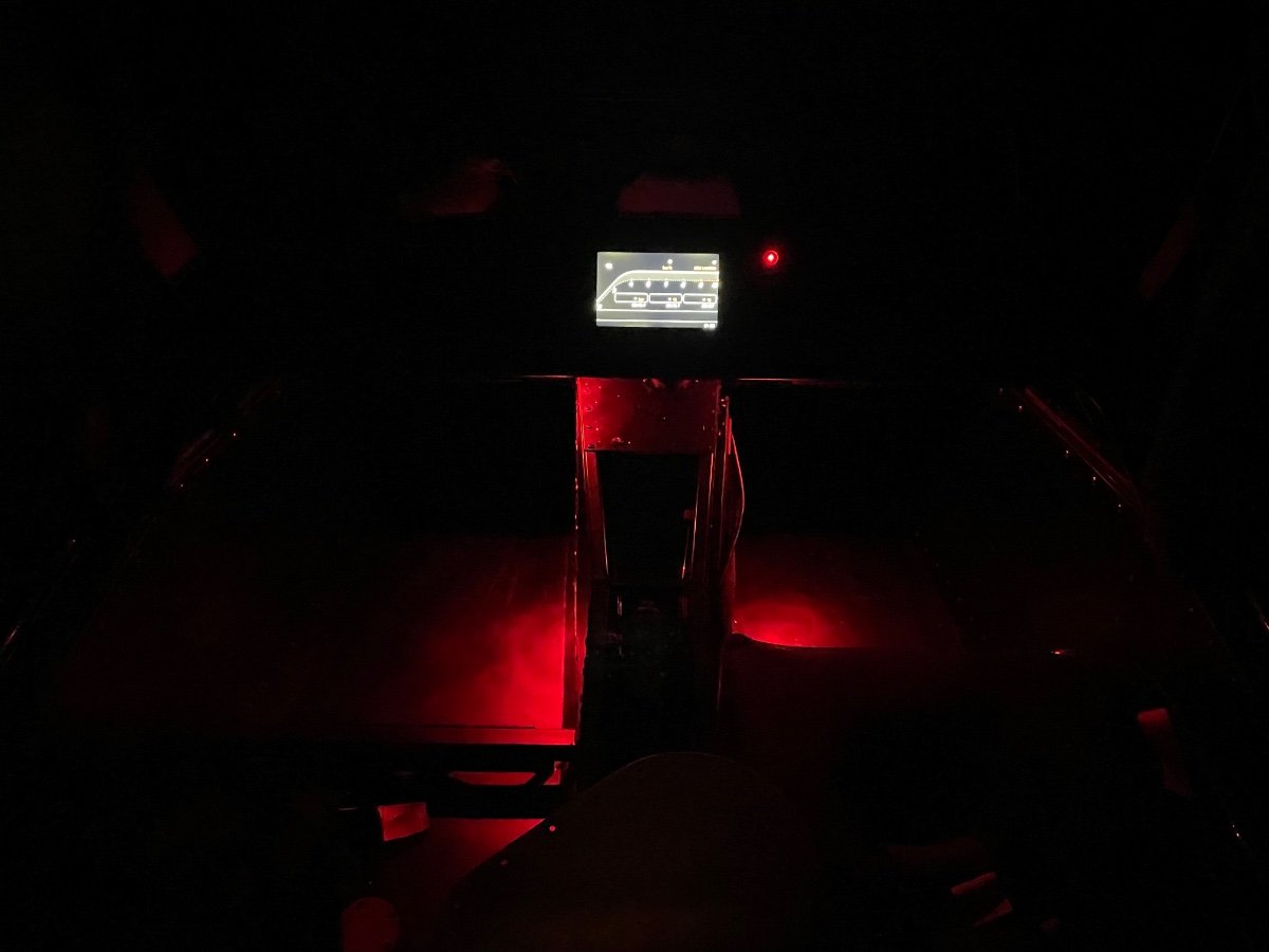
And one more to do completed - I hated driving in the dark, as my cockpit was pitchdark and it felt almost like I had no torso… two red marine indoor lights should fix that just fine. There is no driver seat on the left side in the picture.
-
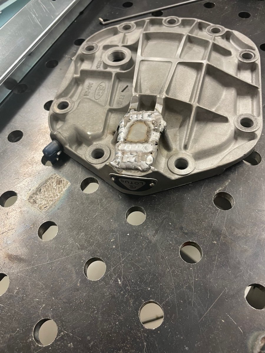
The above large Ampseal connector was horrible to work with, as one can press the contact pin too far in and then only dissassembly rescues. It took me 3 hours before all were ok… My diff backcover had a small oil weap and it was on my fix it during winter list. I tried to re-weld it - but the casted aluminium was full of cavities (and dirt) and in the end I had no idea if I fixed it or not, as crap and pinholes just kept appearing. Eventually I just machined everything off and made a cover plate to seal it. I guess this is one way to spend your weekend. I noticed Caterham parts had additional diff struts / braces also for the S3 chassis, I thought they were only available for the CSR and 620 metric chassis... I’ll call them tomorrow to check if they fit, as for £56 a piece I won’t bother to make them myself.
-
When Sikaflex reaches the end of its shelf life, it becomes very hard to press out. What is the best before date on the tube?
-
Parts continue to trickle in… Blinkstop refunded a little when I exchanged my 4-channel receiver into this new 8-channel receiver. I’ll repin the old wires from the smaller connector and then add a few new ones for the shift control on the steering wheel. It was a very nice gesture from them!
-
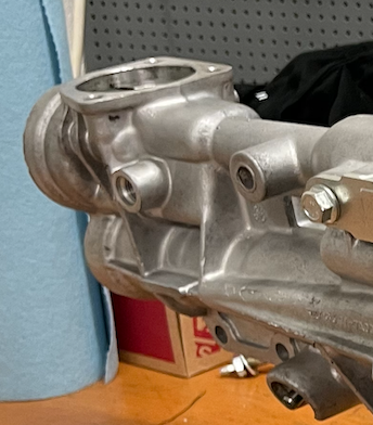
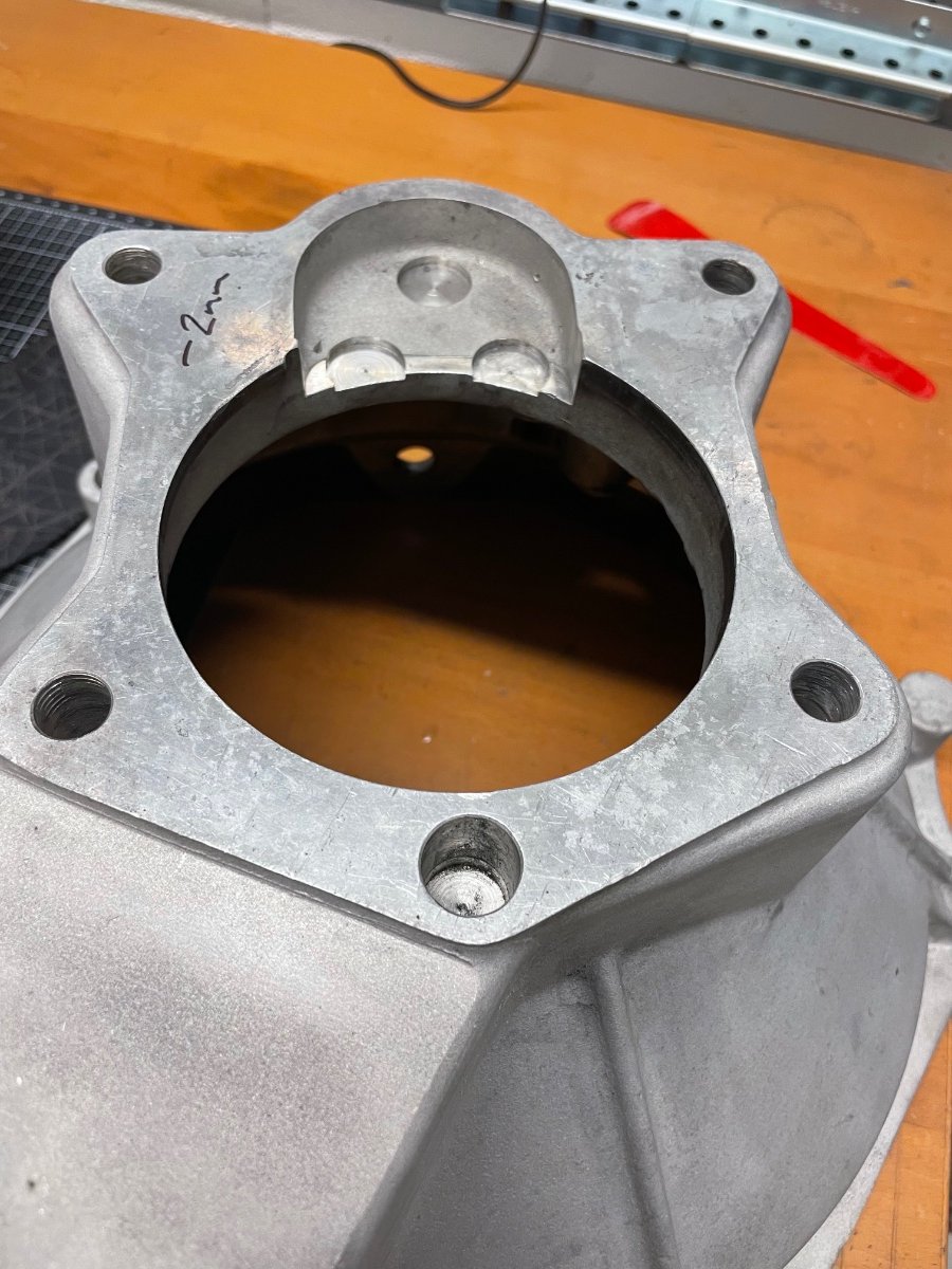
Just read the thread and still a comment on the T9 box - the needed input shaft length will depend on the engine/bellhousing combination. Some combinations take the longer one, but the center bearing tip still has to be shortened a little. If rebuilding with a new gearset, then the V6 is the more desirable starting point with its better layshaft bearing, as you can choose the input shaft length to suit from the gearset vendor. The bellhousing might need some additional machining for the layshaft protrusion, please check the picture (the area with 3 small circular holes). Any T9 box can serve as a core for a new gearset and if you want the better V6 layshaft setup on a non V6 box, then one can use a new aluminium case - it will also save further 5 kg and you get an oil drain plug. Your bellhousing looks like a cast iron one and they are very heavy compared to its aluminium counterpart.
-
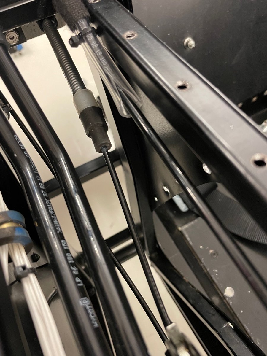
Ok, the propshaft tunnel is now (70 mm -> 82 mm) wider at the rear. I also had to remove the recess for the seatbelt on one side to have enough room to slide the propshaft in. I actually don’t need that recess with the Tillett seats, so I think I’ll make a flat replacement to avoid the hassle later.
-
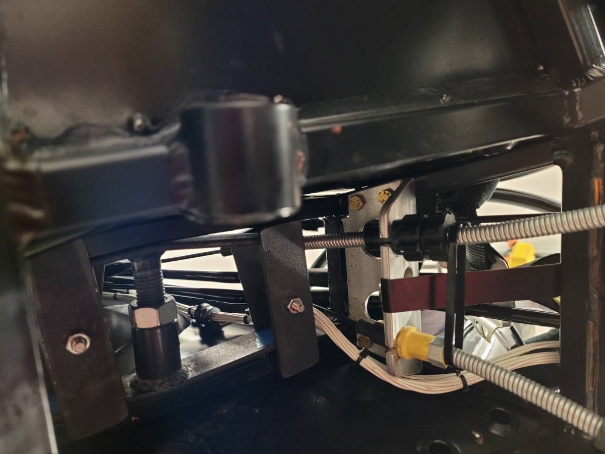
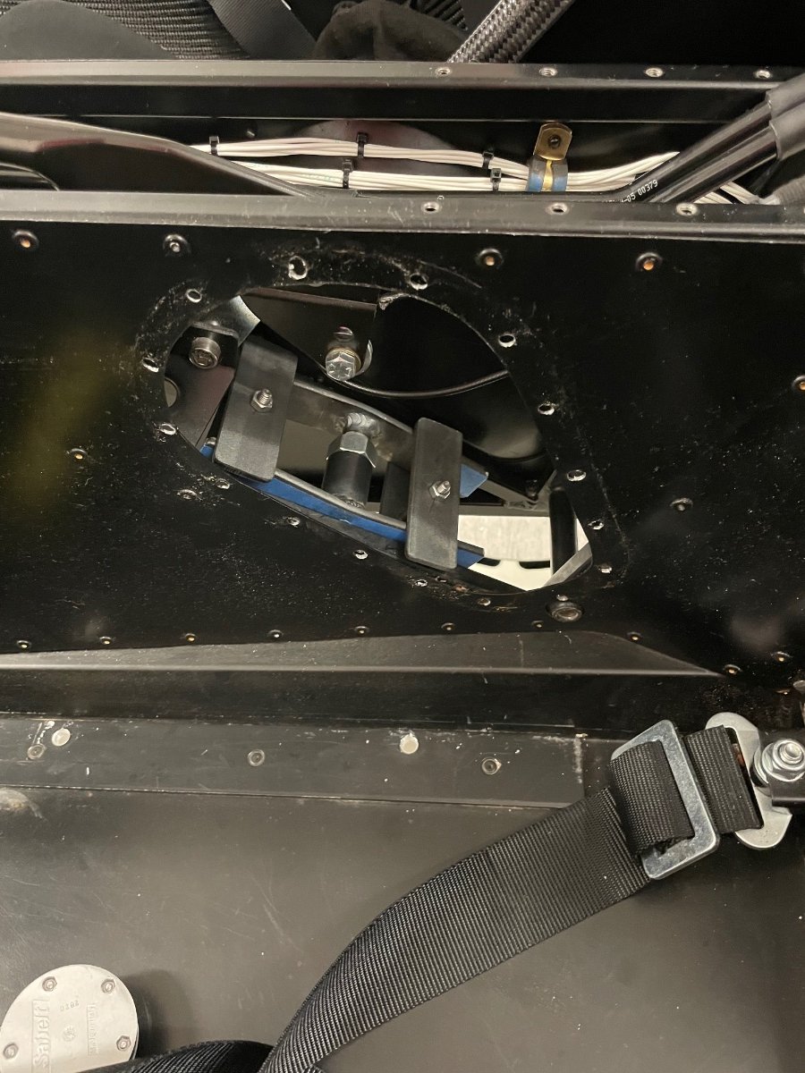
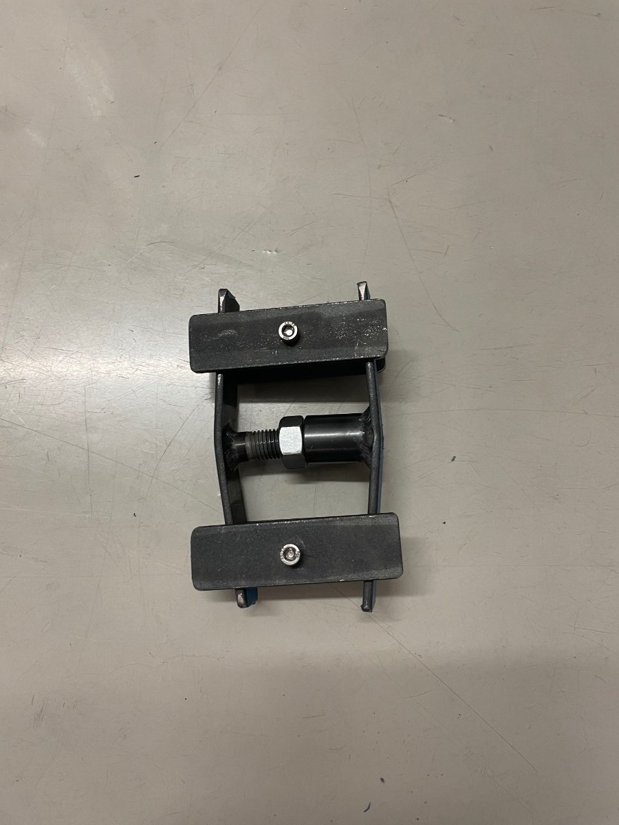
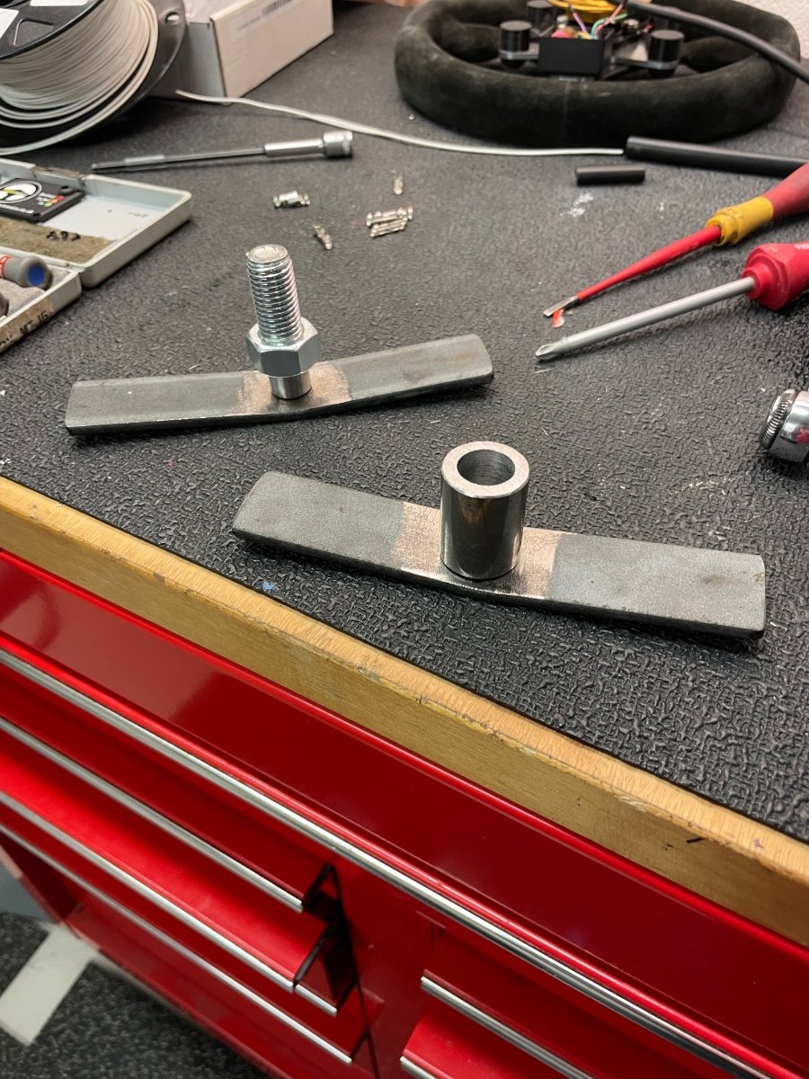
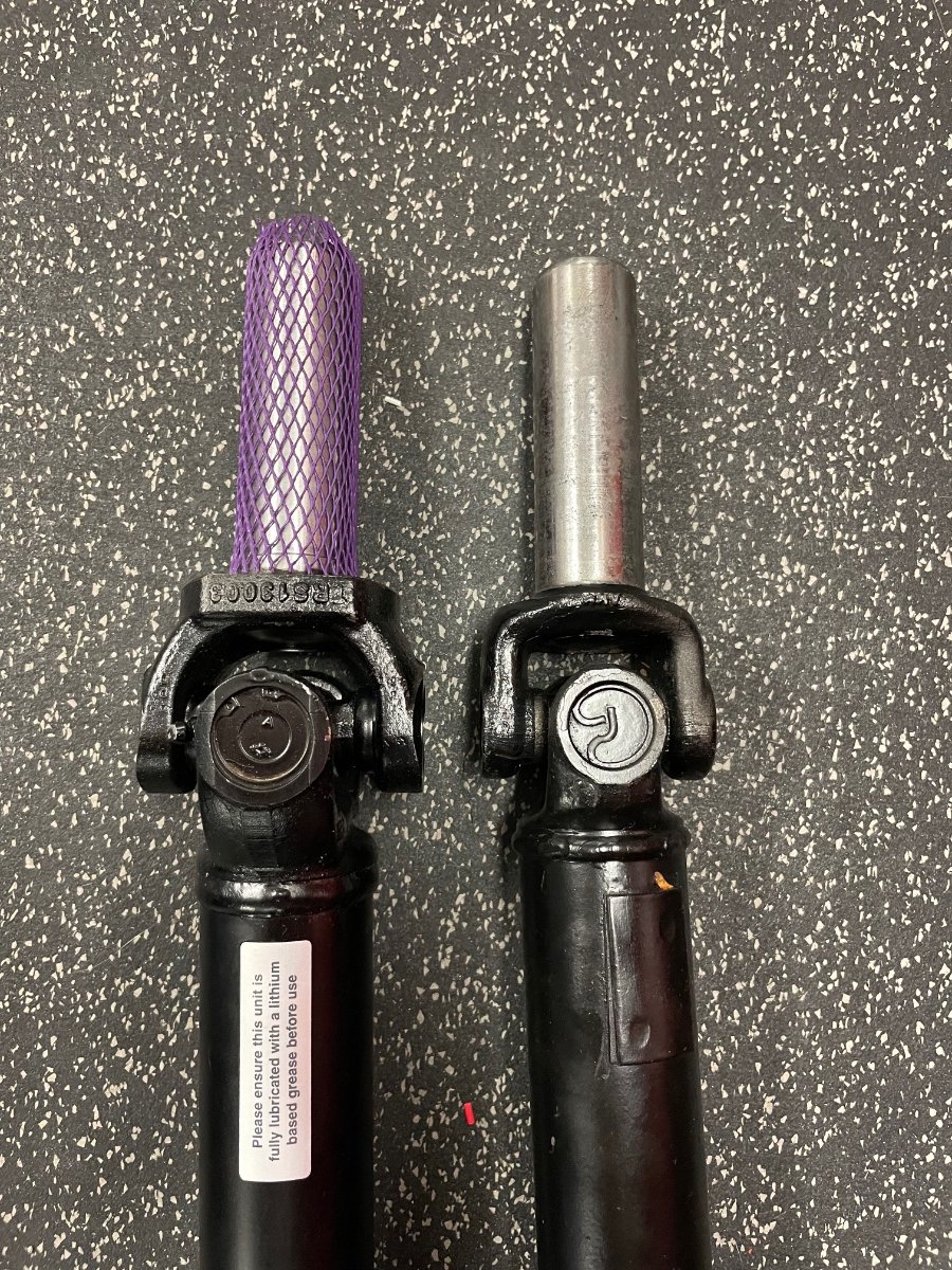
New drive- and propshafts arrived last week and today I dropped the diff to put them in. I knew the Sadev spec propshaft was larger, but didn’t expect this much… No way it will fit into the tunnel, so let’s make a spreader tool next.
-
HELP Alternator noise(?) problem, also, I ain't got no MAP sensor
Rosteri replied to sporqster's topic in General Tech
Hi, if IG and S are spliced together between the alternator and the ign switch, then turning off the engine (ignition…) might cause troubles within the regulator, as it doesn’t see the battery voltage anymore while the alternator still runs. I’d fix that. I’d also try a second alternator on the engine to rule out the alternator as a problem source, if somehow possible. Second thing that comes to mind is, that alternators do take quite a bit of power when charging (plugged), so if the problems are only at idle, then the engine might just be out of tune/ too low idle rev. Stuttering/running bad at low revs can easily create the TDC code, so it isn’t necessary the reason for the running problems, just a sign. What is the battery voltage when engine is running without/with alt plugged? Then if possible check the shielding of the trigger wires, or just make sure that none of the alternator wires are close to other wires. But somehow I doubt this is the cause.