Rosteri
-
Posts
179 -
Joined
-
Last visited
Content Type
Profiles
Forums
Store
Articles
Gallery
Events
Library
Everything posted by Rosteri
-
Thanks Ferrino! You have some good taste in car electronics =) Yes, they are just 3 alternative locations for the pedal pivot and my clutch/brake has the same adjustments. That bracket and the pedal also has now additional provisions for a position sensor, in case I’d opt for a drive by wire throttle setup -> unlikely. For the etching I’m now using a simple co2 laser. I’ve also had good success with Bungard Alucorex, which uses the pcb photoresist process with a simple uv light source and a mask.
-
Naa, just go for it. Powder coating is the worst possible corrosion protection for a frame, so that new handbrake mount will be the best spot on the frame when you are done! I don’t know how it is supposed to be, but looking at it I’d just cut it off and leave short tabs on both sides, to which I’d bolt a new piece I’d make out of flat bar or a nice machined alu part. No need to weld on the chassis.
-
Great thread, thanks for sharing. It will be such a thrill to open that box!
-
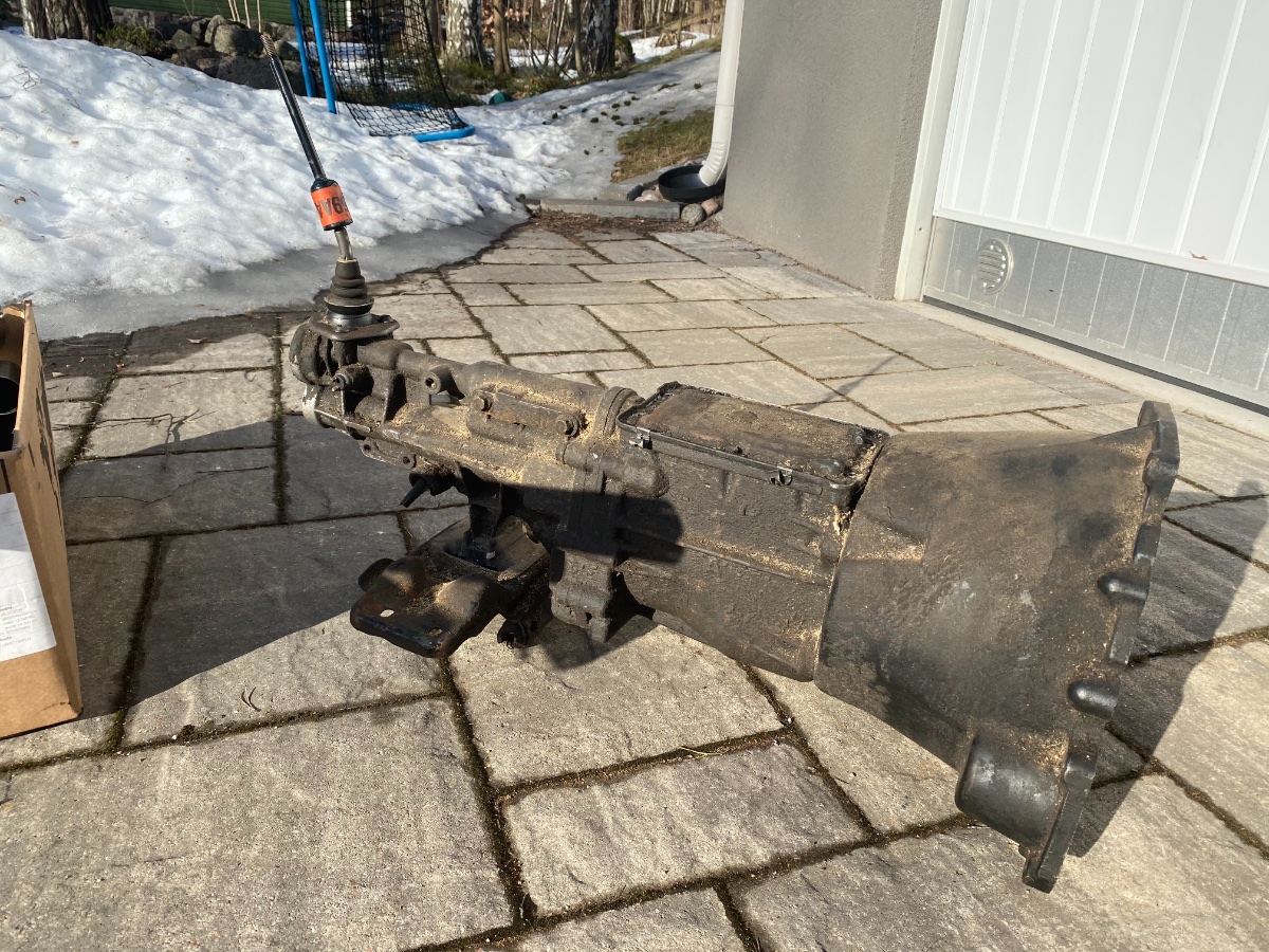
Yeah, my drysump even follows the shape of the foot well, so better to have something in-between! Tracsport helped me out and exchanged my long T9 input shaft to a shorter one, thanks Steve - super service! I assembled the gearbox today with the new shaft and it is ready to be picked up by the new owner. The drysump is now repaired and after a short polish it can go back into the car. The fitment is so tight, that it can be accessed only when the engine is out…☹️

-
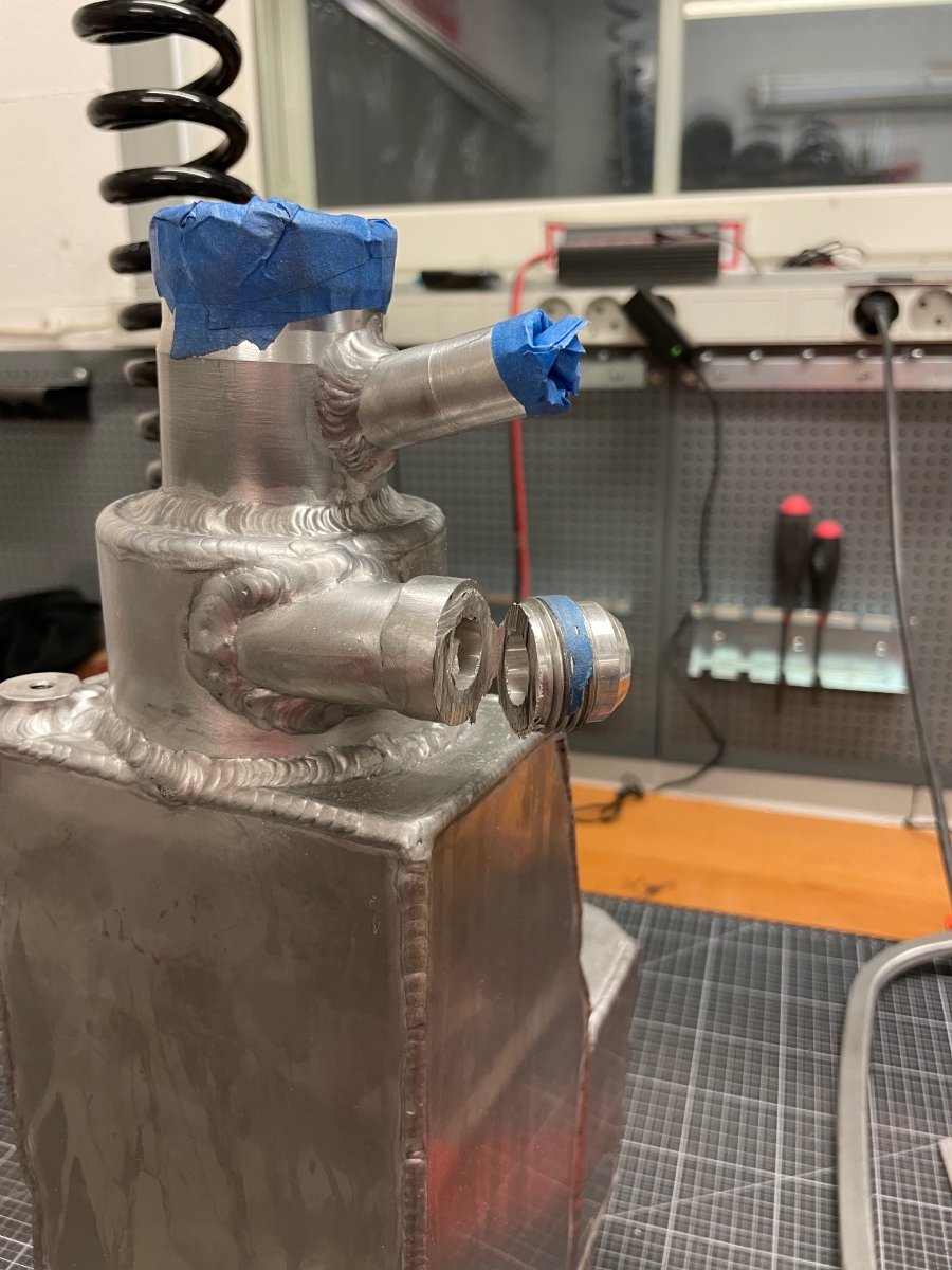
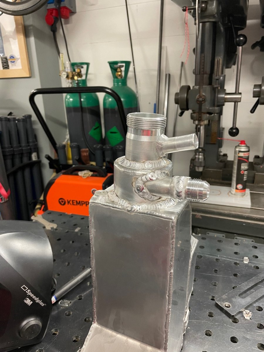
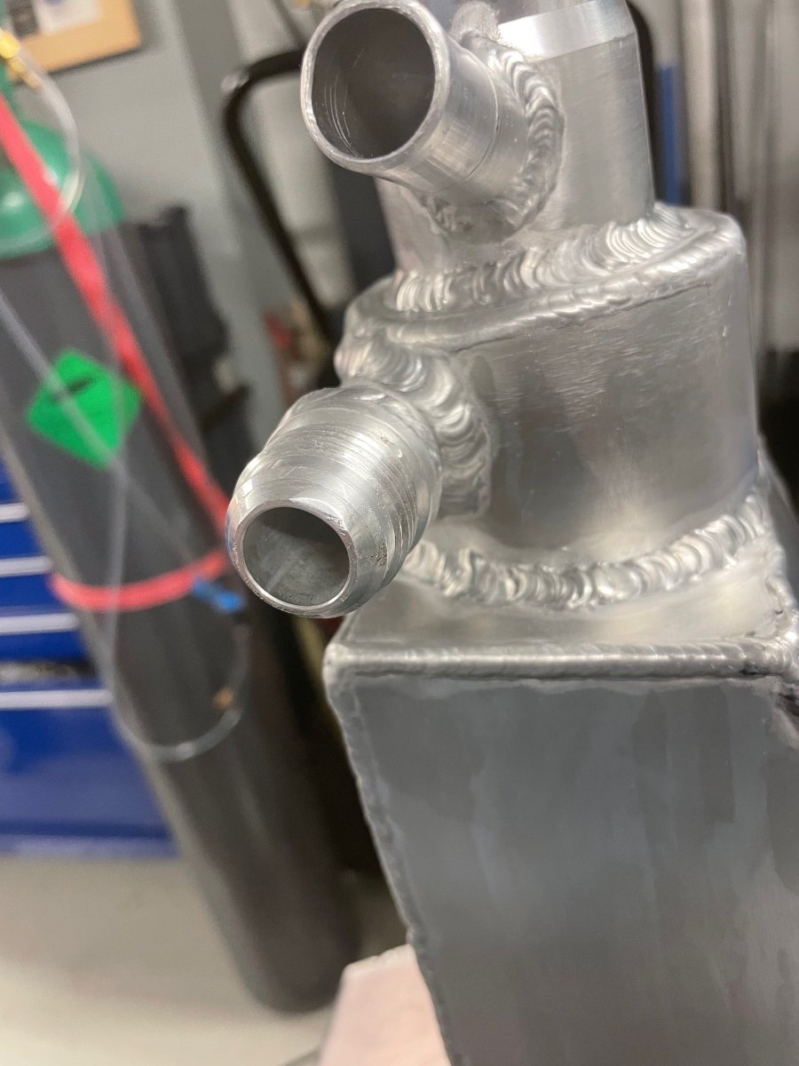
Some progress here as well. I’m still waiting for parts, So I cleaned up the engine harness a little and added the wires for the gear control unit. The harness doesn’t look very complicated, but I have to say that figuring out all the connections and sensors from scratch was a big job item on this car. I also started work on the chassis loom to add everything for the paddle shift system. My electrical ”tray” with its bus bars for ground, ignition and switched 12V make things relatively easy. The drysump oil tank is now out as well and cleaned up also from the inside - I had a few pinholes that need to be fixed. One large AN connector had trouble sealing and it looks like I have managed to dent the lip. Most likely the best solution is just to replace it.
-
Ok, the paddle setup has been ordered. I ended up with: - MME integrated gear actuator, which has its own valves and the GCU all built into one tiny package - MME inline valve and inline throttle cable blipper - MME steering wheel paddles for 280 mm flat Momo wheels - Meteor Motorsport compressor and bottle with actuator (only 2.3 kg) The compressor will go to the back of the car, so overall this should end up as a very clean installation in the engine bay. The engine (ECU) loom will require only 2 new connections: - Analog input for the ignition cut signal given by the GCU. The recommendation was not to use the CAN signal for this due to priorities. - Analog input for the gear signal. The MME GCU can send a simulated gear position signal (0-5V), so that the ECU can then also calculate the gear and eventually the AIM display can show it based on its communication with the ECU. I'll also pull this wire to the dash, so that I can have a separate gear indicator if needed. - The GCU will get the TPS and rpm info via the CAN bus, for which I had already a connector in the ECU loom from the dyno session.
-
Thanks Kitcat, much of this wouldn’t have been possible 20 years ago before forums like this or youtube - today anyone can pick up skills, that were previously very special. The sequential control has been very interesting to study and I’m leaning towards MME Motorsport from Slovenia. They have great documentation online, respond fast to questions, good looking products and a modern can based interface, that requires minimal changes to my engine loom and integrates well to my Ecumaster Black Ecu. It was very similar when researching Ecu’s - many of the Ecus from the Uk felt outdated and expensive with their RS232 interfaces and e.g. lack of built in wideband control. They most likely do their job extremel well once setup, but without any special experteese (here where I live) and minimal info on forums (as most are 10-20 years old tech) I was eventually super happy with my choice. Unfortunately the Ecumaster doesn’t yet have closed loop shift control, so I’ll still need a gear control unit alongside it. The plan is to retain the gear lever for normal shifting and neutral/reverse, while having paddles as an additional option for gears 1-6. I went with 2.30-0.87 gear ratios while keeping my 3.98 Ford diff.
-
I use 3, which makes navigating the engine hoist easy in the front and the car is very stable. I can recommend AC jack stands with the rubber base if you can still find them, two of mine are already under the ESCO brand.
-
The Go-Race column was 200g lighter than the original Lifeline, which was a nice surprise. The engine is out again and the Tracsport type9 has been sold, it will continue its life in an Escort - I’ll place an order for a new Sadev sequential this week.
-
I just came across this thread - this is going to be a brilliant spec, please post as many details as possible on the Sadev and shift setup...!
-
And a small upgrade - a new steering column from Go-Race arrived, the old one had some play in it. The first impression is great.
-
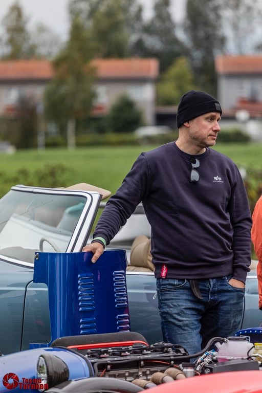
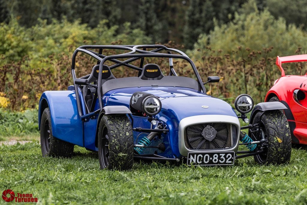
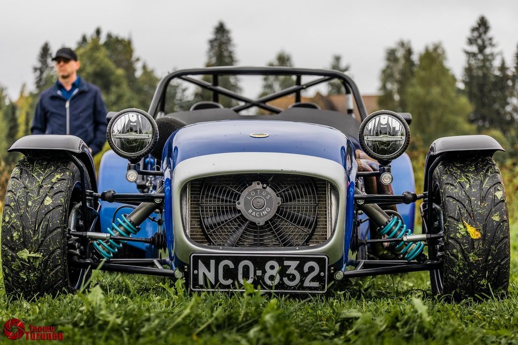
At a local car breakfast a photographer took some really nice images of the car - credits to Teemu Turunen:
-
-
-
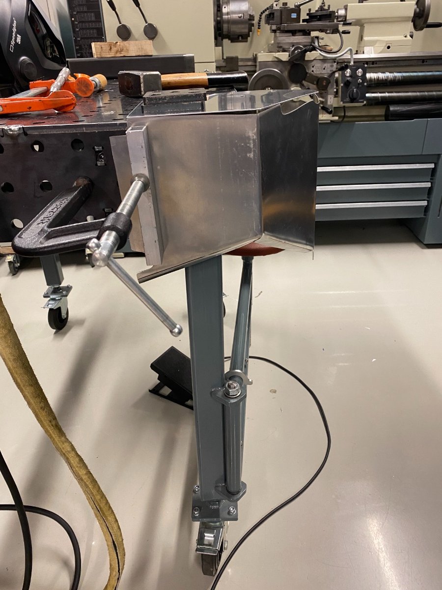
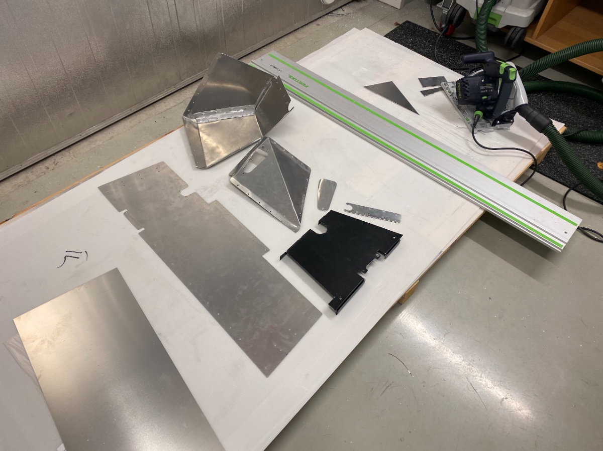
Copying also my RHD -> LHD post here to complete the documentation: Chassis: Imperial S3 The steering column lower and upper are usable on both sides The steering rack pinion can be rotated, but it needs machining a hole to the blanking plate. Remove C-lock ring, drill a small hole to the center of the blanking plate, use a punch to push the pinion out, take blanking plate out and machine larger hole to match steering rack connection and assemble -> done. I didn't have mounts for steering on both sides, so I had to do some welding. I cut the lower dash tube with the steering column symmetrically and flipped it over. The angles match. I cut of the pedal box as close as possible to the footwell The footwell on the driver and passenger side was of different shape. I used cardboard templates to replicate the original driver side, removed the original passenger side completely and built a new one out of scratch (1.5 mm 6061T6). Reshaped and fitted the pedal box and welded it in place Cut off the lower mount for the steering column (just outside scuttle) and welded it to other side Made a half moon cutout into the rectangular chassis tube to clear the steering rack Whether the steering column clears the engine components (exhaust, drysump, alternator...) or not is fairly hard to predict, but it can be checked with a string before starting. I had only a chassis to start with and could design everything around the new steering column location. So it is perfectly feasible to switch sides, but it will require serious fabrication and welding skills. I hope this helps someone in the future!
-
Hi Mike, the block is the aluminium version of the Opel/Vauxhall 2L 16v, which has an engine code C20XE -> hence the name Millington XE. Millington produces also new heads for this block and builds complete XE engines, however they are usually with a longer stroke and max out the cylinder bore to 88 mm for this engine. The original KS or Coscast C20XE heads fit perfectly as well. According to Millington I'm the first one to build a 2.0L with their block, which I selected mainly so I could use the Caterham HPC as my reference vehicle in our local re-registration process. The main advantage of the Millington block is a weight saving of 20kg, which takes place in the front of the car, and of course everyone else uses the option to increase the volume to 2.5L, which takes the engine effortlessly to 300-320 bhp. The project took 11 months from start to first drive, but I'm still in shakedown mode to get rid of a few fluid leaks, leaking header joints, re-routing a few chafing oil hoses... all the normal stuff that appears only after driving the car.
-
The tubes are similar on both sides, I left the original half moon cutout in place - after all who knows, perhaps someone wants the car in RHD format in another 54 years from now...
-
It started at its fourth try, then we ran it for 20 minutes at 2000 rpm to bed in the camshafts. After this it was off to the dyno, which didn't go too well - the throttle body wasn't balanced and then the engine started giving trigger errors... in the end we didn't do a single pull, it was a very expensive day. Trouble shooting continued back home and the trigger error was a lack of fuel - I had accidentally switched off the transfer pump, so my small swirl tank ran low and the trigger error was a miss-fire... The throttle balance turned out to be a much bigger problem. The TB idle bleed screws were not machined correctly and did not bleed, also the other barrel was smaller in diameter and had much more bleed around the barrel than the other. I welded more material and carefully fitted them into the body, it was 2 weeks of work to match them close enough, so that the idle bleed screw could be used to balance them. We did a preliminary base map so we could drive a little and the car passed its inspection - it was road legal again after 14 years in boxes! The radiator was leaking, so I ordered a new one from Caterham. I wanted to do a core exchange, but could find a core... oh well. I chopped the new radiator a little as well. The weight of the car is 510 kg with all engine fluids but no fuel. This is it - thanks for reading and questions or suggestions are always welcome!!
-
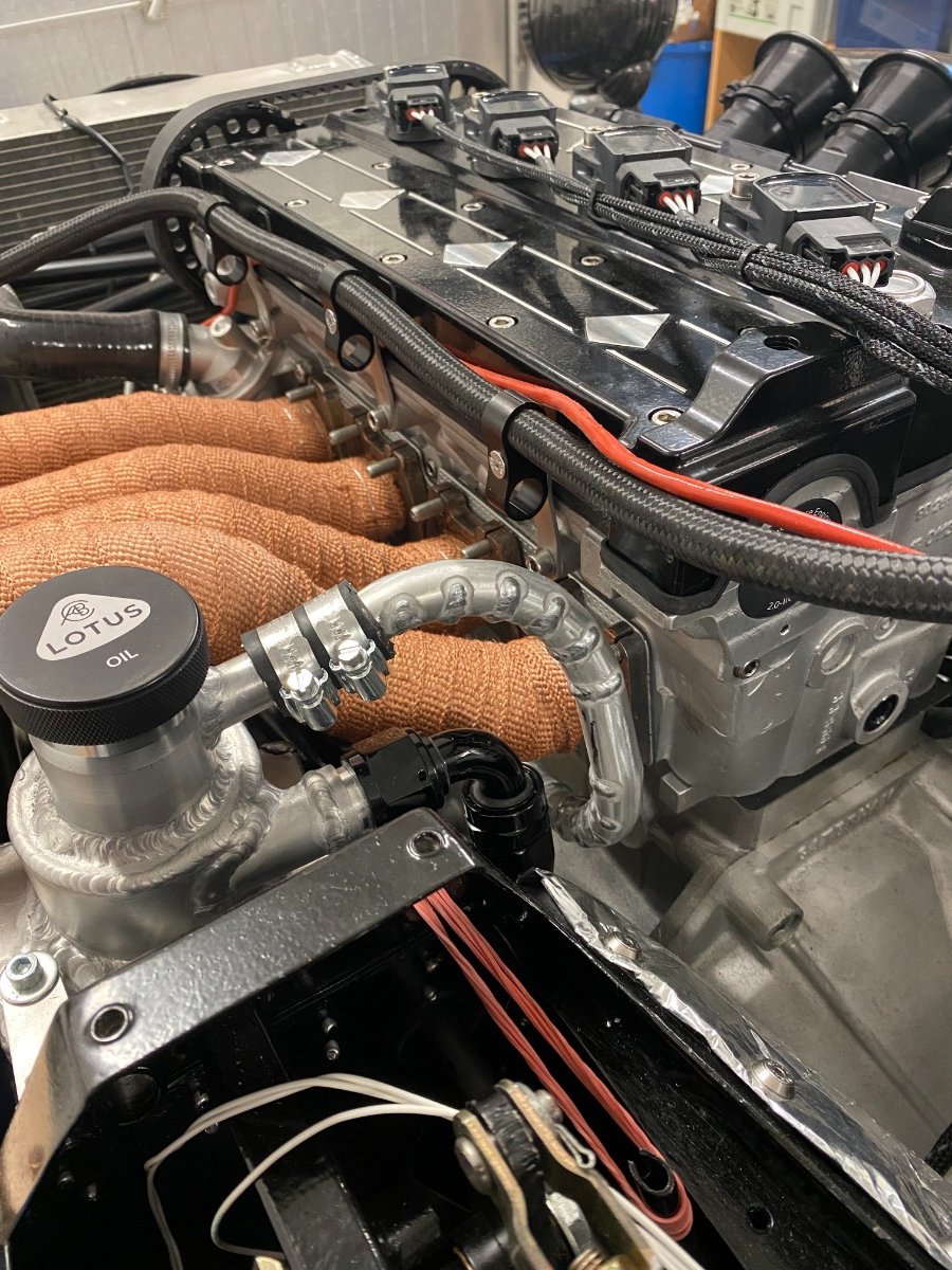
The intake at full throttle has a direct view into the cylinders! My injectors were EV14-580, with a measured output of 590 cc at 3 bar. This should be enough also for alcohol. Coil on plug is troublesome, so we made a quick adapter for the timing light. And it is ready for first start...
-
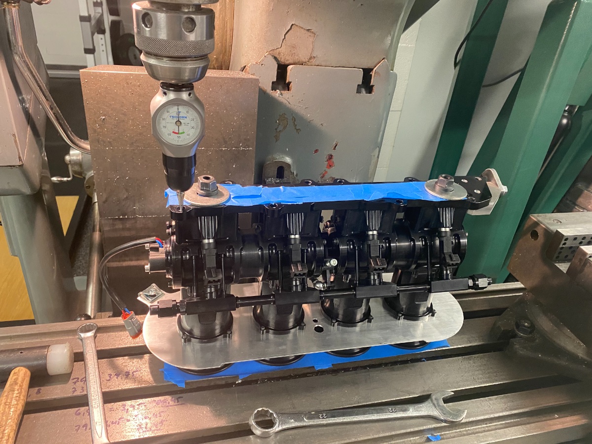
After waiting for more than half a year my roller body throttles arrived. I tried to fit hoses for the oil breather, but the routing didn't work. A couple of joyful hours with the saw and welder, as I don't have (yet) a pipe bender. I also got a sausage filter from ITG (ITG if you read this, please send me one with a logo that is not upside down!). I destroyed a nice chuck when making the backplate.. argh. Small jobs to complete were done now, like the brake light switch, heatshielding, TPS, throttle cable, alternator bracket... The throttle body was of course not aligned with my (ported) intake, so I elongiated the bolt holes a little for some up down adjustment. Good to have a large milling machine!
-
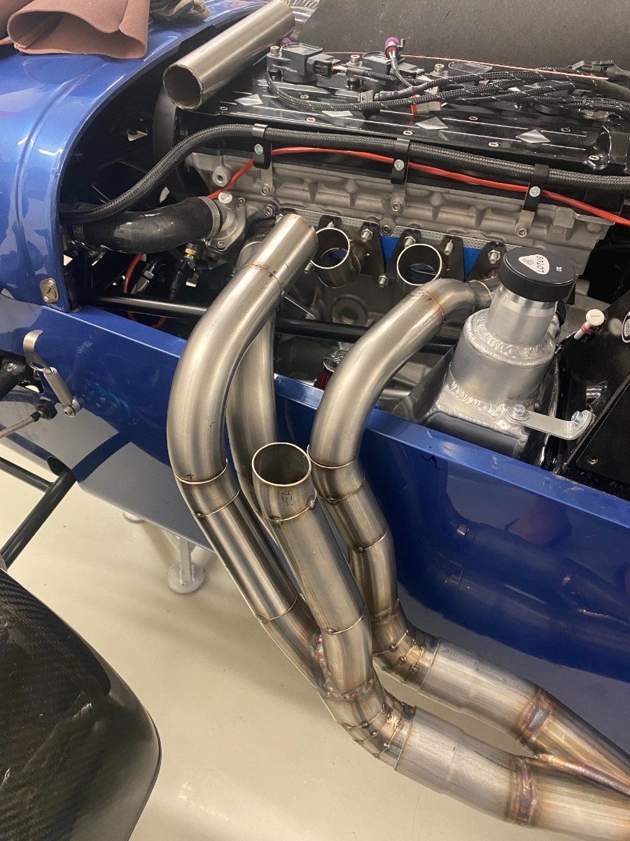
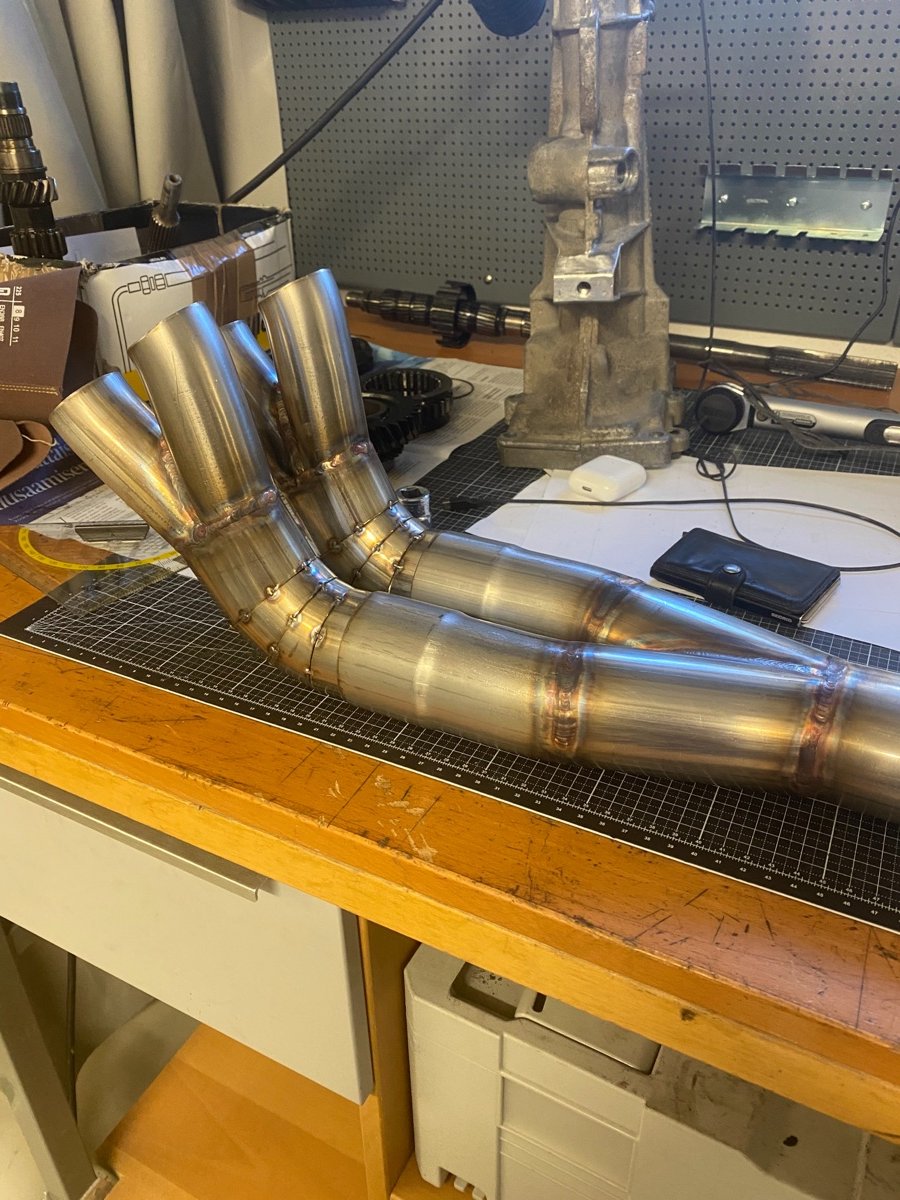
Next went in the water and oil lines. The belts took a few tries to find the right lengths (not easy to find in the first place). The drysump oil pump belt really has no adjustment, it just takes time to find the right distance (shims or spacers made to fit) and the tension is right, when you can take it off and back with your bare hands. I designed in my mind all kind of tension mechanisms, but there really is no need. At this stage I took a few months break, then mid June 2021 continued with the headers. Thru bonnet was the only option from space perspective. My exhaust numbers: Primary dia 44 mm Secondary dia 57 mm Collector dia 63.5 mm Primary length 570 mm Primary + y-joint + secondary length 850 mm I really couldn't find a lot of reference numbers for C20XE headers, the Lotus7 forum had an old post of some touring car headers, they had 48 mm primaries and the length was 685 mm for the primary and 940 mm for the secondary
-
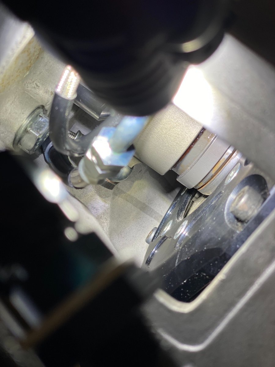
An4 for the clutch line and the bleed nipple to an easily reachable position. And it finally fits.. The engine/transmission goes in without drama, the engine mounts I attached when it is in place. The alloy case is thicker than the cast iron one, didn't take this into account. But there is clearance - some... and my new mount locates the bolts correctly, nice! And then, the clutch lines leak inside the bellhousing... Ok, one more lesson. Apparently the copper washers are these days too hard, so from now on I soften them always before using them. Glowing red (happens fast) and drop into water (yes, copper behaves differently). I had to pull the engine back out again, soften the washers and install everything back.
-
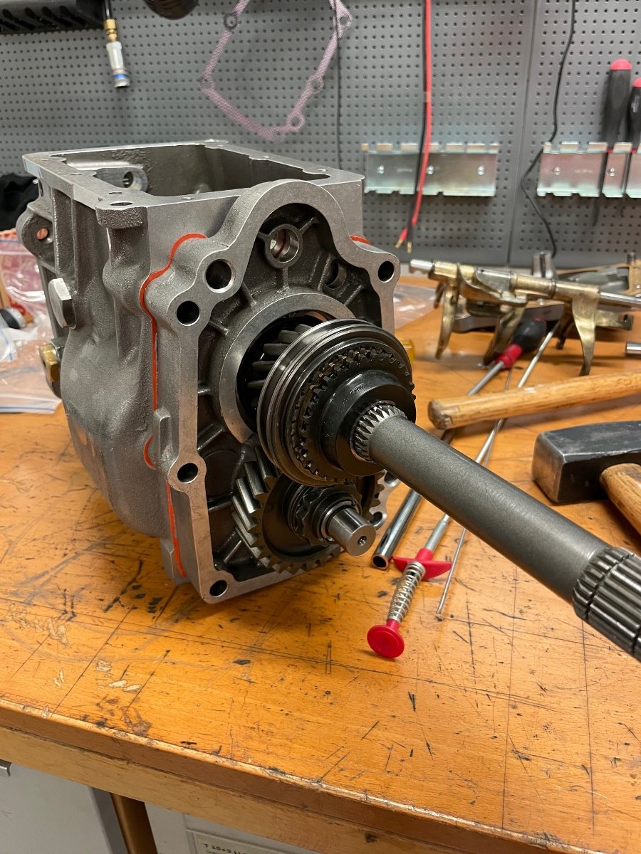
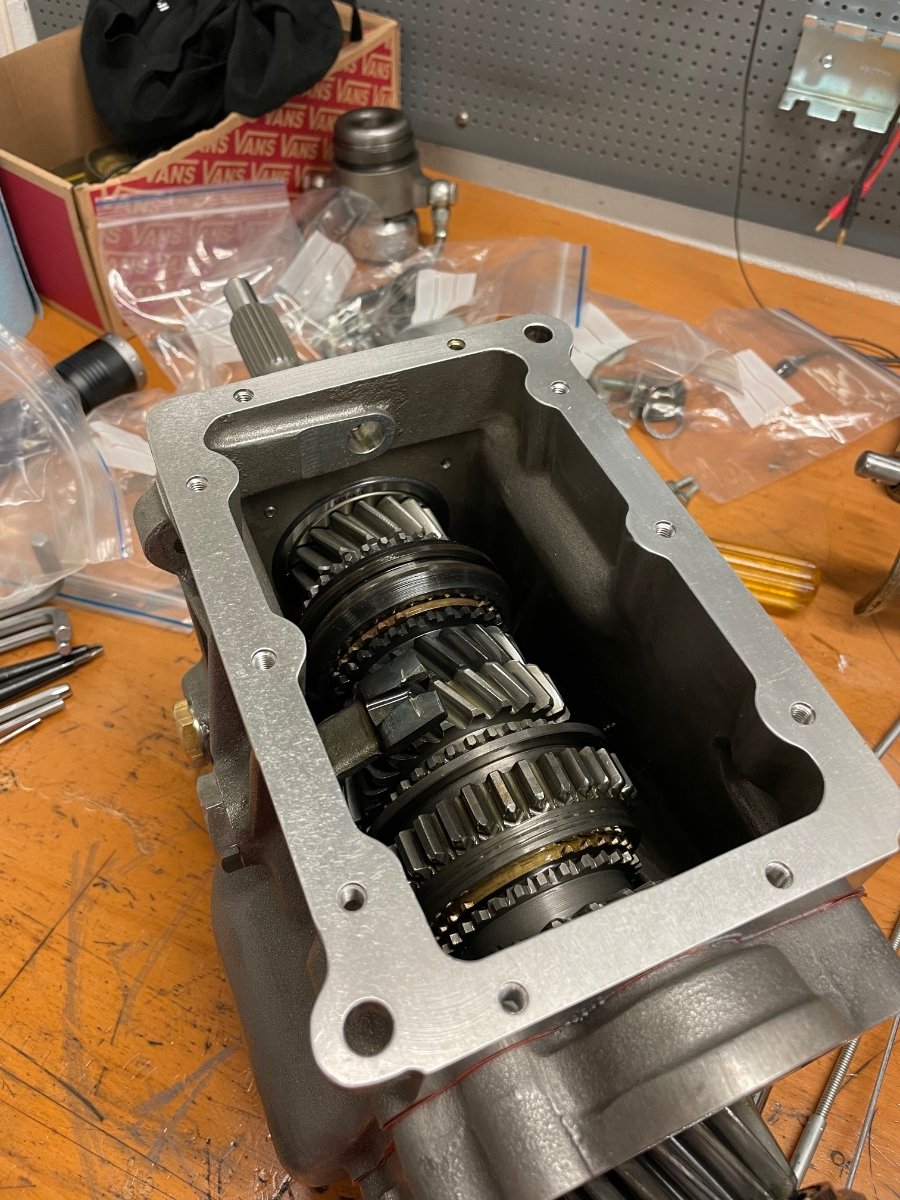
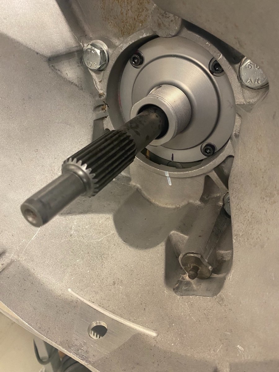
Some soda blasting made the tailcasting of the geabox like new again. I shortened the new input shaft and started with the assembly. No instructions, only this one gentleman in Youtube, who shows the disassembly and assembly of a type 9 - thank you!! 5,5 kg lighter, yey! A friend made me an adapter for the clutch, as he had nothing else to do for the weekend - thanks!
-
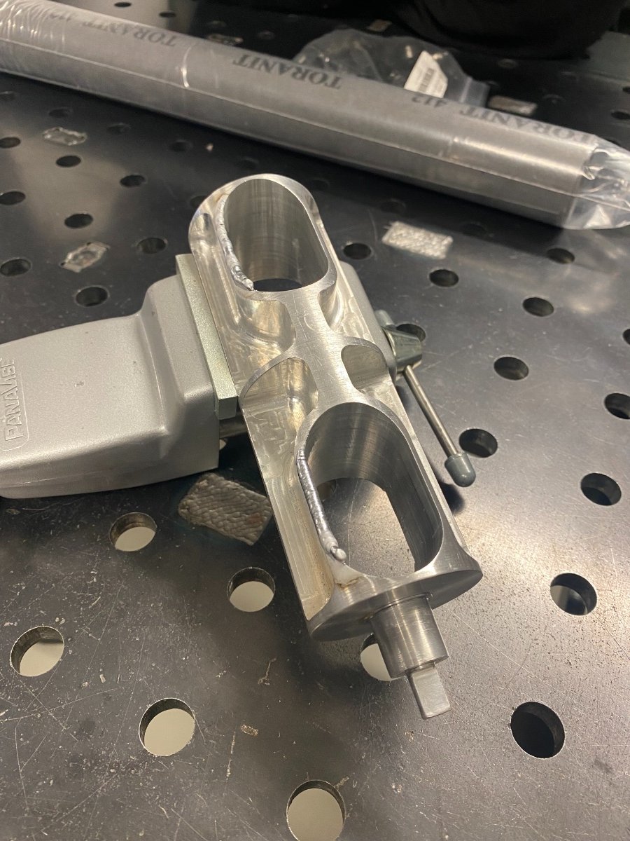
In parallel I started preparing for the headers, the exhaus flange needed some work. The port is oval and tubes are round, so this required some head scratching. I went for a 4-2-1 setup. I went with black steel for the flanges, as they warp less and used a special tig filler that works with both stainless and black. I connected the headers and the flanges with an inside weld, againg to prevent warping and creating a nice smooth intake.
-
Thanks Steve and Mike! Next was the mating the geabox - and it didn't fit. Type9 has two input shaft lengths and the C20XE uses the longer one cut down a little. Mine was the short one. And the hydraulic clutch didn't even reach the pressure plate of the clutch... this was a bad day. Next weekend I picked up a Type9 core for small money from a Sierra P100 diesel, it was from the early 90s and had the newest castings. The only issue was that the thread for the gearbox mount was destroyed. I also picked up some 304 stainless for the headers. I also ordered a full set of gears, a new alloy case, semi-helical gearset, needle bearing mainshaft and some other bits from SPC / Tracsport in the Uk.