Rosteri
-
Posts
179 -
Joined
-
Last visited
Content Type
Profiles
Forums
Store
Articles
Gallery
Events
Library
Everything posted by Rosteri
-
And a short video with some sequential action… IMG_6137.MOV
-
Thanks CarlB! The car works nicely and is a blast on track, so I suppose it is time to try and finalise the build. I still have four items on my mind: 1) Extra head support for the Tillet seats. I have the parts Caterham supplied with the roll cage and... they just don't make any sense. I'll try to fabricate something decent. 2) Safety fuel cell 3) Integrated fire extinguisher system 4) Less noise When I started this car I repaired my old tank and integrated a surge tank into it (basically copied the Nuke Performance CFC unit), so when I started looking at the fuel cell options for Caterhams they all seemed like a step backward from my current setup with external pumps etc. Nuke has collaborated with Pyrotect and this combo looked really nice: https://www.nukeperformance.com/product.html/pyrotect-pyrocell-elite It would be super easy to replace, as I can re-use my in-tank fuel pumps and all electrics and plumbing is 1:1. But the standard tank sizes won't fit, so I sketched up a Caterham tank that would work with the Nuke CFC ATL unit (15 mm higher than standard Ford/Vauxhall tank). Pyrotect responded super fast and their price for my custom tank was very reasonable -> order placed! caterham_tank_v2.pdf Then regarding the noise I ordered a new 750 mm long Raceco titanium silencer with a central 70 mm center inlet, which hopefully should do the trick.
-
If they are cut on a machine to the right spec, then there is no need to lap valves - new car engines aren’t lapped either…
-
Over 10 deg from horizontal to avoid condensation dropping on tip, it is also fine to mount it fully vertical on a 7, as there are no hot air pockets since it is in free air. If you can select the heat up sequence I recommend a conservative profile (slow heat up), so the pipe clears of moisture before heating starts.
-
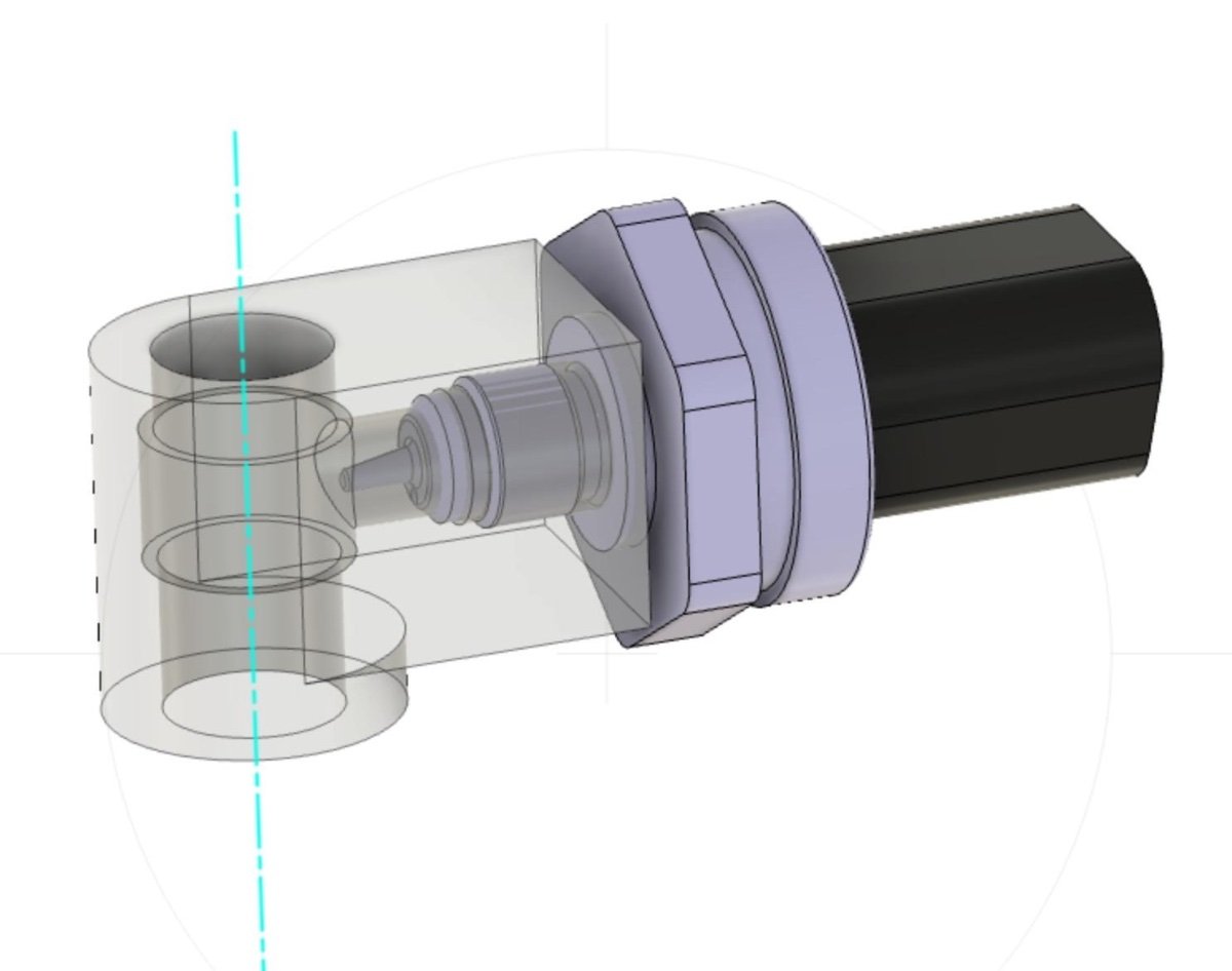
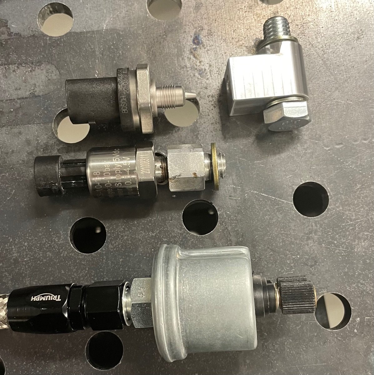
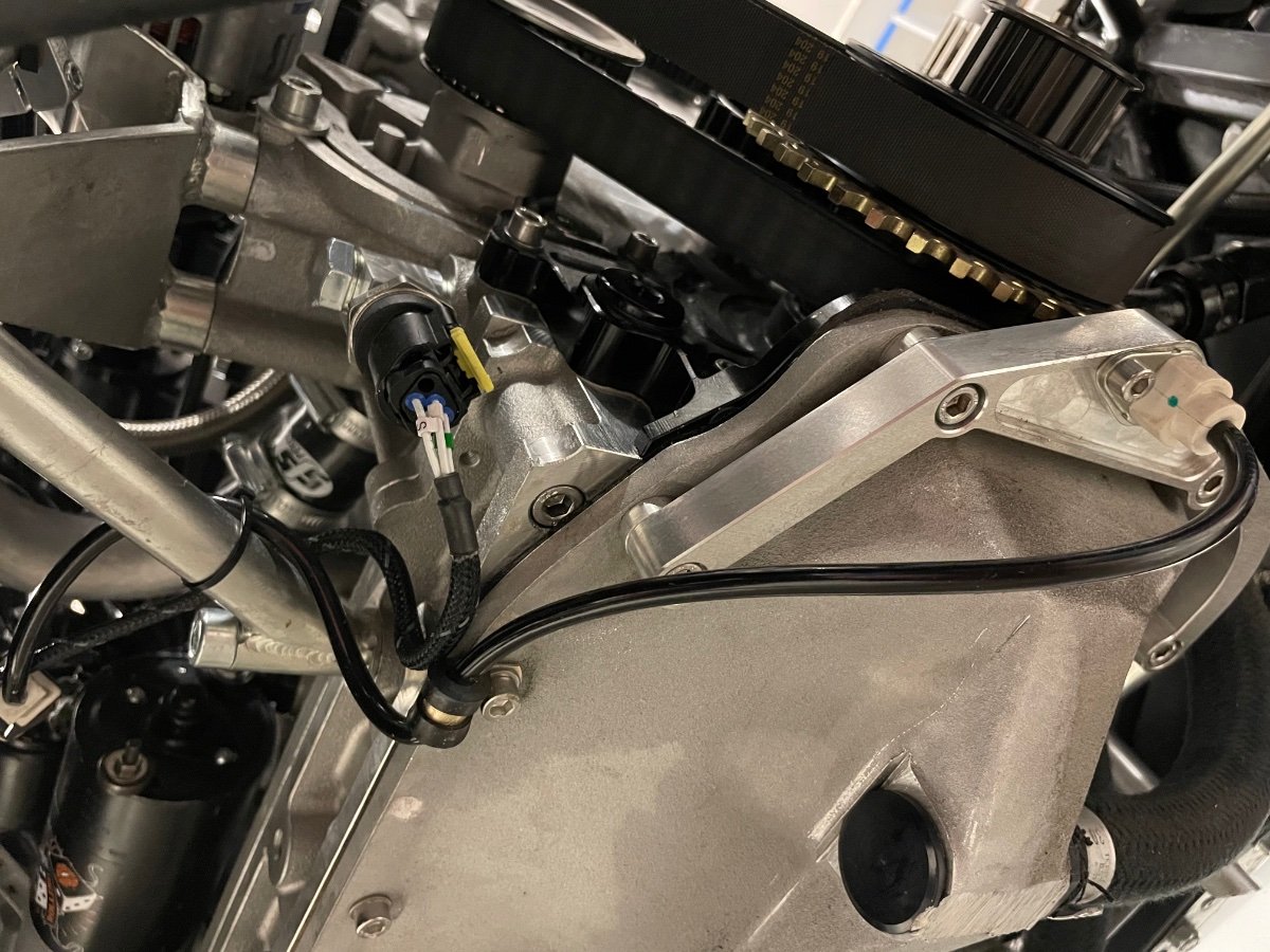
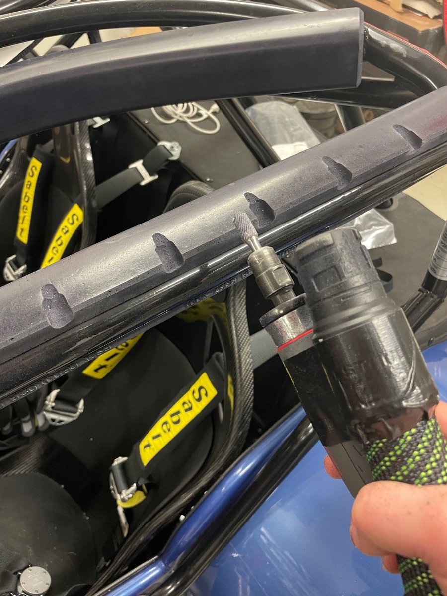
Datasheet for 0261230340: https://www.bosch-motorsport.com/content/downloads/Raceparts/Resources/pdf/Data Sheet_70496907_Pressure_Sensor_Combined_PST-F_1.pdf I designed and made a 90 degree Banjo. The sensor is M10x1 and the Millington oil port is M12x1.75: Bosch on top, Variohm/clone that failed in the middle and old style Bosch below: It took me a while to figure out how the new Bosch connector works. The installation from below the car:

-
At the moment I do believe it is just a sensor issue. The oil levels in the dry sump were normal, so suddenly sucking air doesn't seem likely, also if it was something engine internal related, then it would not repair itself. I will also measure the wires, when I change the loom connector for the new Bosch sensor.
-
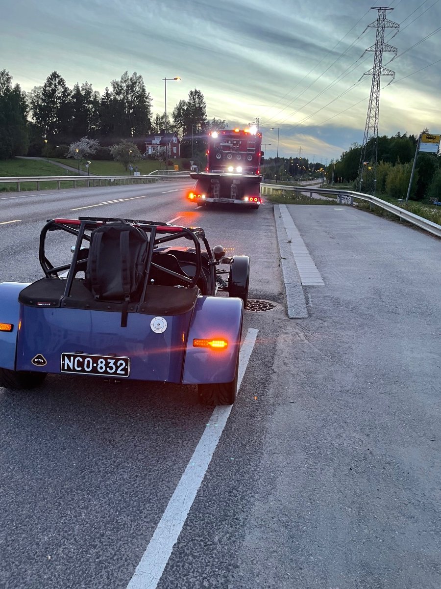
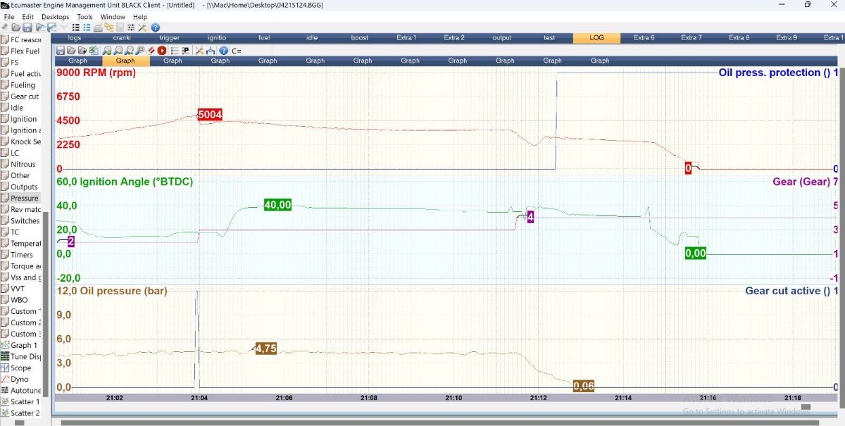
I was out for a drive last night and the engine suddenly shut down with a low oil pressure warning. After a check I tried a re-start, nice idle, no noises but also no oil pressure. So I ordered a ”taxi” back home: The engine log shows a clutched shift from 3rd to 4th gear, and right after the oil pressure starts to go down and the oil pressure protection function then kills the engine. Back at the garage I checked the oil pressure with a cordless drill and everything was back to normal... My sensor is a Variohm type (but not an original) and apparently these knock-offs are no good, when mounted directly to the block. No Variohms in stock anywhere near, so I guess I’ll switch to a modern Bosch sensor (0261230340). I’m not very excited of a remote connection to the block, let’s see how I’m going to do it now.
-
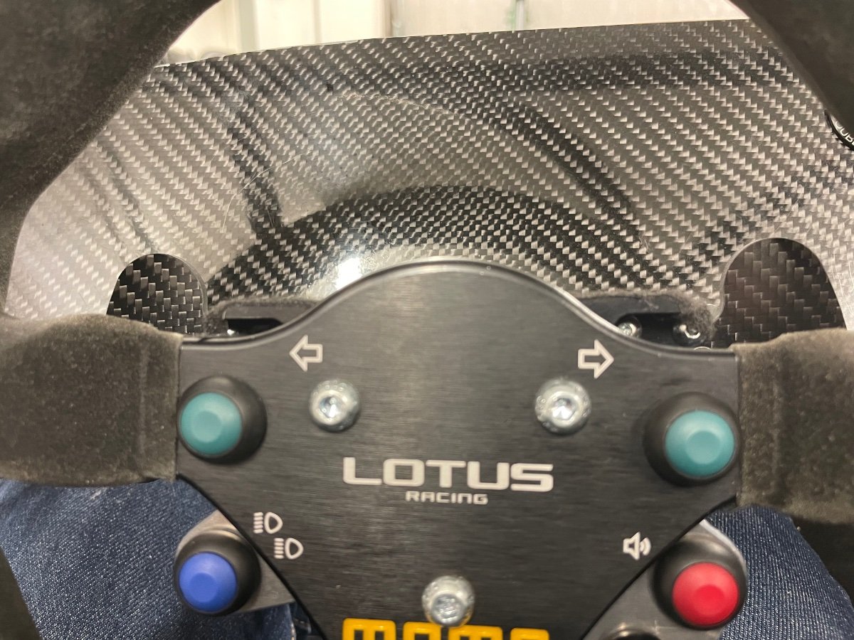
Working on the shift settings for the paddle - especially the downshift has been quite interesting to configure. We start to be ready for the first track day. downshift test.mp4
-
Well, after a few hours of staring, I decided to re-use the alternative pivot points meant for the throttle pedal to mount the stop. My first idea was to use the floor, but I just could reach there anymore…
-
Hah, I tried that and no luck - FIA pads are much too hard! Unfortunately there is still stuff to do, the main item for this summer is a missing throttle pedal stop. So far I have been using a stop at the TB end, but I think I now know the movement range and can figure out a final arrangement so I don't rip the cable off in the heat of a battle...
-
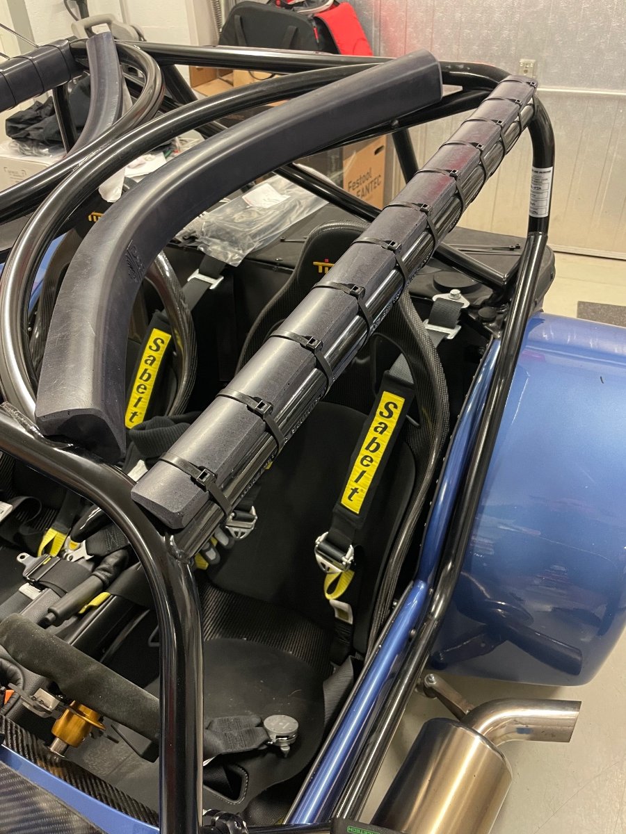
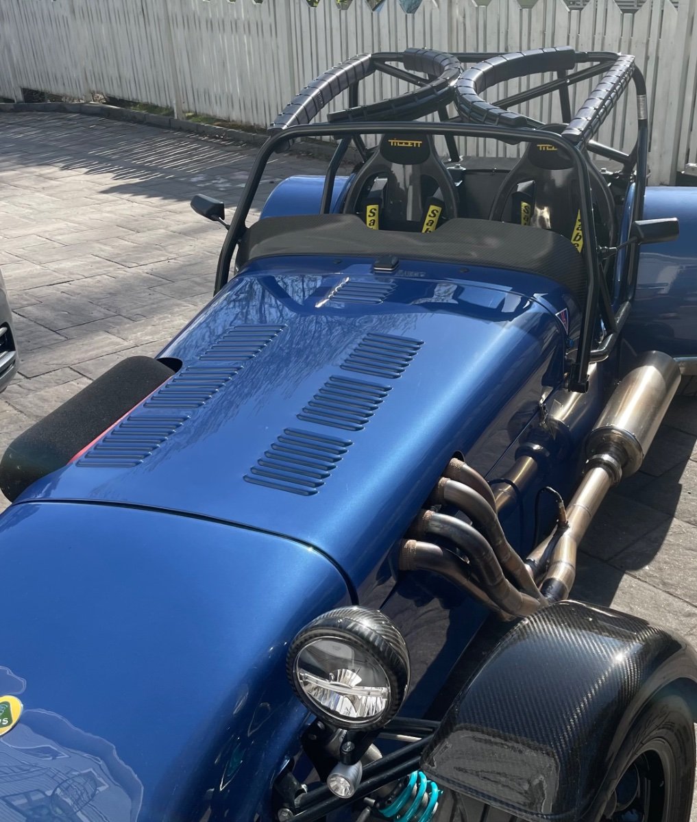
Rollcage pads - again one if those jobs, that I kept pushing into the future, as I couldn’t find any decent way to attach them. I went for cable ties, but tried my best to at least recess the heads. With a custom fabric cover they will look fine.
-
I am just referring to how gears go in in general - the stick movement is converted to barrel rotation and it makes a loud clunk when gears are changed, even when the engine turned off. So this is not yet about the tuning or manual vs paddle.
-
I now have the first part of the shakedown behind me - first oil change (50 km) on the Sadev is done and around 200 km driven in total. I have shifted both manually and with the paddles, however only with the clutch at this stage. The paddles are amazing and stop and go traffic is actually super relaxing, as shifting is now totally effortless. Manual gear shifts require quite a bit more force than my Tracsport type9, the sound levels are relatively similar when moving, but the box makes a very loud clunck/bang when a gear goes in. Part throttle etc feel all the same, so for me this box is perfectly usable for my ”everyday” driving. We have not noticed/heard the compressor running during driving, which is great. The only issue so far is my throttle cable gradually slackening, thanks to the pneumatic blipping on downshifts. I need to fix that. Next we will do the first shift tests under power. MME has full logging features built-in, so we should have good visibility of what is going on.
-
I have also shelled money on a few parts from Westermann - 1) instrument panel, required significant trimming to fit, it is ok, but the surface finish is not perfect 2) hard half doors, required extreme effort to fit poorly and no instructions how to attach (and my shoulders are too wide anyway, I can’t use them), 3) carbon front indicator brackets, which had the lamp holes drilled totally off on both (got my money back on them and made my own, just binned them the other day). All seems very handmade, which is fine, but if you sell them, then at least make them until you get it right.
-
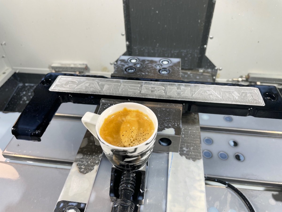
A nice start into the day today, as I managed to figure out how to machine a Caterham logo from a vector file to the spark plug cover for a fellow 7 owner. I imagine this will be a usefull capability later on.
-
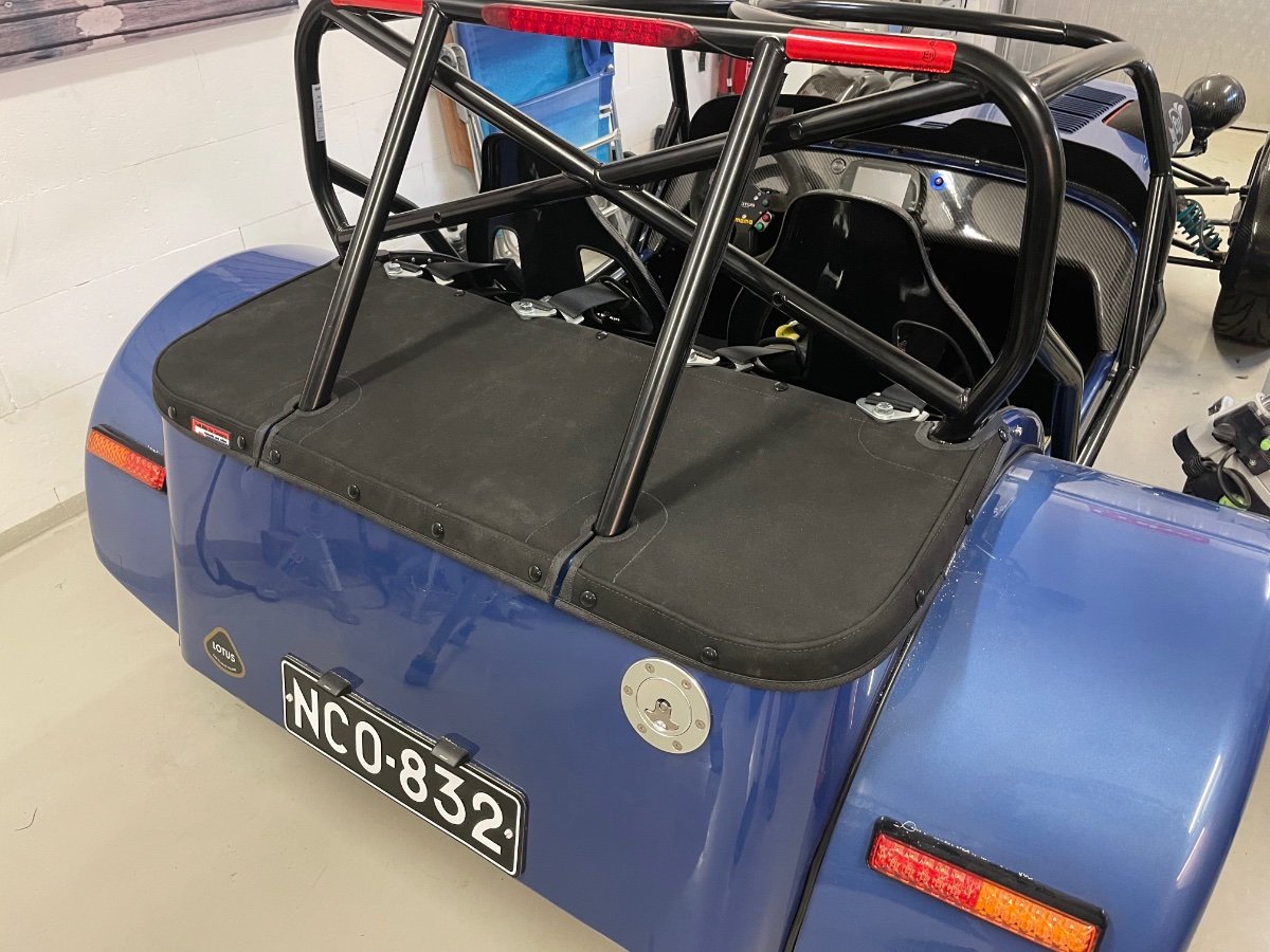
I mounted the boot cover, which has been waiting for the right inspiration a year now. Also warmed up the engine, no issues, apart from a wash and the weather the car is now all set for the upcoming season. IMG_5705.MOV
-
There are actually a few videos on using a Cricut for gaskets, it looks like a great little tool!
-
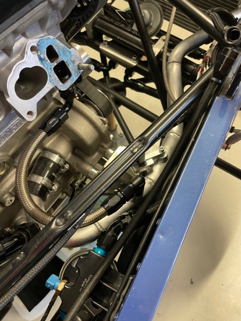
Thanks MV8 - a metal gasket that would stay in place is a very good suggestion. The upper port is for air venting (from the original intake manifold) and the lower port is circulation back to water pump, when the thermostat is closed. I tapped the circulation connection directly to the head, so both could be blocked from my perspective, however I can't fit studs as there is no room for nuts on my throttle body (I use socket head bolts). If I would use flange sealant for the metal gasket, then it would most likely be ok also without studs, as it would be bonded at least a little when the throttle body is removed. I'll definitely take this into consideration next time I remove it.
-
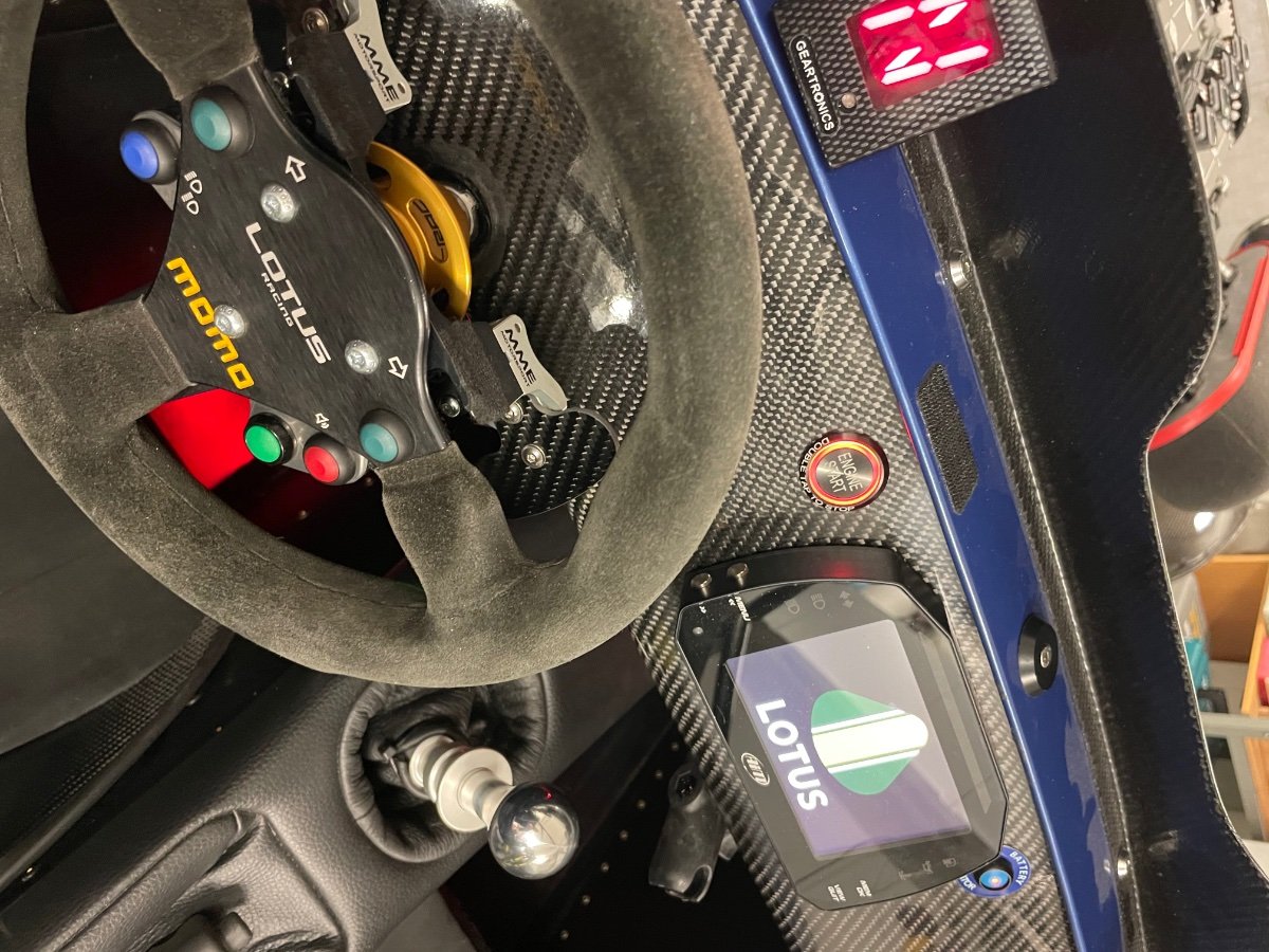
Fluids are in, the oil system primed and the oil pressure checked ok ->the car is ready for a first engine start 2022. A suggestion for anyone doing a custom instrument panel -> I combined the alternator light to the start button illumination. It works perfectly, as it goes dark when engine is on and all ok. And a short video on throttle blipper for downshifting, it is quite violent: IMG_5658.MOV
-
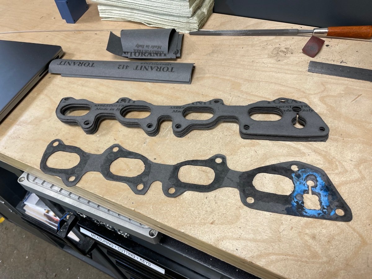
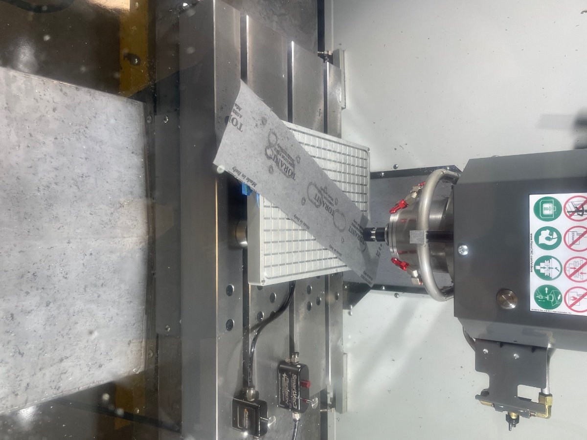
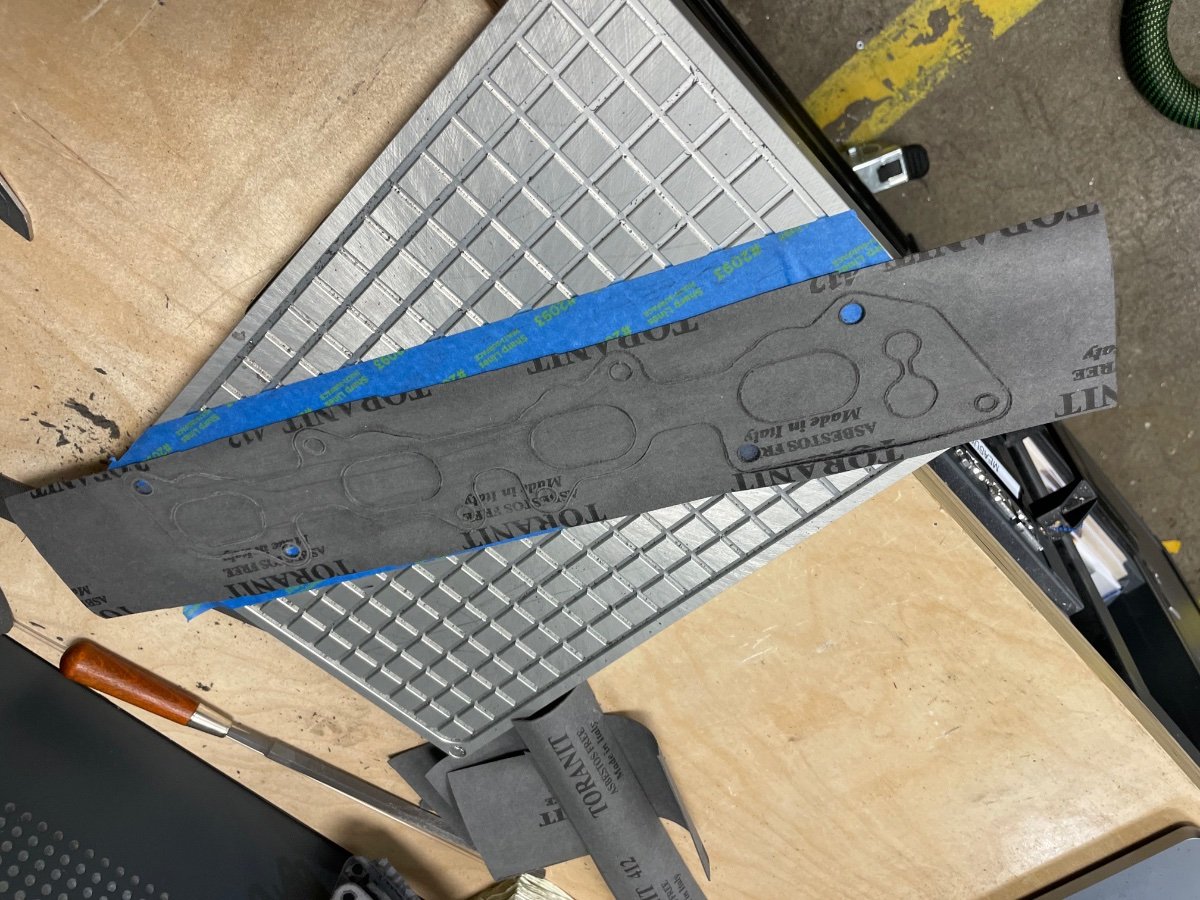
I did an interesting trial today - my heads are ported and I need gaskets with bigger openings, so I’ve been making them with a knife. Unfortunately I need to seal a water port with some extra adhesive, so everytime the throttle body comes off, I have to make a new one. Lot’s of work. My record was 3 pcs in one day during the troubleshooting period… Today I tried to cnc cut them, as I’m currently missing access to a laser. Internet claims you can’t machine gaskets directly, as there will be a burr / it will rip. I did a few trials and a 1 mm cutter at 10 krpm worked fine, I just used double sided tape to secure the gasket and had a 0.15 mm air gap for the cutter not to touch the table. There is a burr, but it comes off easily with some sandpaper. Finally some stock:
-
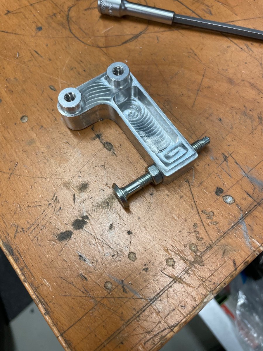
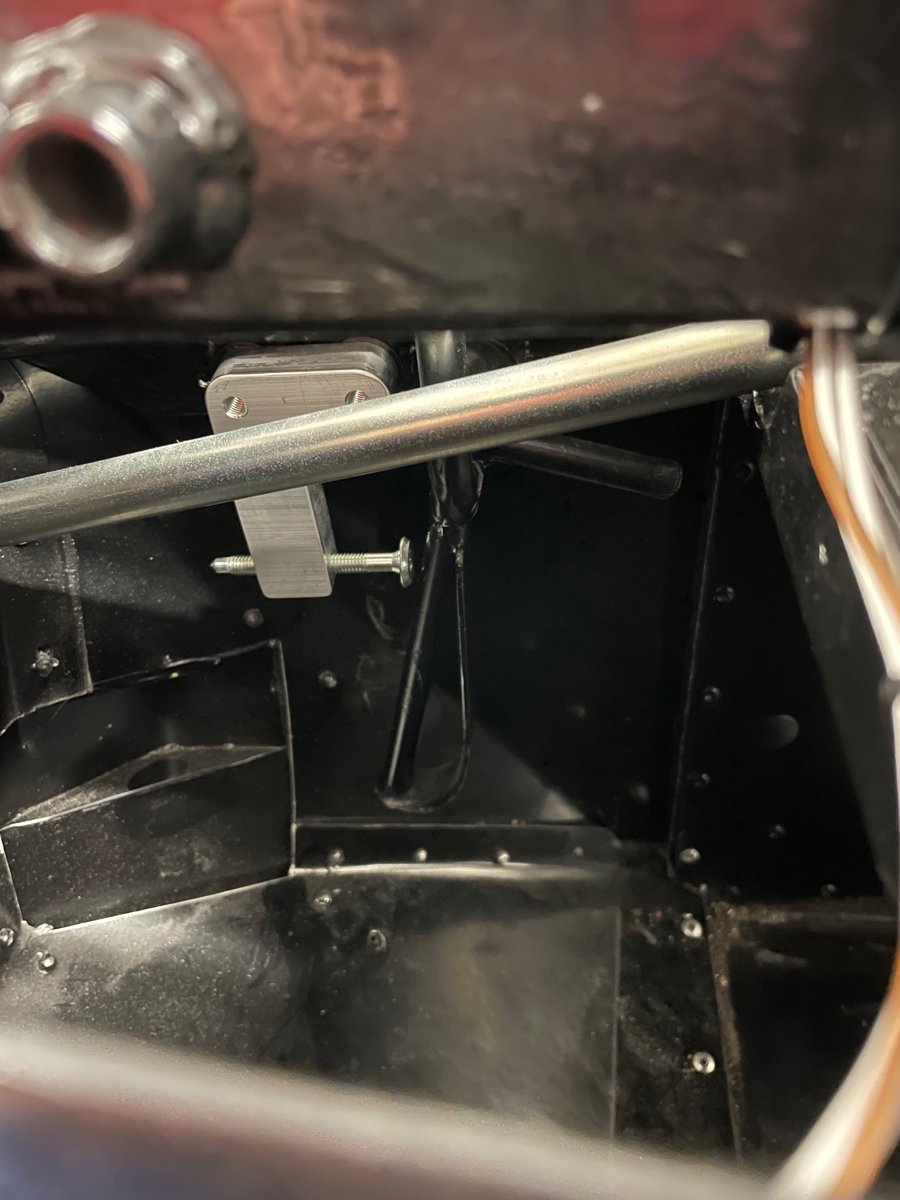
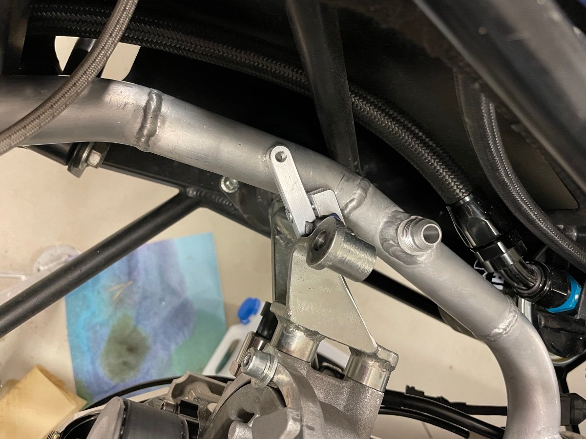
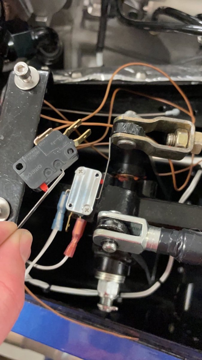
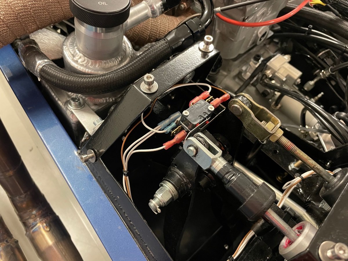
A few small things today… my water pipe was rubbing a little on the engine mount, so I made a bracket, that clamps to the engine mount. I just need to weld a boss to the water pipe and I can then support it: And I made a tiny adapter so I can mount a second microswitch for the clutch on top of the brake switch: And the engine logger is wired and mounted under the dash with adhesive velcro. The lights are blinking continuously like crazy… I guess I’ll just tape them over or something.
-
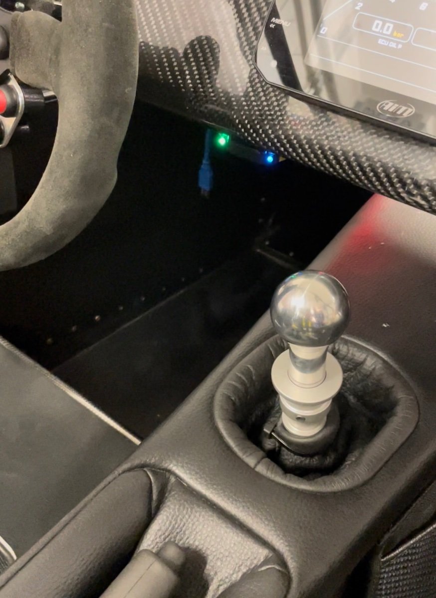
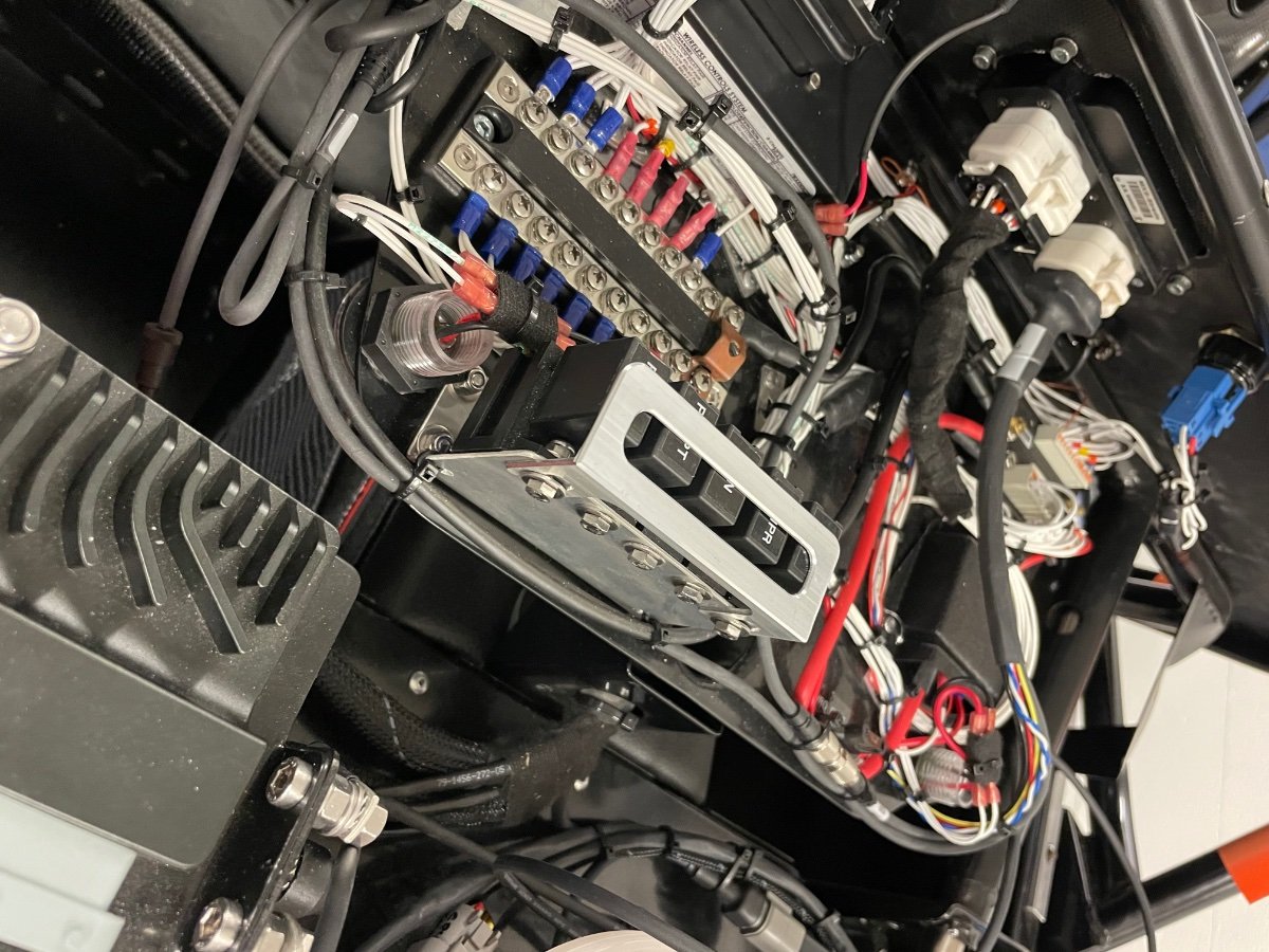
Bracket day, Project Binky would be proud… gear display: Gear position connector: Bracket to secure relays so they stay in place: And a Ram Mount for the phone attached to the underside of my electronics tray (right of shifter): The gear display feels a bit too bright in darkness despite its light sensor, so I think I’ll take the scuttle off once more and add a hidden switch for it. And to delight Porsche owners - have a look how the carbon weave aligns! Unfortunately I don’t have any colored stitching on the dash to really make this car something crazy… 😎 And the Ecumaster ECU datalogger arrived - I just need to decide where to place it. My engine loom has the unused connector for VSS, so I could modify the wiring for the logger. It came with a 4GB memory card, which should be good for 120 hours of data.
-
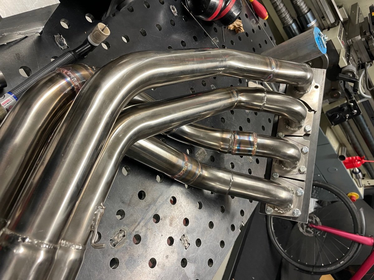
Bending headers isn’t an option, it is just not possible with home equipment. I helped this weekend another 7 owner fit some old headers, that were not a pair - we had to cut and reweld.
-
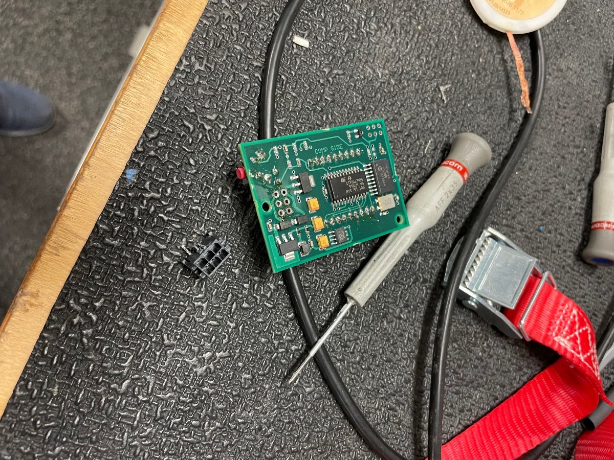
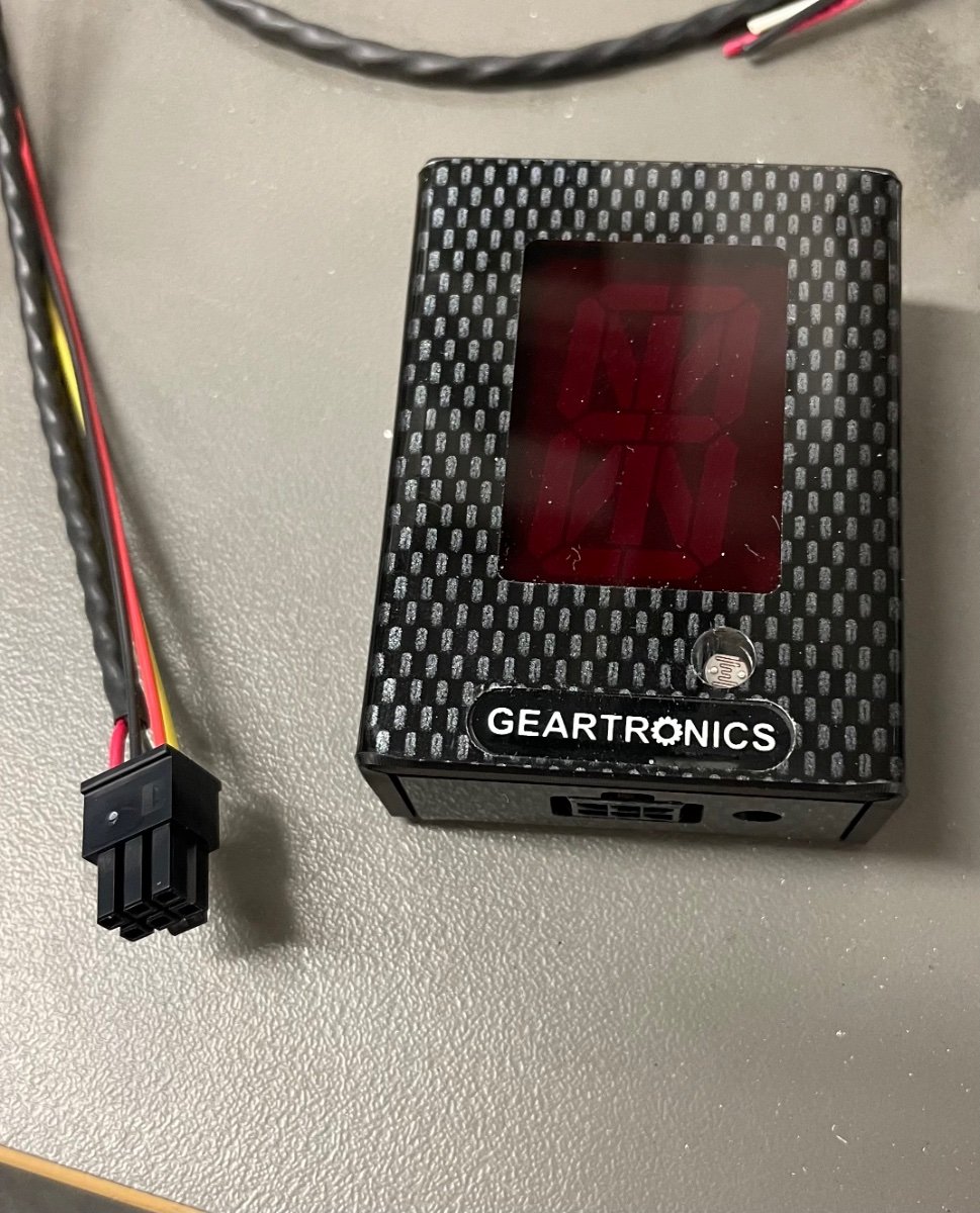
The bottom output was anyway a problem with the gear display, so I removed the connector completely and soldered my 3 wires directly to the pcb, which allowed a back exit. Bracket next.
-
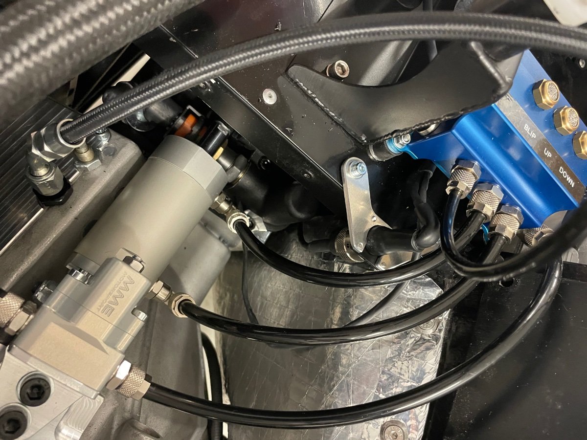
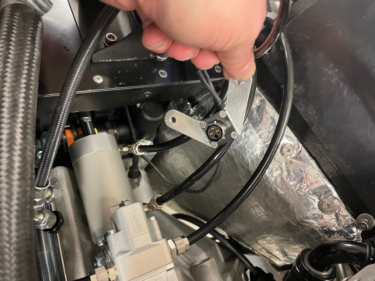
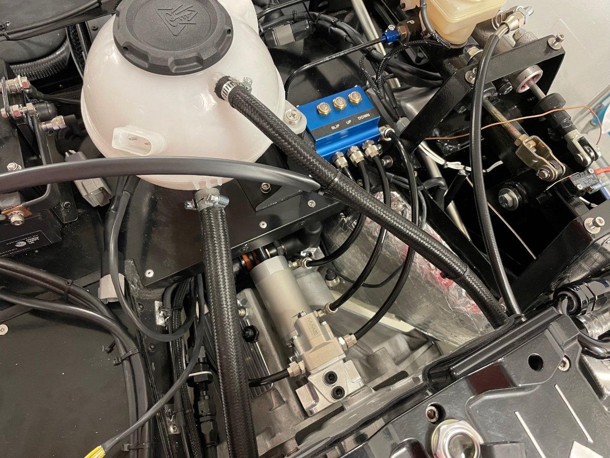
Pneumatic hoses are now connected - next is a bracket in front of the valve block for the gear position sensor connector, also my clutch hose is 10 mm too short, so that needs to be redone. Once the clutch is bled and leak free, then the rest of the hoses and starter go back on next. The Geartronics gear display arrived today and I’m not impressed. A basic Molex pcb connector that is preassembled. I need only 3 of the wires, and I can’t get them out, while my ocd permits to just cut them off... Also no features are present for mounting the case. And the case is fake carbon.