copy.jpg.dd4bdbb41ccb3ea8a585d1ad217ef61b.jpg)
.jpg.da03509438cc84820b8cf5d64db570ab.jpg)
Austin David
-
Posts
422 -
Joined
-
Last visited
Content Type
Profiles
Forums
Store
Articles
Gallery
Events
Library
Everything posted by Austin David
-
Not at all stupid! I had already played "boot carpet tetris" so I was prepared for two similar-looking-but-not-identical parts. Without the carpet they were *perfect*. With the carpet they're a little too wide -- exactly one carpet-depth too wide. NBD, just funny. I assume they make one size of mat, and not everyone gets carpet. I put the seats in today and see that the frame member is under the seat, so that rubber mat entirely consumes the actual footwell. Clever design. Also I've officially upgraded from "noisy collection of parts" to "noisy loveseat."
-
Tunnel carpets are in. This is a standard S3; there's a frame member across the floor. The floormats are cut to JUST fit in the trapezoid between the tunnel, front of footwell, side, and that frame member (about under one's knees). Unfortunately the carpet also comes down to the floor, which makes the floormats too big (or the carpets too long). For now they're folded up a little at the sides, I'll hold off a bit before cutting anything.
-
Carpet: apparently I ordered "more carpet." There's a biggish panel for behind the seats, not listed in the Ikea 2.0 manual. In 2015 it's the "rear bulkhead carpet" or "seatback carpet" (p145). I used thin carpet tape, not glue. Had to unscrew 6 "poppers" holding the boot cover, tape this big panel to the back face of the cockpit. It will need some trim around the belts (I have 3-point / retractable). The top edge of this section is matching vinyl. I pulled that into the boot area, held it snug, and folded the two outside corners over. This exposed the screwholes for the two outside poppers, which I used to fix the position of the boot cover. With that in place I was able to seat the center 4 poppers through this vinyl flap. One at a time, holding it nice and snug, and already centered with the tunnel, the seatbelts, and secured (a little) with carpet tape. The screws are pointy enough that they went right through the vinyl, no issues. I've also got a whole tangram set for the rear boot. I've puzzled that out (pun) and I think every piece will need to be trimmed. Have not yet decided if I will actually apply every piece. Josh (RMC) recommended the carpet tape, I love it. It sticks to the bulkhead or boot floor, and holds the carpet BUT is also easy to reposition. Edit: the seats pretty effectively block the belts and where they interfere with the carpet / feed into the retractor. If you want to trim, do it before installing the seats. Also it may not be obvious for the less-initiated, but the seats take up every bit of available space -- do them last. Kinda like the transmission and duratec (at least in S3): the car is essentially the bare minimum, snugged around a transmission, motor, and two seats. They touch the carpet on both sides, effectively block the harness attachments, and press the buckle against the cutout in the tunnel. I've taken to telling people it's basically a kayak.
-
Yeah, I lived out there for 15 years. I don't miss the 2-hour commute, but I definitely miss the weather and the roads.
-
ok mr KnifeySpooney I will straight up buy you a burger at Alice's, if you drive. And fries and stuff. tl;dr the sender was wired backward. Read on for some data. I tried running a dedicated ground to the sender wire (submarine chassis / screw terminal) and the temp gauge shot UP. Which is nuts, right? The original wiring (as I assembled it a week-ish ago) was with the loom single green wire -> submarine chassis, and loom two black/yellow -> sender center. So I flipped it and the temp read more like I expect: slightly above 100C (indicated) when the fan kicks in, drops slightly below 100C (indicated) when the fan finished. While I was over there I also took ohmeter readings for a few fan cycles. It was very consistent. The fan consistently led the temperature / resistance swings (that is, the submarine reading trailed the ECU behavior and fan cooling) so I assume the internal temp reader is up front / upstream, cooling action is upstream, and the submarine sees cooler water about 10 (ISH) seconds late. Fan kicks in at 134 ohms, the reading drops as low as 131 before it starts rising. Higher reading == lower temperature. I haven't found a good table for this sensor; autometer's article says 210F (100C) is 123 ohms, so maybe this was south of that a little? Fan cuts off at 136.5 ohms, and resistance rises as much as 144 (cooled fluid circulates to the submarine) before it starts falling again as the cycle repeats. I observed this several times very consistently. About the sender: I just again scoured the 2015 and v2 Ikea manual and can't see where the wiring is mentioned. I must've incorrectly ASSUMEd the single green wire was the earth and the two colored wires were the signal. I further assumed it didn't materially matter, since it's a resistor and not itself connected directly to the chassis ground. ¯\_(ツ)_/¯ I put it back to the "original" connection and confirmed it was as before (reading ~ 110C). The "other" way has it reading more inline with expectations at 100C when the fan cycles. Anyway, that article got me to first double-check the ground which pointed out the wiring issue. Onion rings on me (eventually)
-
Confirmed my temp sender+gauge reads about ~15C high, using an external IR sensor against the water rail, block, and hoses at the submarine. Fan cycles correctly (kicks in around 95C external read on the water rail). Hopefully I can calibrate the gauge, but failing that it's either a new sensor or some shenanigans with a trimpot.
-
.thumb.jpg.885191d302e6c3704c848a8f5ac3a612.jpg)
Bonnet storage during maintenance?
Austin David replied to Austin David's topic in General Sevens Discussion
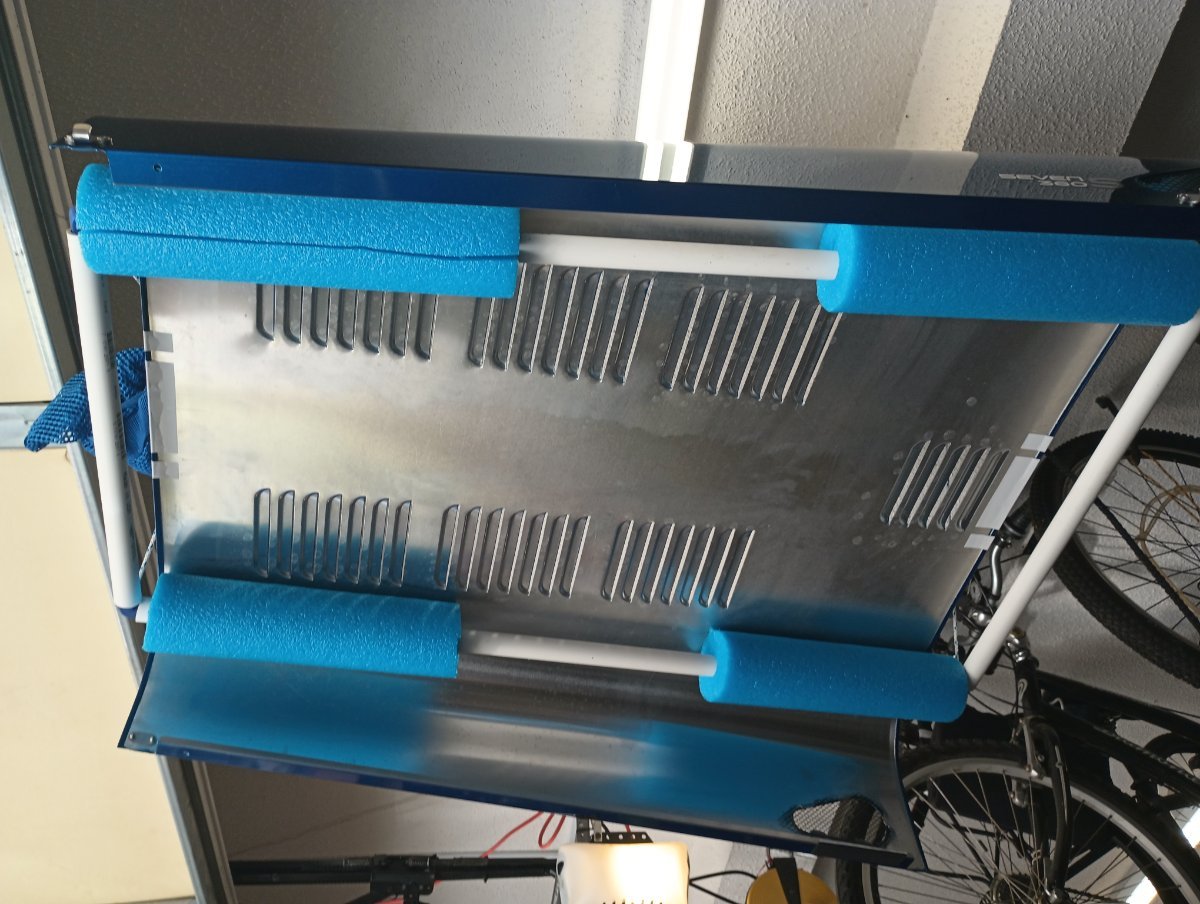
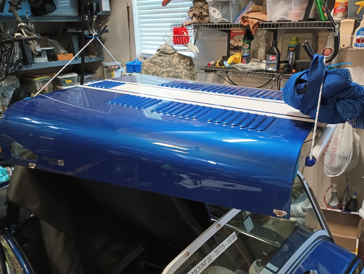
Thanks to all for sharing your ideas. I mocked up a frame with 10' of 3/4 PVC, a pool noodle, and some 3D printed elbows. I hung that from my existing kayak sling, which formerly held a top for a different car. This works great. I can mount the bonnet with the car in its spot, and it can live up and out of the way. But hopefully not for much longer.
-
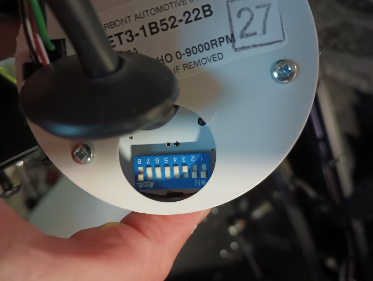
OK, some working through lunch... I set the switches to 0.5 PPR, on the logic that if my ECU is truly sending 1/4 pulses, I can just tell the tach that. Confirmed with ODBII, the tach now reads correctly with some caveats: - it's probably slightly less responsive, since it's getting 1/4 the data as before. Nothing I notice by blipping the throttle in the garage. - it bottoms out at 1100 RPM indicated. 800 actual (ECU) RPM -> 1100. 1200 actual RPM -> 1200. I assume this is a feature of the pulse-measuring algorithm, but doesn't otherwise seem to affect my usage. Per the book, 0.5PPR is 1-7 off (0 0 0 0 0 0 0 1). 8 stays on all the time.
-
referring to your previous post: https://usa7s.net/ips/topic/13527-tach-misreading-on-420r/#comment-124677 For future reference: the table for switch settings. 1+2+8 on (rest off) are the factory settings. Per the table, 1+2 is 2 pulses per revolution, which is "correct" for a 4-cyl / 4 cycle motor. Switch 8 is always "on". So I need to get it reflashed to make the tach work. Womp womp. To pull the tach: had to nip 2 zip ties under the dash to free up the cable a little. Gently pry the grommet loose, the switch is right under there.
-
The white-backed tach? I pulled the tach off the dash enough to see that it's mostly / appears to mostly be a sealed unit. Not too hard to pop the cover?
-
weekend update: - my front brake system + clutch bled normally, rears are (were) doing something weird. As above I used 15# on the power bleeder and it shoved through whatever bubble was in there. - the temp sender (submarine) appears to read high, like 110 indicated == 100 (ish) actual. That sender is only connected to the gauge, the ECU kicks in the fan at what appears to be the right time. - wet sump oil dipstick may be high, checking on it. 2015 and v2 Ikea manual differ. My engine came with the dipstick tube mounted high (Ikea manual), the 2015 shows a lower mount. 5 qts of oil and it's building the right pressure, so this feels like a dipstick issue and not something else. Have not tried to peer into the pan or otherwise, objectively measure the oil level. - tach is reading 1/4. Still figuring this out, I sincerely hope I don't have to mail the ECU in for a reflash. - now that I have power I can play with the dash. I feel like there are ~ 2x as many switches as I need, and not enough gauges. For starting, the book (new Ikea manual) has a fair series of steps. Mostly: build oil pressure before firing, and use the inertial switch/sensor to stop the fuel pump. Once pressure is up it just kinda works. Couple nagging coolant leaks; nothing major, just super annoying.
-
for the record: Motive 1100 and 1109 both fit the Ate reservoir which came with my ~2021 build. The 1100 part is plastic one-piece, the 1109 is an aluminium with swivel. Apparently (per Motive) that's the difference -- that and $12. My front brakes bled fine, the rears did not -- but 15# with the power bleeder pushed through whatever lock was in there.
-
OK, I think that makes sense; you would effectively be piggybacking on the 10A fuse for that socket, so you wouldn't need an additional inline fuse. I was thinking of running a fatter fuse for a Stiebel horn (~18A, it claims), have been trying to confirm that I won't nuke something else inline. I assume the wiring is pretty much battery -> fuse panel -> horn fuse -> button -> horn, without any other electromechanical stuff in the way. Alternative path (for like MCs and stuff where you aren't sure it can bear the load): horn wire -> relay, and run ~20A direct from battery to relay. Still get the horn function but don't potentially overload the button or whatever else might be inline. Downside is yet another fuse required for that 20A run, plus the additional wiring and the relay hanging out somewhere.
-
You wouldn't run that straight off the battery?
-
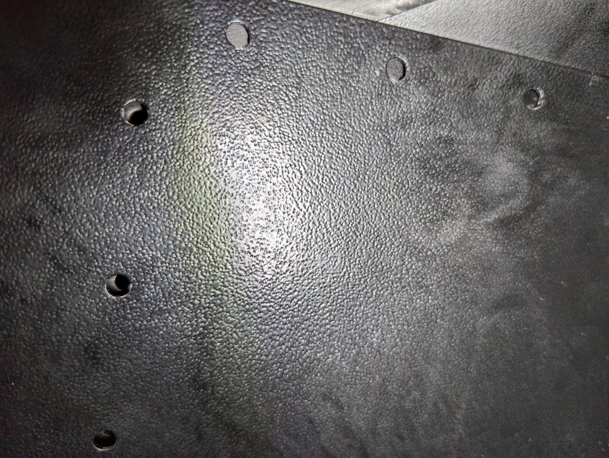
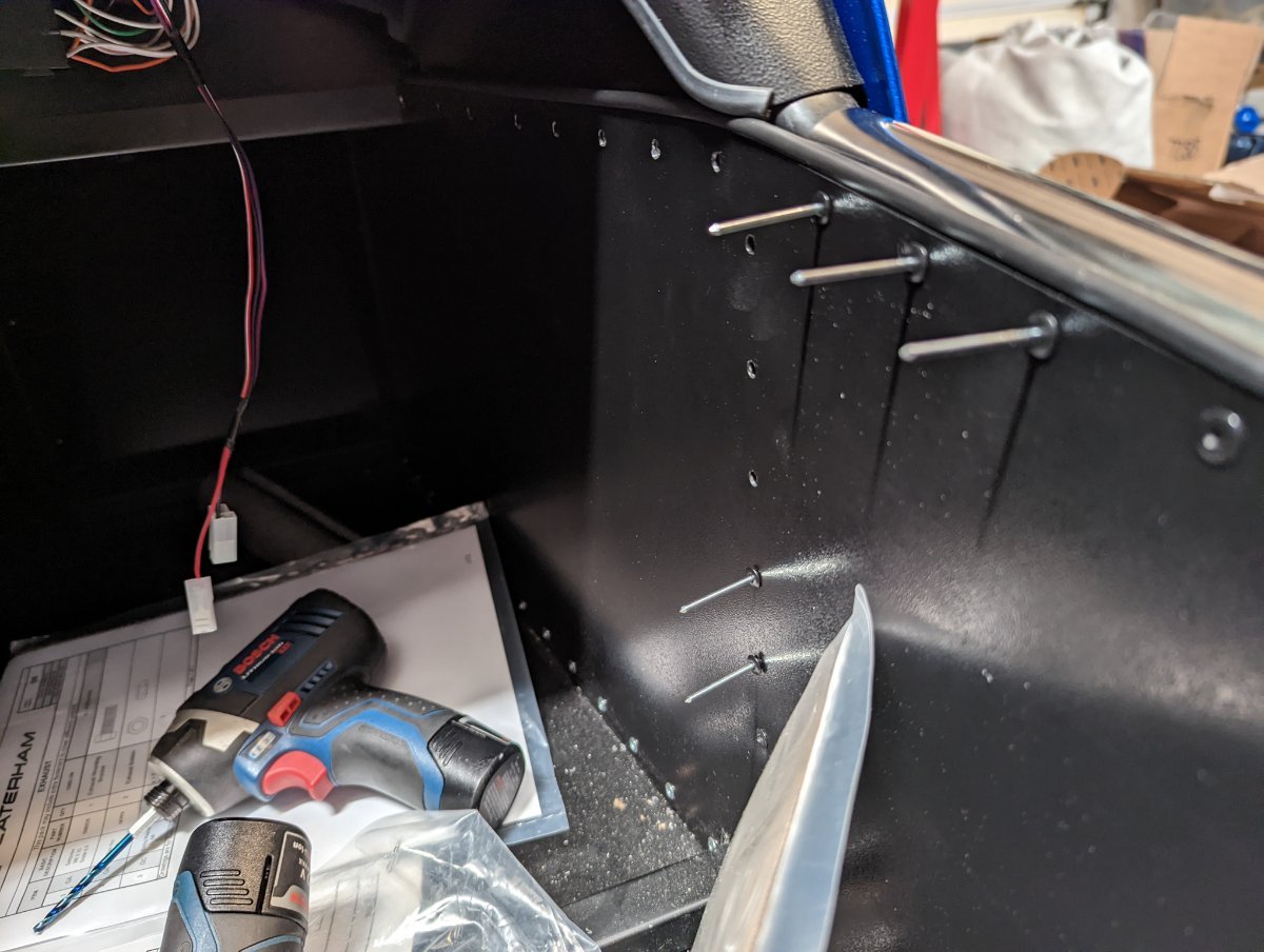
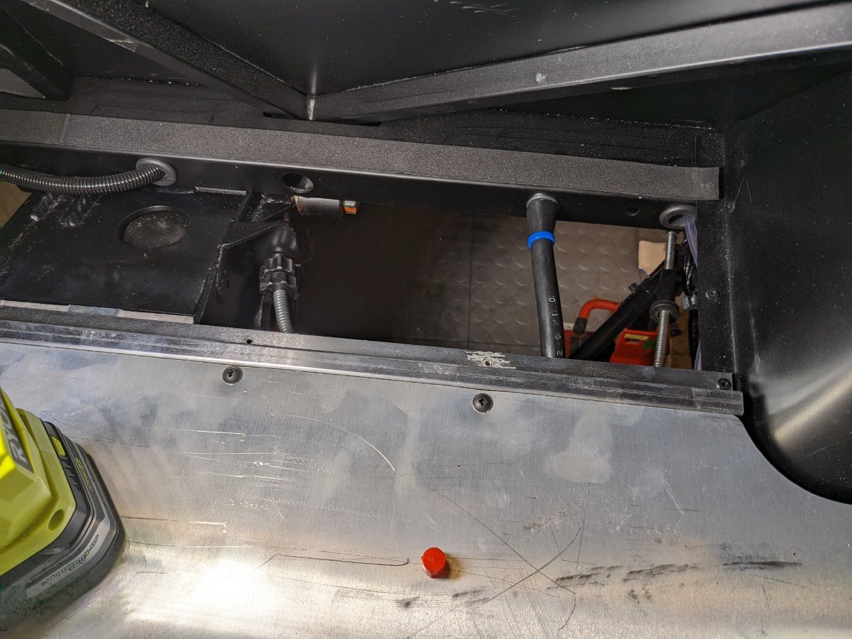
Quick question: the "fuse box cover" goes on LHS in the book, but is it really meant to be RHS on our LHD cars? My fuse panel is on the RHS. The cover is being shipped over from England, so I haven't actually seen it yet. A departure from the Ikea book (page 151), the knee panels under the dash. Book says to drill the 7 holes for the knee panel (do not), and acts like the outer 3 holes are pre-drilled (they are not). The 7 are OK, the last 3 needed to be drilled out. The 2015 book / page 148 matches my experience -- drill out the sill panel, the rest are ready to go. Some shots of the LHS knee panel under the dash. The hole pitch looks perfect from the outside, but the elbow in the panel interferes under the dash which prevents the whole thing from lining up correctly. The OBDII port lines up pretty good (hard to tell from the weird angle). I think these are offset by about 1/4 - 1/2", not quite sure. Both sides are like this. They seem to fit up nicely when tucked under the dash, between the plastic dash cover and the metal frame, apart from the holes not aligning. I haven't yet decided what to do about this, options are either "trim the edge of the knee panel" or "drill new rivet holes in the knee panel." I'm holding off till the last minute before I decide what to cut. Finally, note that there are at least 3 holes per side that have to be drilled out if you have sill protectors. To fit the knee panels, the side interior skin is left 3 rivets short from the dash toward the back along the sill, plus 6 straight down. The skin/interior panel has holes drilled in them, but the rubber insulation bead is intact AND the rollover polished steel arm / sill cover is not drilled out. I broke a titanium metal bit going in there, so I invested $6 in a stronger 5/32 HSS impact bit, which was a lot easier. And, naturally, the sequence of events is important: these 9 rivets should go in LAST, after the knee panels are in place. Leaving them all out gives room for the interior panel to give a little while you're fitting the knee panel.
-
Bonnet storage during maintenance?
Austin David replied to Austin David's topic in General Sevens Discussion
These are amazing ideas, thanks everyone for sharing! KnifeySpoony: next time I'm in the Bay Area I'll holler. From what I can see, you have the king of speed holes... -
The welds generally look good and everything appears true so far. Some oddities (like the RHS ground point) have me confused. There's a covered hole on the LHS in about the right spot, but the kit also came with an extra ground cable. Can't tell if they meant to move that to RHS because my LHD pedal box is in the way, or a series of offsetting errors, or what. Not documented, I also ended up with an RHD clutch hose. No idea why. The proper hose was fit to the bellhousing with the engine parts, which came indirect. I assume someone just pulled the wrong part and threw it in a box. Also if anyone needs an RHD clutch hose....
-
Any good ideas where to store the bonnet during maintenance? It's kinda big and floppy and painted, so I don't really want to lay it on the ground and can't easily prop it up. I have a ceiling-mounted sling that might work (used for the top of a previous toy car) but not sure how well it would hang. Anyone got any good ideas?
-
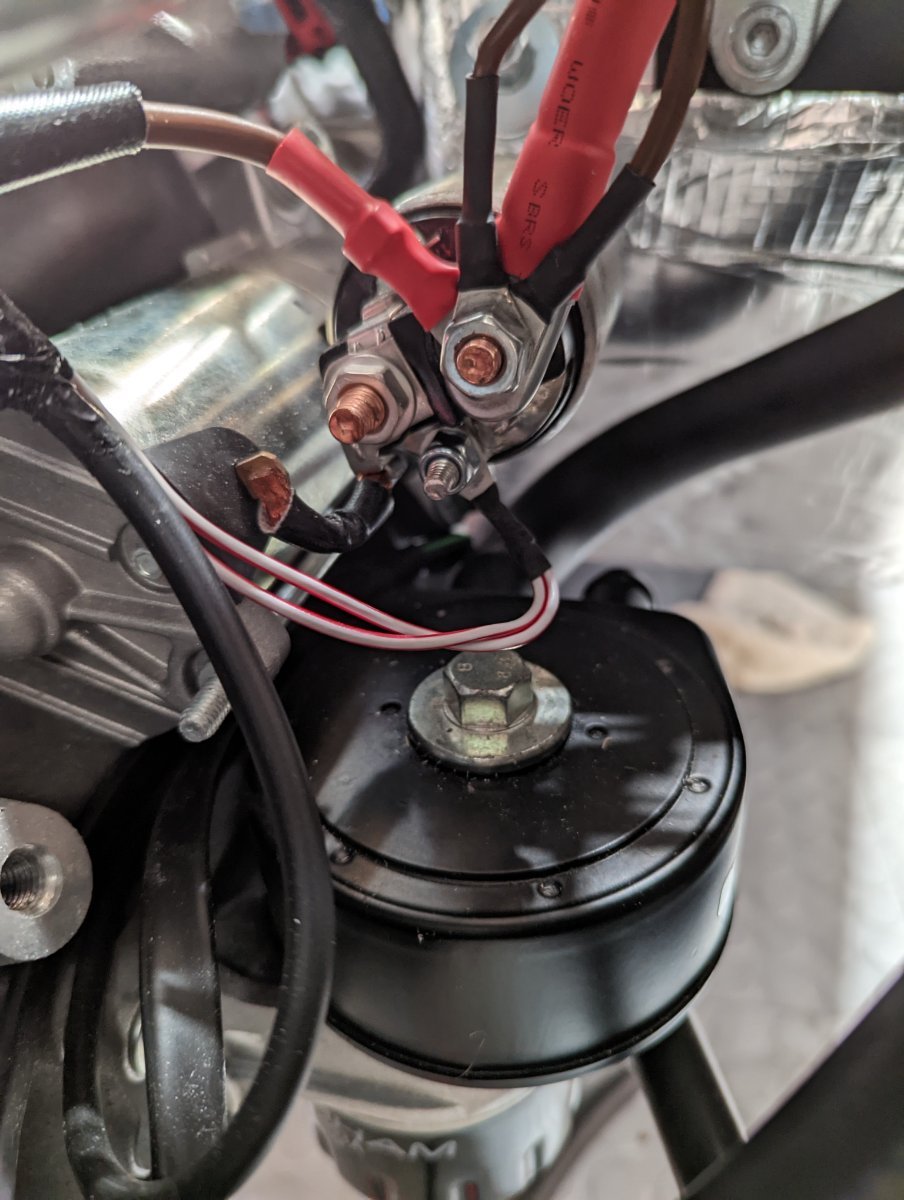
Starter wiring: as noted, I sourced the battery -> starter cable locally. The terminal is pretty fat, which ate up a lot of space on the screw. The nut does seat on all threads, but there's not room for an extra washer. I will tie off the red/white wire to be sure it doesn't lay on that modine nut. The rest are off the column and generally tied up along the loom running above the footwell. They all come from above (and don't leave a lot of slack). They need to splay out enough to let all the rings seat (and not bind on the crimps), but obviously there's not a ton of room to spread out. Also that locally-sourced starter cable had a BIG terminal and needed to be oriented mostly-vertical, to fit behind the insulation on that solenoid. Not obvious here, but that aims it right at the steering column, so it immediately makes an outboard jog to the frame tube where it routes with the rest of the cabling.
-
more pics / catching up: the "Submarine". My loom left very short leads for the two temp sensor wires, so I made a set of extensions: male spade on one end, and the other (red) female spade, or (black) ring terminal. Here's a shot of the final submarine. I used an "LS Heater Bypass" which apparently is super common and easy to get in your favorite color or material -- 3/4 to 5/8 in a 180* U Hard to see in the shot but it clears the firewall just fine. The other end of the sub is one of my straight 5/8 "Caterham" fancy hoses, which makes the run up to the valve and needed only a slight trim.
-
Sequence update: - the starter is sort of in the middle of everything. Hook that up fairly early. The Ikea 2.x manual more closely matches my build; brown wires + alternator + battery on the starter solenoid(?) terminal, the red/white ECU control to the lower terminal. There is a 3rd, not shown in the book, which is soldered to the starter motor. - the lower modine is sort of blocked by everything else. The inside (toward centerline) port can take a 90* 3/4" tube up to the tee with plenty of room to route around everything and up along the skin. The outside port gets another 90* 3/4, which splices down to 5/8. The 5/8 snakes from the heater, around (probably under / TBD) the upper cooling hose, between the starter and the steering column, then to that junction. - the upper cooling hose to radiator needs some trimming. I got the older EPDM host, it's SUPER THICK. It runs under the "plenum" and inside the dipstick (wet sump). It blocks most of the access to the plenum bolts, esp the furthest-aft. - set up the lower / modine tubes, rest the upper radiator hose on the path to the radiator, position the dipstick, loosely fit the plenum, RE position the cooling hose and get the 5 plenum bolts in place, then it looks like there's room to fit and snug up the radiator hose. It's all super tight in there and the heater-to-modine will want to rub on either the steering column or starter or maybe both. I will add some sort of protection, probably a nylon jacket on the steering column and use that to secure the hose off the starter. The knee panels under the dash: I've read that the holes don't line up sometimes. My holes are spaced perfectly (at least on RHS), but the panel itself won't fit under the dash plastic piece far enough to get the holes in line. I would either trim the back-facing edge of the panel to shorten it, or tap new holes in the lower edge. I'm inclined to the latter because it's easier to get right, and will be covered by the interior.
-
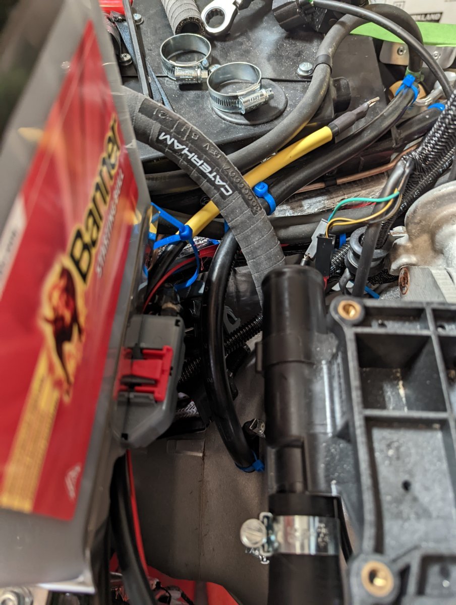
Here's a pre-engine photo which shows the older-style "2 brown wires", and also my RHS ground point by the battery. Also this shows I think the first time I had the airbox installed (I'm on #3 now)
-
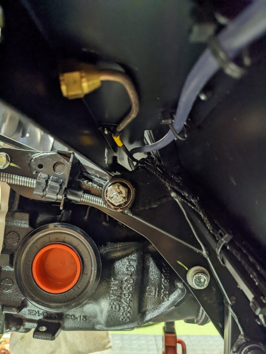
One other build oddity: my rear brake hardline didn't align with a hole in the aluminium support. It sort of matches the Ikea manual, which shows the hardline penetration, a lightening hole, then the washer passthrough. On my car there was a hardline NOT aligned with a hole, then the lightening hole. So I had to drill out a new passhthrough fitting. It was fun, as there's basically zero space. To do it again I'd find a right angle adapter.
-
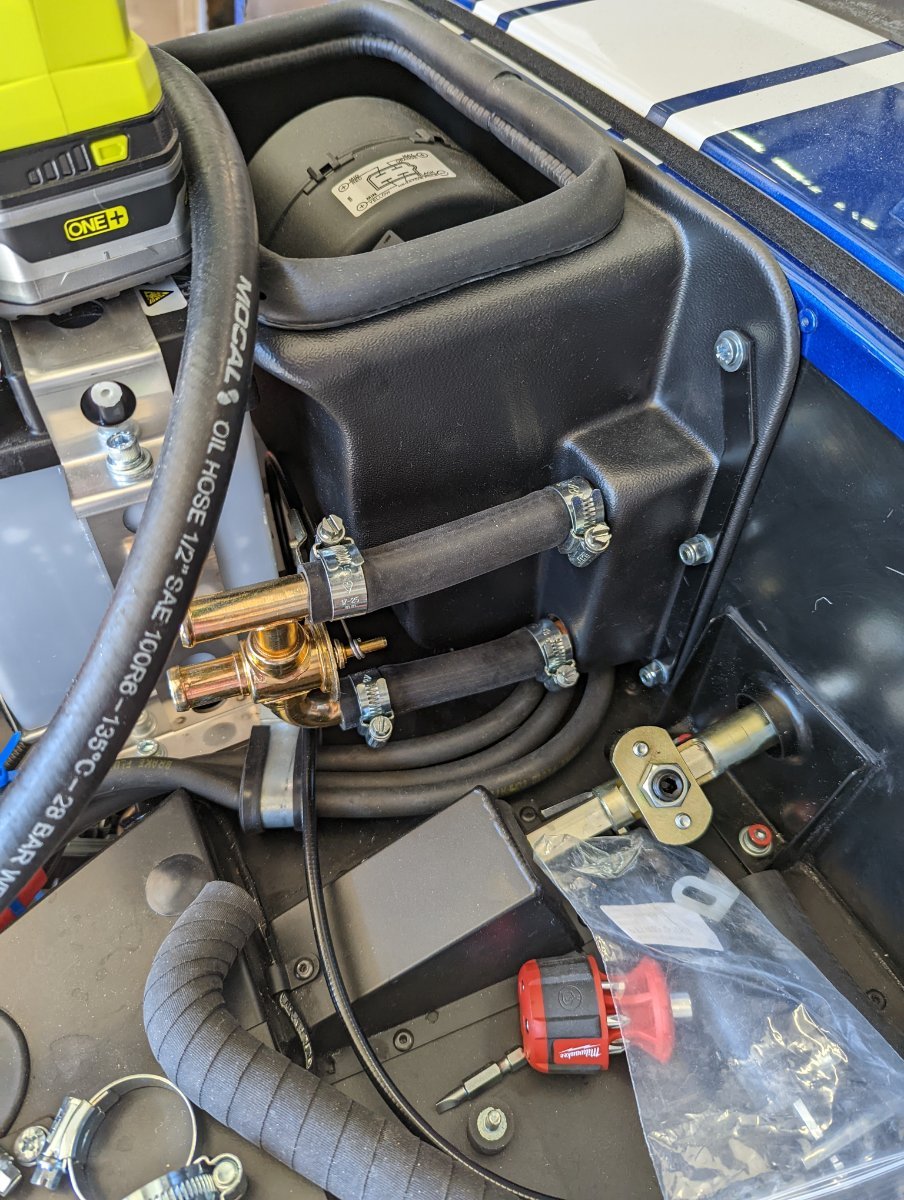
More photos: the valve arrangement for the heater. My switch/pull is on the LHS, I am planning to route it under the airbox, behind the battery, and doubled over for the valve. It seems to fit correctly and with a tolerable bend radius. The 5/8 tube pictured was acquired locally. I may later replace it with the (much nicer) Caterham tubes, once I sort out what-goes-where.
-
ha, my bad. Here's a photo of my missing plumbing. The kit came with 4 very nice, branded 5/8" tubes. Relatively short. No J for the submarine (5/8) and no 3/4 material at all. There was some bulk 1/2 and 5/16-- the 1/2 was used to protect the rear brake hose, the 5/16 is perfect for the clutch hose, the rest for the smaller line on the overflow tank. From talking with Josh (therefore indirectly with Caterham) it might be that they intend to splice some of this together, and mostly use the two Ls for the modines. I'm not 100% sold, in that the modines are a full 1/8" larger...