copy.jpg.dd4bdbb41ccb3ea8a585d1ad217ef61b.jpg)
.jpg.da03509438cc84820b8cf5d64db570ab.jpg)
Austin David
-
Posts
416 -
Joined
-
Last visited
Content Type
Profiles
Forums
Store
Articles
Gallery
Events
Library
Everything posted by Austin David
-
I feel like you got a pretty solid deal on that ride. Enjoy the h*ck out of it!
-
The torque spec is in the arm of a skilled mechanic.
-
Ditto. I assume it was painted (coated?) to match the frame
-
.thumb.jpg.885191d302e6c3704c848a8f5ac3a612.jpg)
Photo of your car you took today
Austin David replied to Xhilr8n's topic in General Sevens Discussion
mailin stuff
-
this
-
Congrats! That's a pretty car. Personally I'd put an aeroscreen near the front of the list, esp for day trips. Smaller wheels and stuff are great but until you get to know the car you may not know the difference. For me I'd prioritize the first trip, then work from there.
-
The Regular Summary of Classified Ads of Se7ens Found For Sale
Austin David replied to Croc's topic in Cars For Sale
Congrats! You've got a lot of room to clean it up and still not* be horribly "underwater". Holler when you get it sorted, I'd love to get a group of Caroliners together for a lil run -
The Regular Summary of Classified Ads of Se7ens Found For Sale
Austin David replied to Croc's topic in Cars For Sale
Start or continue a build thread please! I plan to drive mine until I can prove it's open. Its been clunky from day 1 -
The Regular Summary of Classified Ads of Se7ens Found For Sale
Austin David replied to Croc's topic in Cars For Sale
I'm at 17k and "fairly sensible", my 2021 diff (M1 housing + titan guts) seems fine if noisy. I have read that the expected life is a lot lower, but here we are. I'm not looking forward to fishing it back out when it's time to replace the internals tho -
The Regular Summary of Classified Ads of Se7ens Found For Sale
Austin David replied to Croc's topic in Cars For Sale
HAHAHA I can't use a GoPro on my roll bar, the audio is dominated by the clunking. That LSD is about 6" away from your ear and very firmly attached to a drum. It's supposed to be loud. "clutch funny" doesn't sound right, but the hydraulics is simple. FWIW "needs several thousand dollars" is probably always true. Welcome to the show. My boy-math would include something about the utility of having one to play with while you keep looking, and the fact that if you were able to buy it, you can also sell it. It's not an "investment" but it's probably a pretty solid rental. Tires, "maintenance" etc are all true no matter what you get. The fact that it needs different tires would also be true if it had 10-year-old ZZRs. -
Prisoner Edition Caterham for sale - $39,500
Austin David replied to Columbiacaterham's topic in Cars For Sale
I've seen another of these here in Charleston! The first seven I'd seen. The color combo is pretty cool in person. I love that you have retractable seatbelts -- a better choice for a road car IMO -
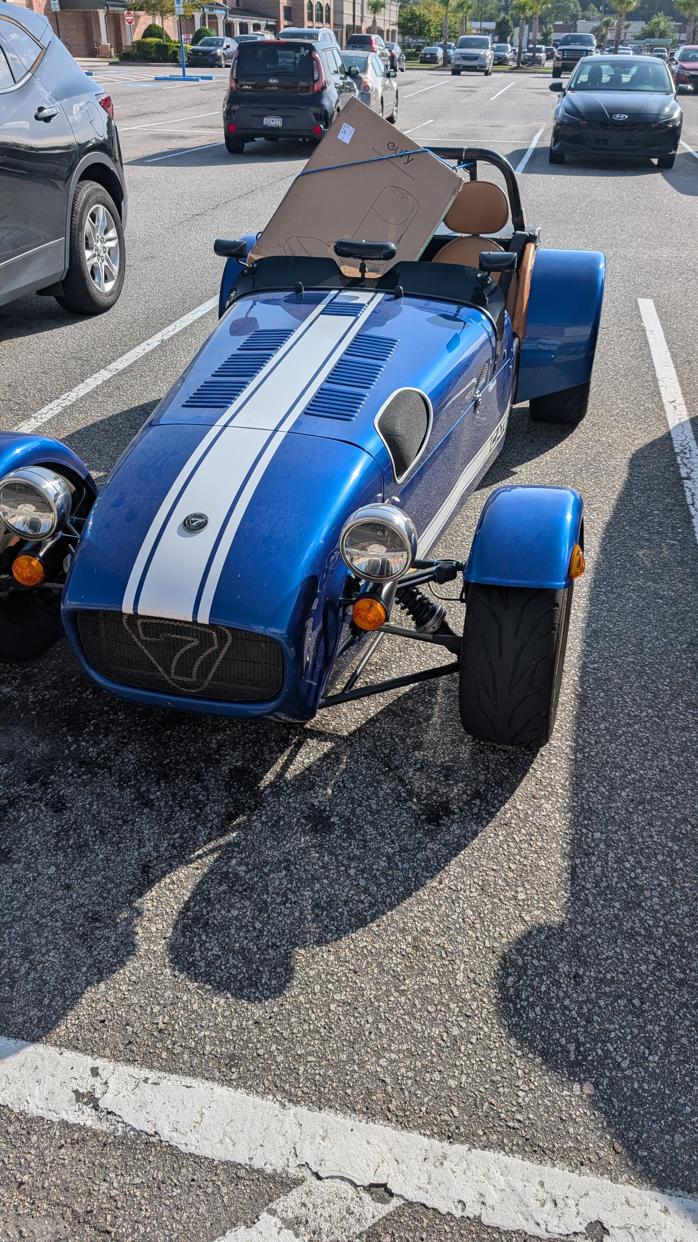
Photo of your car you took today
Austin David replied to Xhilr8n's topic in General Sevens Discussion
finally figured out how to park up top; the clearance is a challenge with the crossbracing. Likely coming back down tomorrow, had to bring out a Miata for some suspension work.
-
quick plug for route7.austindavid.com which can more-easily make routes and export to Beeline ... also that's genius. I never even looked at that stem. but I like mine close to the line-of-sight, just above my right hand.
-
I interpreted it as "stopping point".
-
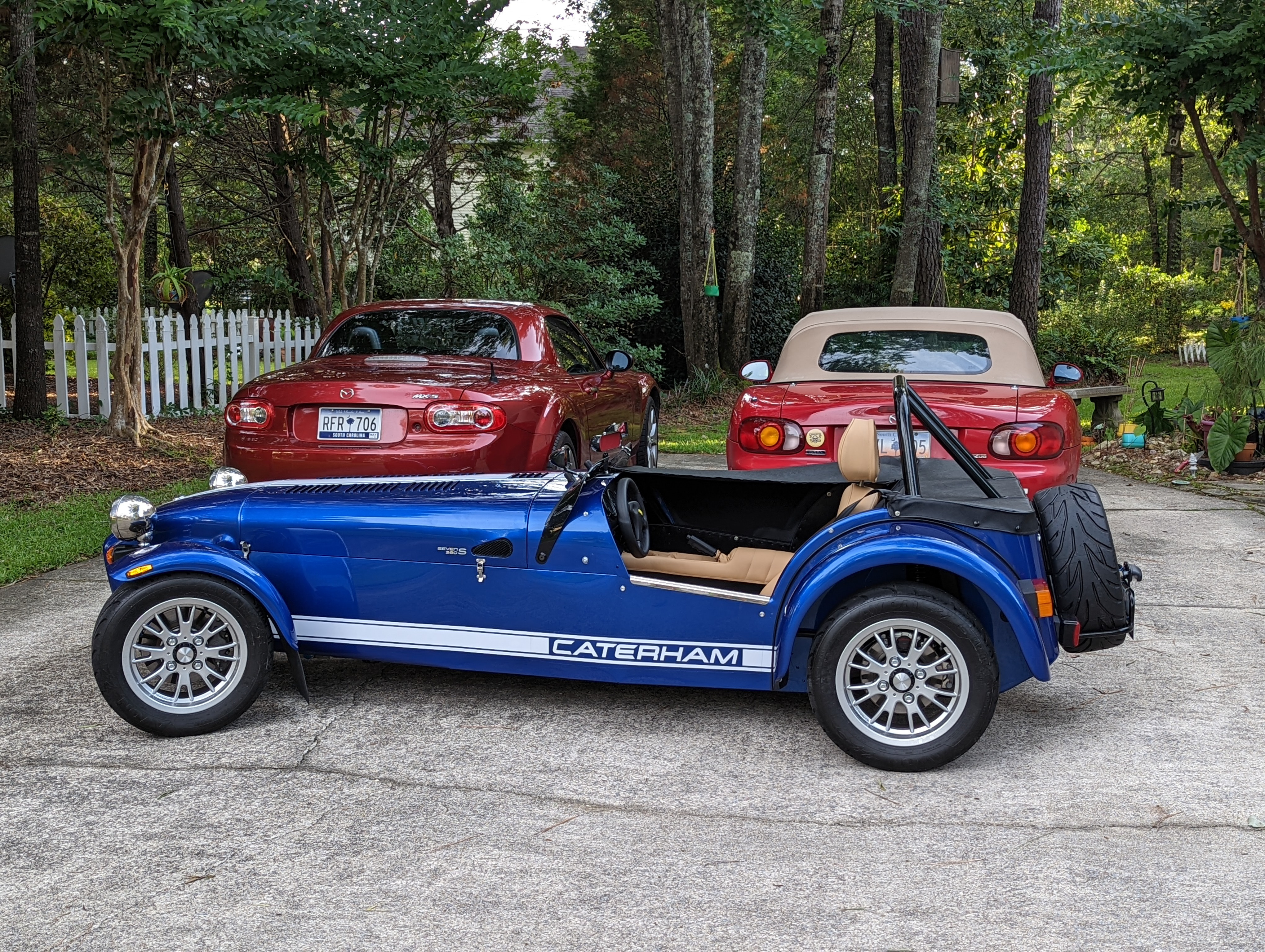
Photo of your car you took today
Austin David replied to Xhilr8n's topic in General Sevens Discussion
also a backup miata
-
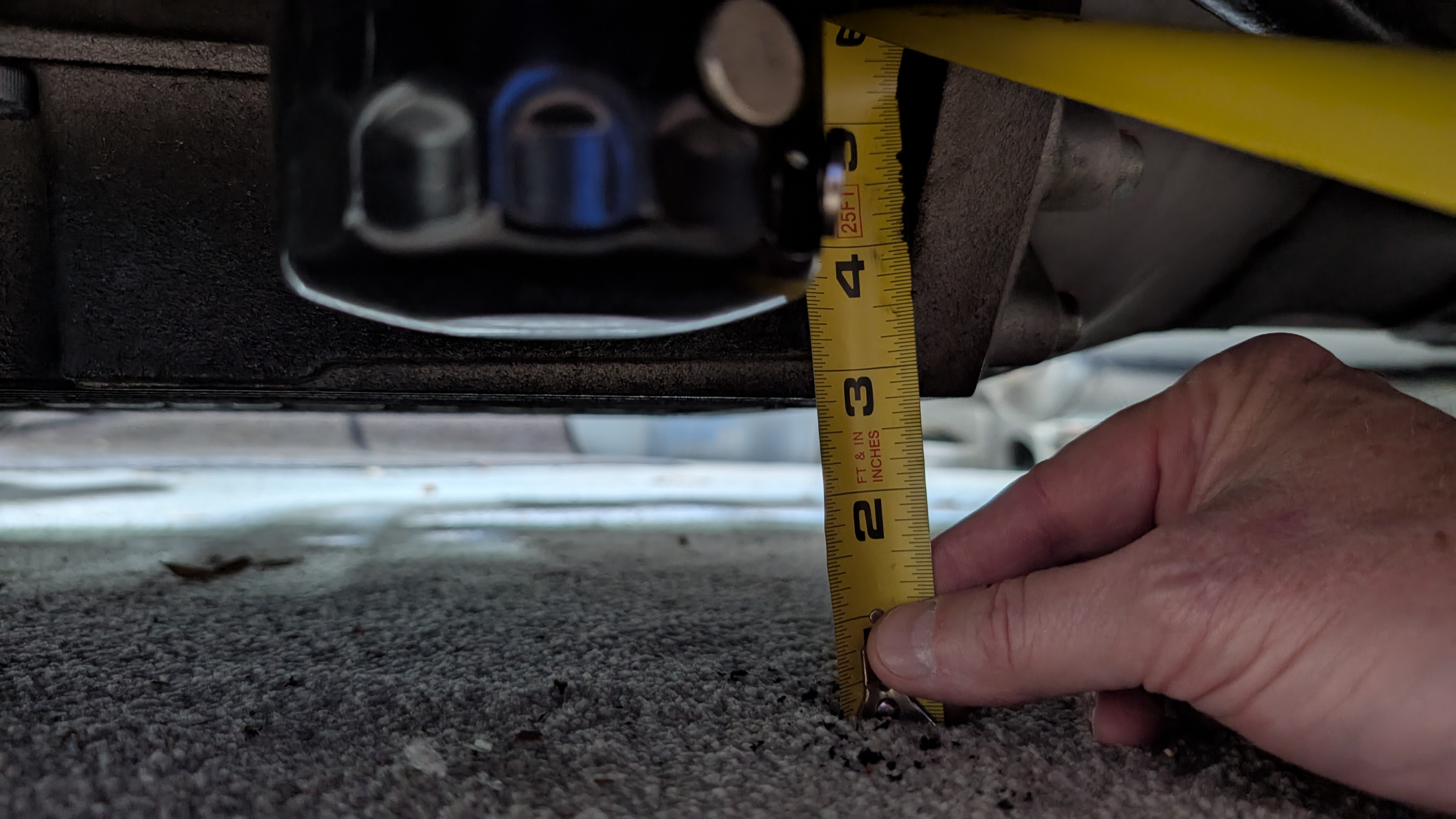
< 3". this is the back of the pan, which afaik is the lower part. And further behind the wheels, so more likely to caress the odd speed bump. Squirrels and such will catch the front, but for roadkill I worry more about the nosecone. Note that I once caught a bird on the left cycle wing; that was gross. Like hitting a waterballoon full of ketchup. Note also that the bell housing is not much higher than the pan; the bigger difference is that scraping the housing is less likely to drain out all your oil, but you will still scrape.
-
Photo of your car you took today
Austin David replied to Xhilr8n's topic in General Sevens Discussion
not pictured: picture -
So, tell us a little about yourselves
Austin David replied to slngsht's topic in General Sevens Discussion
ah, this is a great place to start. there are a jillion resources and examples of people like me, even more clueless. As weird as they are, these cars are relatively simple -
So, tell us a little about yourselves
Austin David replied to slngsht's topic in General Sevens Discussion
Josh is a great guy, you're in good hands. The wait is PAINFUL tho -- but at least you're not getting the COVID edition -
FWIW my pan has touched a few things gently, I'm still on the first one. I've learned how to better avoid high spots, like the optimal path through a few parking lots to avoid speedbumps altogether. Do you also have to adjust ride height or rake after swapping to taller wheels? I assume a speedo recal is required too
-
honestly, full syn 5-50 isn't that hard to source, and is not too expensive either. Maybe do that first, or "do it anyway"? I get mine in bulk from O'Reilly, Mobil-1 with free shipping sometimes. Ends up about $10/qt, which is more than what I put in cars I don't care about, but not a lot more.
-
I've been tricking my wife and sister into making durags. So far I've only lost one of the good ones, and I e earlier store bought. Both at 70+ while passing, I'm an aeroscreen user. Between a durag and gaiter I can keep most my skin covered. But this gets to the earflaps problem, where air buffering the flaps (or gaiter) transmits directly
-
Photo of your car you took today
Austin David replied to Xhilr8n's topic in General Sevens Discussion
And a separate tutorial for managing ones wife -
Photo of your car you took today
Austin David replied to Xhilr8n's topic in General Sevens Discussion
Curviest road we have is I-526 -
@JohnCh and I have been chatting a little about a "find along route" style feature. I've got a proposal I'd like to share, in case anyone has any thoughts. I've added followup below for why "find along route" is not easy. (note the following is AI-generated, but with a lot of guidance) Here's the experience from the rider's side — what they see and do, start to finish. The setup You're in the route editor, building a ride. The map fills most of the screen; your waypoints sit on it as numbered, draggable pins. In one corner of the map there's a single small icon — a pin+ button. That's the entire footprint when you're not using it. No panel, no sidebar row, nothing competing for space. Finding stuff You pan and zoom the map to frame a stretch you care about — say a section of road where you'll want a coffee stop. Nothing happens as you scroll — no searches fire, no spinner, no cost. The map is just a map until you ask it for something. You tap the pin+ icon. It expands in place into a short row of category chips: Fuel · Food · Coffee · View. Still nothing's been searched. You tap Coffee. Now one search fires, scoped to exactly what's framed on screen. A handful of results (~6) drop onto the map as a visually distinct pin layer — a different color/shape from your route waypoints and from the curated nearby-places pins, so it reads instantly as "candidates, not yet in your route." Alongside the pins, the control shows a compact list: each result's name, star rating, and rough distance from the center of your view. Importing one You tap a result — either its row in the list or its pin on the map. A small info card opens with the name, rating, and one primary button: "+ Add as waypoint." You tap it. The place becomes a new numbered waypoint in your route, instantly — the route re-routes through it, the new draggable pin appears, and that candidate pin disappears from the provisional layer (so you can't accidentally add it twice). The waypoint inherits the place's name as its label. Adding more, or backing out Want a fuel stop too? Tap another candidate → "+ Add." One tap each. Want different results? Tap another chip, or re-frame and search again — the old candidates clear and the new set drops in. Done exploring? Collapse the control (tap the icon). All the candidate pins vanish and the map returns to its clean baseline — just your route and that one small icon again. The feel of it The whole thing is invisible until you reach for it, and gone the moment you're done. It never searches on its own, never writes anything to your saved route until you explicitly add a waypoint, and never clutters the screen with results you didn't ask for. The motion is: frame → tap category → tap result → it's a stop. Three taps to the first one, one tap for each after. A couple of honest edge cases If the map hasn't settled (no bounds yet), tapping a chip just says "pan the map first" instead of firing a useless search. If your route's already at the waypoint cap, the "+ Add" button shows disabled with a "route full" note rather than silently failing. "View" maps to Google's tourist_attraction category, which is a bit coarse — it can surface a museum where you wanted a scenic pullout. That's a known imprecision, called out as an open decision (accept it, or curate the category list). ----- Why "find along route" is hard: - the various Google APIs are not free, but there is a $200/mo credit. "search for a place" is the single most expensive request - "Search for a place" can return only 60 things at at time. For a long route "all the places within a mile of the planned path" is a lot more than 60 - there is no API for "be smart about what you find". You can search for "gas stations" but only in a radius; finding "all the gas stations along a route" is a lot of searches - Google Maps has some magic and their own free-to-use stuff built in, and it works pretty well: "navigate A->B" + "find gas along the route" is a lot smarter than what is publicly available to a service like route 7. - I *have* implemented 'stuff close to a waypoint' -- it's a lot easier to use. Give it a shot, tell me what you think. I use it by dropping a pin near where I think there is stuff (ie a town), then search for fuel or whatever, review the results. It's not "anywhere along route", but it is straightforward to use. As editor you can trim results (hiding mcdonald's or sus gas stops, for instance). The remaining hits show up alongside your chosen waypoint. There's discussion about a "make this a waypoint" feature, not yet added.