
11Budlite
-
Posts
2,266 -
Joined
Content Type
Profiles
Forums
Store
Articles
Gallery
Events
Library
Everything posted by 11Budlite
-

General Zetec powered Caterhams/7's discussion
11Budlite replied to Vovchandr's topic in General Tech
There's a pretty good write-up of one owners conversion to a Zetec on this site: http://my.voyager.net/~quadrant19/XF-to-Zetec.html I've seen this car in person and went for a ride with the owner at the TOTD and it was done very well. -
It's been a long time since I messed with carbs. I never worked on a Mikuni, but did have a Weber DCOE on a 1275 Spridget motor that worked pretty well. Was anything changed during the rebuild, idle jet, etc, and was it doing something similar before the rebuild? Have you adjusted the idle mixture? Maybe it has a vacuum leak, are you using the soft mount setup between the carb and intake manifold? Is this on a Ford Kent?
-
Welcome Ctcat, I have a friend with a Caterham that's not very handy and I will help him with some of his simple jobs when I have the time. Caterham's, especially a SuperSprint 1700 like his, are pretty simple and easy to work on. He did have to have some chassis repair done and brought it to GMT Racing in Newtown and was happy with the results. It wasn't cheap but they are very well regarded. What model Caterham did you get, and what type of work do you think you'll want done?
-
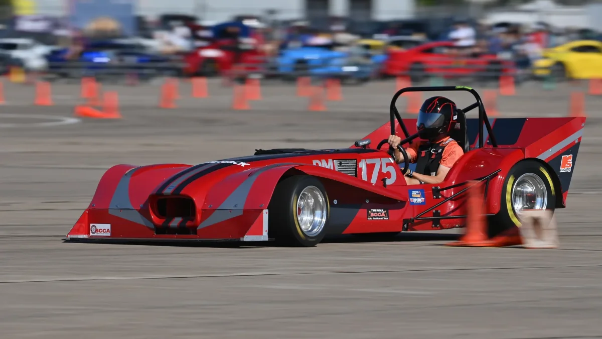
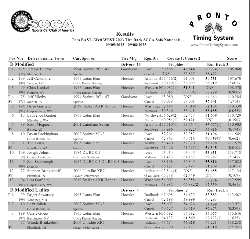
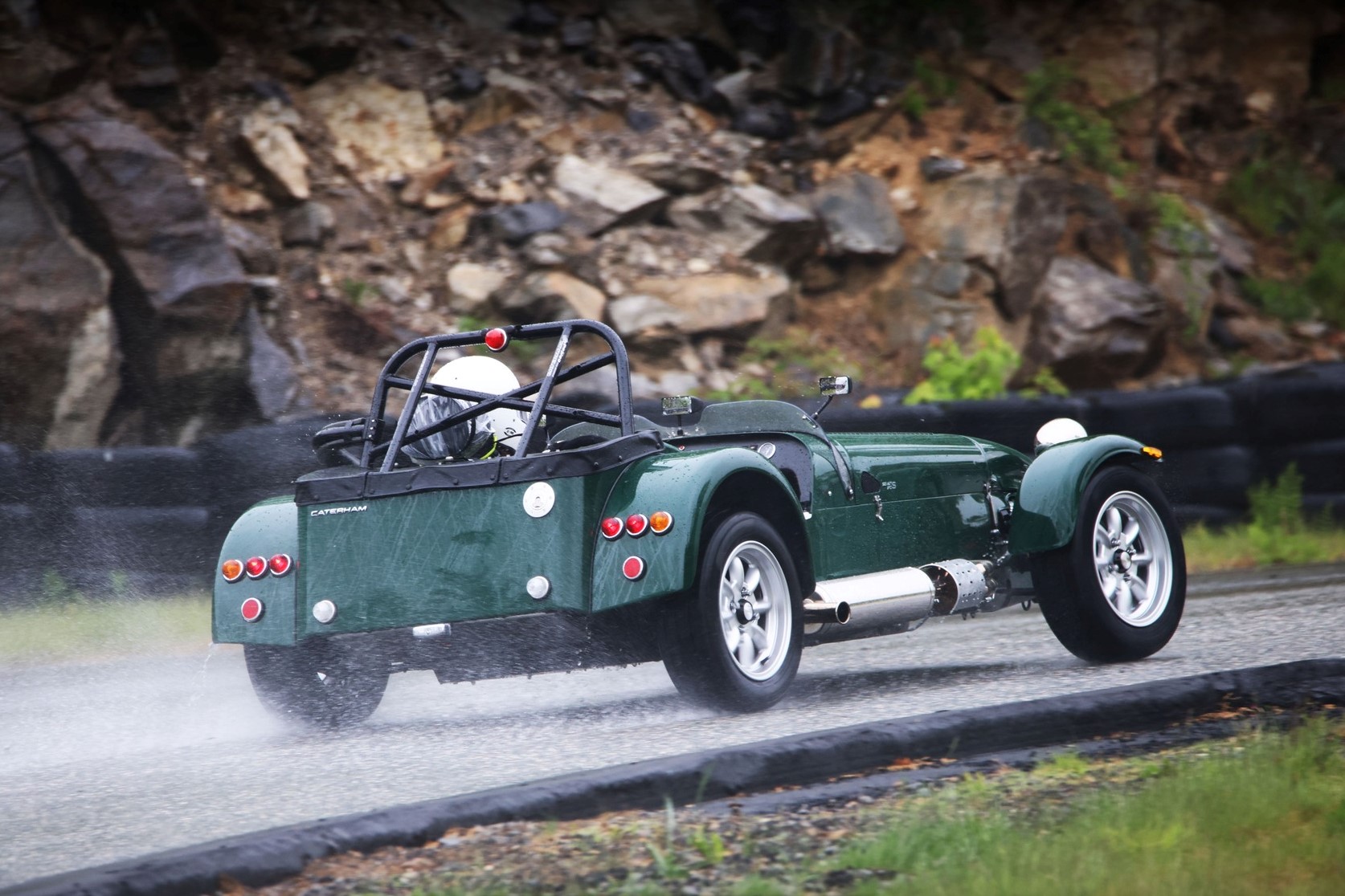
I have no experience with autocross, but I agree with what's been said previously. Looking at the results from last year, it looks like an Ultralite would be a good starting point to build a competitive D-mod car. I think you'd have to modify it to the limit of the rules, and then develop the suspension, drivetrain, and aero to gain every advantage of the platform. It should be a fun endeavor. Here's a photo of what I believe is last year's winner.

-
That seems to match up a lot better, thanks MV8!
-
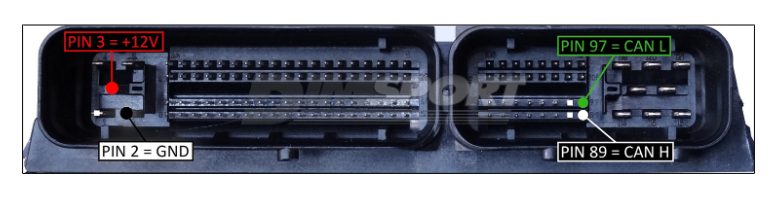
Other than my photo being upside down this seems to match. MBE 959 Caterham Pinout:
-
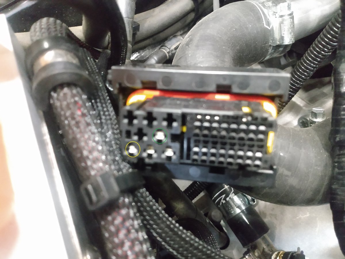
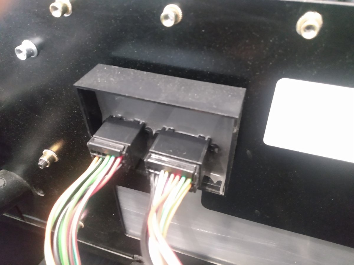
Here's a photo of the ECU pins. The big connector has pins 1-81, with the (5) big pins being numbered 1-5. The small connector has pins 82 -121, with the (8) big pins being numbered 114-121. "Does this fuse list align with what you have?" - I have 20 fuses but they don't match up with that diagram.
-
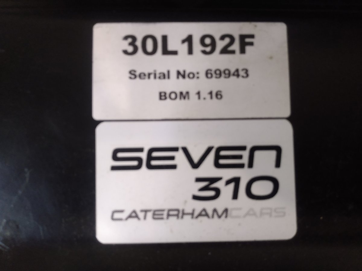
Thanks MV8. It's P/N 30L192 from a 2019 310S. I'm going to contact them this weekend, so hopefully they can respond early next week.
-
No heater for my car either! And also no MFRU or separate relays for the FP or cooling fan. I disconnected the (2) connecters at the ECU and saw a set of heavier pins, one on each connector. Checked for continuity between all of the pins and found (1) for the Y/G wire to the FP-Inertia switch and (1) for the B/G wire to the cooling fan. Both on the smaller connector on the drivers side of the ECU. FP circled in green in the photo below, and cooling fan circled in yellow. The wire colors are not visible at the connector without stripping back the sleeve/shielding.
-
Where's the MRFU? Still haven't located it.
-
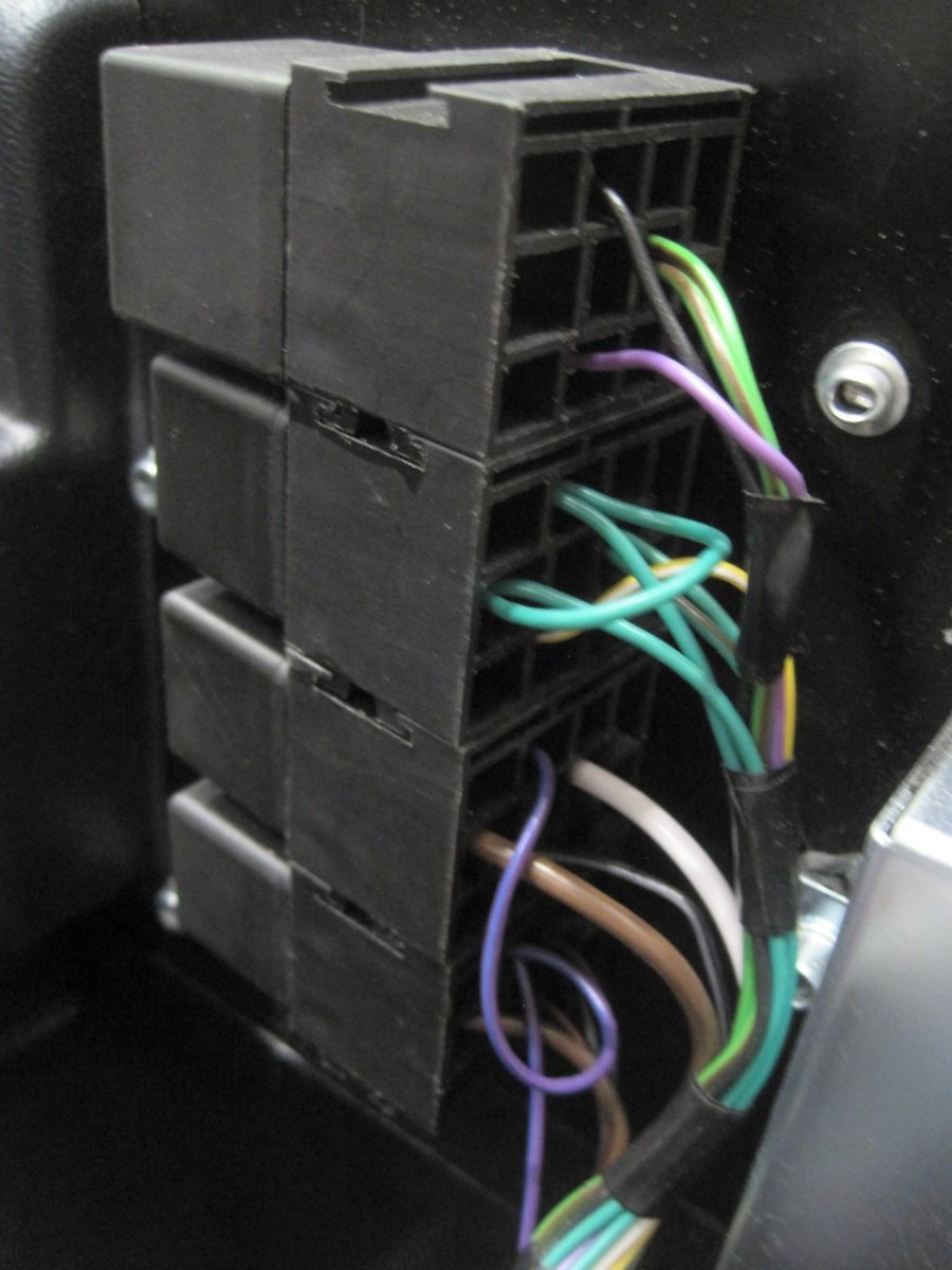
I had a chance to do a little more investigating early this morning. I was trying to identify all the relays and the wires that go to the different relay terminals. I have one relay that I'll call #4 that's located on the bottom of the (4) joined relay block on the right side of the passenger firewall. It has the following wires connected to the relay terminals: 86: P/U (Purple/Blue) 85: B/R (Black/Red) 30: N (Brown) 87: B (Black) This has me confused because the black wire at the 87 terminal has continuity to chassis ground. I always thought the 87 terminal was used to send power to the device you were trying to power up. Fuel pump, cooling fan, etc. Is there any situation where the 87 terminal would be hooked up to ground?
-
So I had a little time to do some investigating last night. I had the inertia switch and FP connected, but all the relays removed from their sockets. Connected the battery and the FP runs for a couple of seconds and then shuts off. That's with ALL the relays removed, at least the (6) I can find! The (2) Y/G wires from the inertia switch are wrapped together and travel to the maze of wiring under the ECU. I started unclipping the different harnesses and will see if I can trace where the other Y/G wire goes and maybe I can make some sense of this.
-
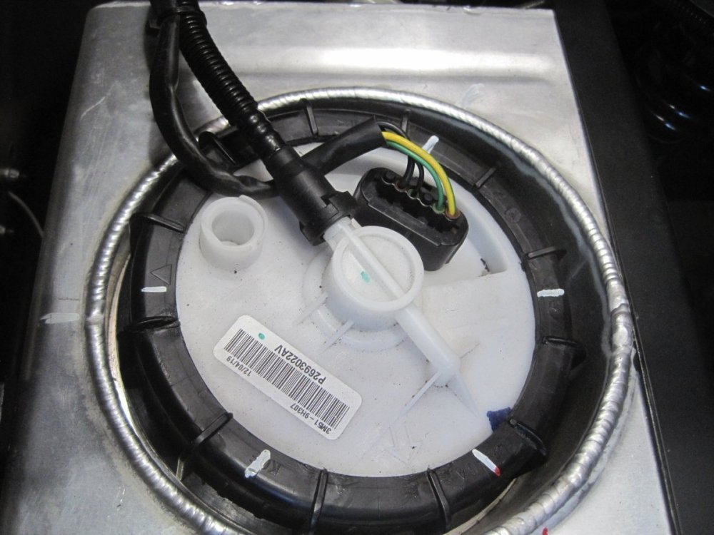
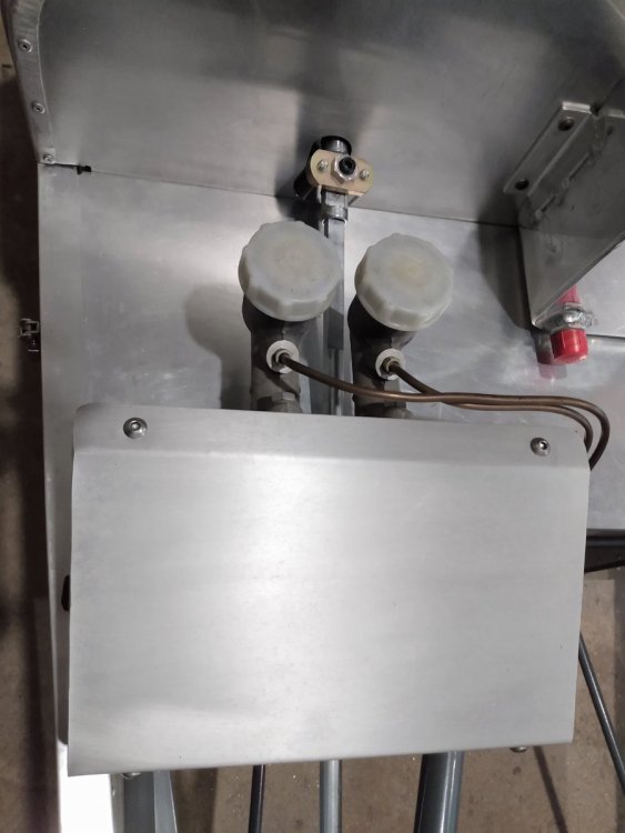
I guess I never mentioned why I'm trying to find the FP relay. The issue I'm trying to fix is the FP energizes whenever the battery is hooked up whether the ignition is on or not. It's getting the signal from the ECU because it builds pressure then shuts off like it would normally. The attached photo shows the connection at the FP. The Y/G wire at the FP does go to one side of the inertia switch. I checked for continuity between the other Y/G wire at the inertia switch and the relays and was unsuccessful. I'm probably going to have to unwrap some of the harness to see what I'm missing. I also found this Caterham with a similar issue: https://www.pistonheads.com/gassing/topic.asp?h=0&f=101&t=1895605&i=0 I know I've seen this connector in the dash wiring, so I'll be checking that diode as well. This is a distinct possibility. Didn't see a PWM controller on or near the FP/tank. With the help of JohnCh, we've noticed that the Sigma FPA is different than some of the Duratec FPA's which have the PWM controller on the side of the tank. There's a possibility that the controller is part of the FPA on the Sigma model because it's quite a bit more expensive. https://caterhamparts.co.uk/pumps-senders/3000-fuel-pump-sigma-and-duratec.html https://caterhamparts.co.uk/pumps-senders/5501-fuel-pump-seven-485-model.html I don't think this is related to my issue but it's always good to understand how things work. I also took the tunnel cover off and will check to see if that helps me locate any of the issues.
-
Thanks guys, I'll be checking those ideas out tomorrow.
-
The inertia switch has a Y/G wire going in and a Y/G wire coming out of it, no other wires. One of those wires goes to the fuel pump, I'm assuming the other one goes to the relay. The Sigma has only one line going to the fuel rail. I'm at work now and won't be able to do any more checks until tomorrow pm.
-
Thanks John. Unfortunately the Sigma layout is different than the Duratec. There are 4 relays on the firewall in front of the fuse box, and 2 others on the drivers side near the steering column. I posted photos of the 6 relays on a previous thread here: I'll check all the relays for continuity to the inertia switch even if they are different colored wires, and also check for a module on the left side of the tank. I don't recall seeing anything there when I had it apart before.
-
I wanted to give an update after my last track day on Saturday at Club Motorsports in NH. I ran 5 sessions for a total of 2.5 hrs on track. Spent more time at higher rpm than I did at Canaan, hitting redline in 3rd and 4th on a continual basis all day long. There were two black flags for a total of 10 minutes of lost track time. Checked the dip stick on the catch can and didn't notice anything during the day. Removed the can when I got back home and there was some oil in the bottom that after a full drain I measured to be 12.5ml which converts to .42 oz. There was no oil residue outside of the catch can or on the underside of the hood. It seems to be working much better than the stock Caterham plastic tank setup and it's been much easier to empty/clean up as well.
-
I'm trying to locate the fuel pump relay on my 2019 Caterham 310S. I'm assuming that it should have a heavier gauge Yellow/Green wire coming from the 87 terminal of the relay and it's switched by the ECU. The Y/G wire goes to the inertia switch on the firewall and then on to the fuel pump connector at the tank. I've looked at all 6 relays I can find on my car and don't see one with a Y/G wire coming out of it. Any ideas?
-
@CatManDo - I feel your pain. When I first started up my Caterham I couldn't figure out why the fuel gauge and temp gauge were giving weird readings or no readings at all. It turned out the signal wires were swapped (I think they were G/B and G/P), but thankfully I was able to figure it out without too much trouble. I'm presently going through some electrical issues with my car. I seem to have a fuel pump that is permanently on, as well as a draw on the battery (with the FP disconnected) that might be related to the fuel pump issue but haven't pinpointed it yet. The first time I took the scuttle off I couldn't believe how much wiring there is on the Caterham. I mean, it's supposed to be a simple car, right??? When I had my Birkin I spent probably a week rewiring everything under the dash. Some of that was wiring in the Emerald ECU I was using, but most of it was just the poor initial installation of the original build. I was hoping for a lot better with the Caterham, but the wiring/electrical/gauges and the lack of a decent wiring diagram/relay layout has been the only disappointment in my ownership so far. I ended up having to wire in a master disconnect switch until I can find the time to dive deeper into this issue. I'm going to start another topic as it relates to the fuel pump relay.
-
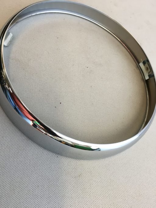
A couple suppliers I've used in the past: https://www.autoelectricsupplies.co.uk/c/lighting https://www.holden.co.uk/c/electrical/lighting/headlamps https://www.carbuilder.com/uk/headlamps?pagenumber=1&viewmode=grid&pagesize=20&orderby=0 Does it look anything like this one? This is from a Morgan flat radiator model from the 50's.
-
Can you take one apart and take a photo of the back side mounting arrangement? It could be similar to the chrome rings used on other British cars from the 60's. MG's, Triumph's, Austin-Healey's, etc.
-
collapsible steering column for 7 S2?
11Budlite replied to Timothy Keith-Lucas's topic in General Tech
I was able to update my S2 replica chassis to a later Caterham steering column to add just a bit of safety to the steering column. Probably the easiest option since it requires just the upper and lower columns and the clamping arrangement.
-
Congrats Charlie, your patience has been rewarded! Covering 550 miles on your first day is pretty impressive. Your car looks great!
-
Thanks MV8.
-
Does anyone know what this is? It has two connectors on it and mounts on the inside of the firewall above the heater opening.