
11Budlite
-
Posts
2,266 -
Joined
Content Type
Profiles
Forums
Store
Articles
Gallery
Events
Library
Everything posted by 11Budlite
-
Not taken today, but this is my latest photo.

-
I was thinking the same thing. Doesn't look like your typical tonneau that covers the driver and passenger seats. TR3, Morgan? Can you contact the seller?
-

Dedicated 7 track pictures thread. Post yours.
11Budlite replied to Vovchandr's topic in General Sevens Discussion
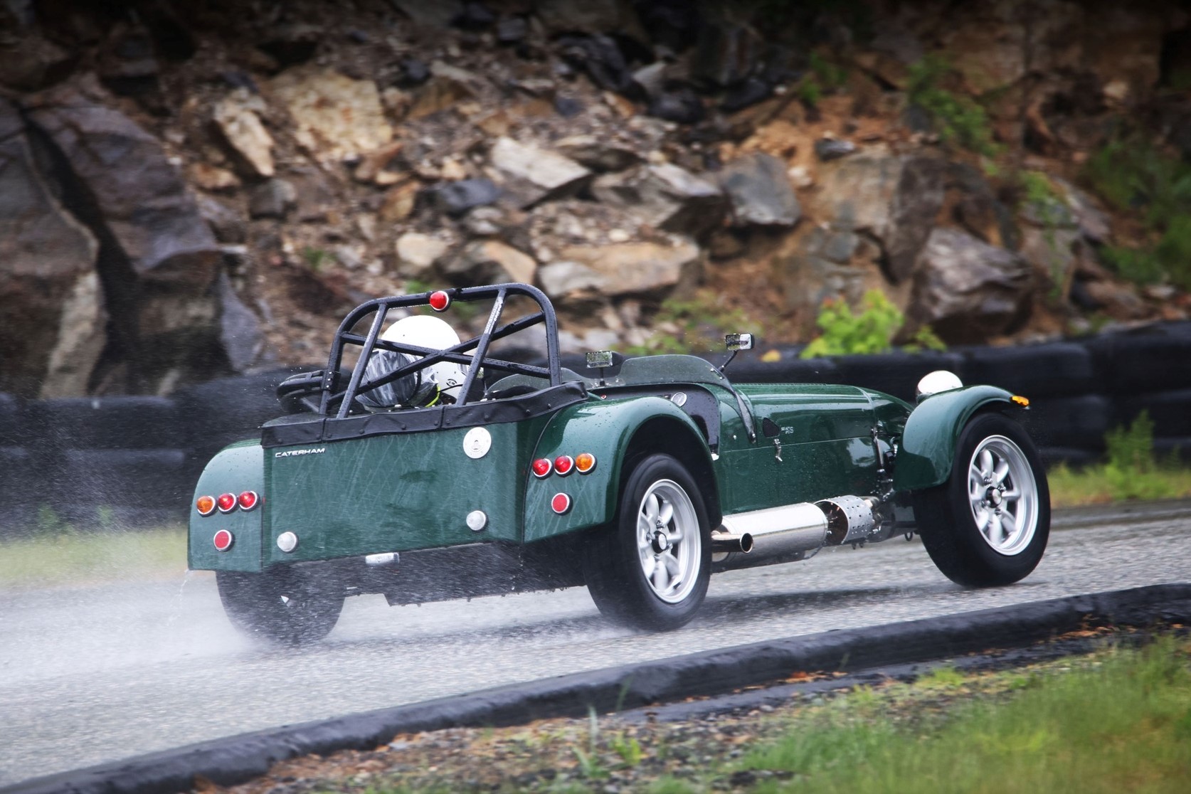
Some photos from LRP, Palmer, and NYST.
-
It's been so long since I assembled my car that I don't remember where the bolts were, but I would assume they were with the hub and not in the steering wheel box. There's always a chance that you didn't receive them. My kit was missing the DeDion tube and other smaller parts! If you can't find them in your kit, they should be M6x1.0, 20mm long, flathead. Something like this: https://belmetric.com/flat-socket-head-10-9-black-m6x1-0-coarse-din-7991/?sku=SF6X20&gad_source=1&gad_campaignid=21943007182&gbraid=0AAAAADn8Oc9IUypOzgbX_g6-4xkVOmU4y&gclid=Cj0KCQjwss3DBhC3ARIsALdgYxNmqDkF__S4icEZ1e5GPLEzatwPY1bq5YY5CrHT3N_bjUu-09WtfVAaAoqSEALw_wcB
-
I used that same oil temp gauge in my old Birkin and it worked well. It did show how much longer it took for the oil to heat up compared to the coolant. I think I used one of the metric adapters to mount the sender in the drain plug location.
-
They actually worked very well, and were used on many early British sports cars and race cars. I found them to be very accurate and the only downside was the cost, and the capillary tube near the cylinder head had a tendency to fatique and break. You had to coil up the capillary tube to give it room to move when the engine rocked on the mounts. One neat thing with the mechanical gauge was the temp range was 90-230 degrees F and if it was a really hot day they would show the actual outside temp even though you hadn't started the car yet.
-
Here's one from my visit there. Wish I had centered it better.
-
Please Review These Build Specs: 420R
11Budlite replied to rider's topic in General Sevens Discussion
The 420R should come standard with LSD. -
Is that yours???
-
The Regular Summary of Classified Ads of Se7ens Found For Sale
11Budlite replied to Croc's topic in Cars For Sale
New one on BaT: https://bringatrailer.com/listing/1989-caterham-seven-1700-supersprint-2/ -
With the standard Caterham seats you can just bring the crutch straps on top of the seat cushion and sit on them. It worked fine for me and I think others have done the same. Just an FYI, I have the lowered floors. Not sure if that would make a difference, but I installed them using pg 149-151 of the assy guide as reference.
-
Considering the way a 6-pt harness works, I can't understand what the point of a 7-pt harness is? Maybe some one can educate me on the benefit, but until I hear more I would always go with a 6-pt. Looking at a 5-pt harness from a guys perspective doesn't make much sense either.
-
I would do the same.
-
Just announced that there are going to be 25 more Caterham 310 models produced with the Sigma engine. None of the standard colors are used but they're offering 6 special colors/graphics. Being priced between the 360 and 420, I think you'd really have to like the graphics to choose one over the Duratec models. https://caterhamcars.com/en/models/the-range/seven-310-encore
-
I just logged on for the first time after a long weekend MTB-ing in VT. I think the new logo looks great! Thanks to all for your efforts!
-
Some real competitive racing from the Caterham boys in the NW:
-
It's a brand of aftermarket flywheels and other parts: https://fidanza.com/fidanza-00-04-ford-focus-2-0l-z-tech-5-speed-aluminium-flywheel-186991/?srsltid=AfmBOopF6jxC5URC2tuvcxAR4dZ5e2JawZq2e80t1CppYJdR3DNHwSjj I'm sure it was a rarity, but I had a rather negative experience with Fidanza 15 years ago:
-
My first thought would be something with the float too. It might not be related to your issue but I figured I'd share my recent experience just in case. I was having an intermittent issue where sometimes my gauge would work and sometimes it would always read empty. I recently pulled my FP assy out and noticed that the variable resistor component had a crack in it. It's hard to see in this photo, but it's all the way through the plastic with a fine break in the electrical/resistor part. Unfortunately the sender portion is not available seperately so you have to replace the whole FP assy. I'm not sure how it happened because I don't drive it on the street with all the potholes, and I hardly ever use the curbs on track.
-
I'm not sure how you could modify the stock FP pickup to get it lower and moved to the center, if your FP is like the one in my Sigma-powered car. My pump looks something like this: You might consider modifying the assy to something like what John did on his car. Check out pg 3 and 4 of his build thread here:
-
Switching from 14" wheels to either 13" or 15"
11Budlite replied to greasymonkey's topic in Wheels and Tires
The most common wheels with a 4x3.75" PCD I believe are Triumph Spitfire. There should be plenty of wheels available, either stock or aftermarket aluminum. Vega wheels had a 4x4" PCD like the Sprite/Midget. -
Thanks, it was a lot of work. Unfortunately once it's installed you can't see it!
-
Since I sent out the simple parts to be fabricated to SendCutSend, I figured I would do the more complicated parts myself. I've been trying to decide how to mount my Tillett seat and had run across one method someone in the UK had used that I though might work okay for me. He used two aluminum angle pcs per side with a pivot so you could adjust the angle of the seat. Everything I had read seemed to recommend the front of the seat about an 1" higher than the rear. My first mistake was using 1" x 1" aluminum angle for both the upper and lower mounts. I thought that the lower the seat was, the better. Well, my first track day confirmed otherwise when I was having a dificult time seeing the apex on some of the corners, specifically turns 6 and 13 at Palmer. So when I got home a slight redesign was in order. I used the original upper mount in 1" angle, but bought some 2" angle which I cut down to 2" x 1.375". Both upper and lower aluminum angle is .1875 thick. Did a quick mock-up and raising the seat an inch put my sight line where it needed to be. Having the seat raised up also gave more room for the crotch strap to be routed under the seat. So I took it all back apart and started laying out a pattern of lightening holes to see where I could save some weight. All holes were center punched, pilot drilled with an 1/8" bit, center drilled, final drilled with a few different carbide tipped hole saws, then chamfered. There are also (5) different mounting locations to move the seat forward or aft. All hardware is aircraft grade (other than metric to mount to the seat) and I used T-bolts with a tight fit to the lower rail so they wont turn when tightnening the seat mounts to the floor. So far it's worked very well, although the seat fit is unbelievably tight in the cockpit of a S3 chassis. Just 1" more width in the cockpit would make installing the seat and adjusting the lap belt so much easier. I saved right around 2lbs over the standard adjustable seat rails which weigh a little over 4lbs per set. That's for one seat. The following photos show the result.