
copy.jpg.dd4bdbb41ccb3ea8a585d1ad217ef61b.jpg)
.jpg.da03509438cc84820b8cf5d64db570ab.jpg)
Austin David
-
Posts
391 -
Joined
-
Last visited
Content Type
Profiles
Forums
Store
Articles
Gallery
Events
Library
Everything posted by Austin David
-
you can compare a [Caterham] to every car every made, but not to another [Caterham]. My primary concern is that huge gap at the back of the filter where you might be able to see guts... if you're standing within 3'. Yes, this is NOT A REAL PROBLEM. I'm just trying to figure out the boundary between "you definitely need to cut more" and "now you're just showing off".
-
bonnet OFF, air filter "open" (no tape): IAT is now a function of speed, range was 27-34c, ambient about 20-25c. Very little deflection with RPM. For various reasons I didn't get a lot of data, but the data I do have shows 13.20 and 13.38 at two points, with 1.0 trim -- in line with "a little bit of tape", but without the better heat management. The steps are degrees C, and the rise is about 2-3 C after the radiator starts dumping heat, then tapers back off with the airflow.

-
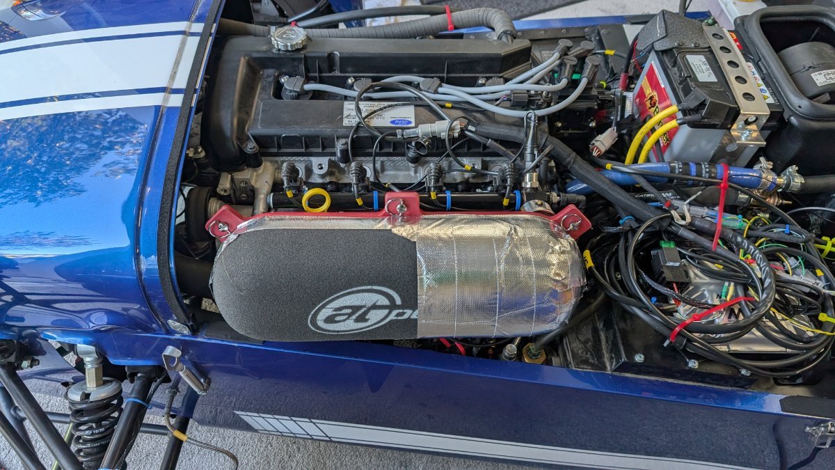
For reference: this got me started, and represents the minimum cutout to fit the bonnet. Cyls 3, 4 are still under hood, only trumpets for 1/2 are exposed. Here's a shot of the fully-taped filter, which mostly matches the above bonnet cut: ignore the wiring and ignition coil, that will eventually come back out. Some details in my build thread. This configuration has the best heat management, but appears to restrict some airflow at WOT. 1-2% average enrichment + 1% fuel trim (out) from ECU. Under throttle the IAT drops back to ambient, reliably. Throttle > 98%, 7k RPM, average AFR is 13.19 + 0.99 fuel trim. Target is 13.2 Finally, a shot of the bonnet as cut right now: You can see the edges of the tape just inside the penetration, and removed up to the trailing side of trumpet #4 under the bonnet. This setup seems to balance heat with much less restriction. 13.16 AFR @ 7k / 99% throttle, 1.0 fuel trim. with tape 100% removed: 13.33 AFR, 1.0 trim -- concluding this runs a little more lean, less restricted. IAT is also 45C vs 25C (with partial tape), not clear how much difference that should make. The AFR differences are definitely subtle. IAT and temperature swings with throttle (not speed) are much more dramatic.
-
It's hard to un-cut, so I've been making progressively larger holes and trying to prove I need more. There aren't any close enough to test, I live in the sticks But I will be testing with zero bonnet, to at least get a baseline set of measurements with zero restrictions
-
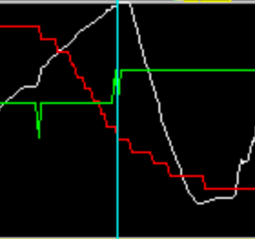
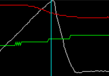
I've been replacing my perfectly fine stock Caterham 360 intake with ITBs, and in the process have been figuring out a good balance between mangling my beautiful car, max airflow, and minimum heat intrusion. I happen to have a lot of data available from my ECU, as I'm also tuning it, so I'll share my findings here. It's not what I was expecting. My engine is a "stock" 360 with the milder cams. The entire intake has been removed and replaced with an ITB setup from AT Power, with ECU from ME. In this investigation the most interesting part is that the air filter is a vanilla pipercross-style aluminium backplate + foam filter, and is not isolated from the engine bay. IAT sensor is at the top of the backplate between trumpets 2-3, not far above the throttle cable. For this data (and until otherwise specified) the bonnet is cut from before cyl1 up to about cyl3, where the filter remains under the bonnet-line. Measurement: WOT run in 3rd at 7k RPM, tracking IAT, Coolant, AFR, and lambda trim. AFR is measured at the collector, an average of all 4 cylinders. GENERAL findings: - lots of heat intrusion from the engine bay, like, a LOT. With the filter open, IAT rises about 20C above ambient (25 ambient, 45 IAT) and mostly stays put. No significant drop at WOT, and it stabilizes about 20C over ambient. This was repeated before I started recording, which led me to try blocking engine heat. - taping half the filter (pics below) will totally cure heat intrusion, but restricts airflow a little. More analysis to follow - just taping the sides of the air filter, particularly around the sides behind the horns, MOSTLY cures heat intrusion with measurable, but relatively little air restriction. white: RPM red: coolant temp green: IAT Bonnet in place, no taping on the air filter: - no IAT deflection with airflow - rises continuously, I suspect from the heat dump off the radiator at speed Bonnet in place, air filter taped around the sides + short of #4: IAT drops with airflow Bonnet in place, air filter taped up to cyl 3: note that IAT bottoms out to the minimum value, ambient. This happened at every WOT event
-
.thumb.jpg.885191d302e6c3704c848a8f5ac3a612.jpg)
420S Rainy Season Build in Western Washington
Austin David replied to Timberline's topic in Build Threads
I was recommended carpet tape, and it was a great call. I've pulled it up at least once to add my seat heater wires. I never used the set screw. "That ain't goin anywhere" works pretty well. Also the tunnel cover is captive while the seats are in, OR while the gear knob is on, OR while the e-brake is down. -
they used a controller because they're (I assume) not running the pump at full blast, AND they don't have any active pressure management. Without more information I could only guess, but I assume the ECU is sending some sort of predictably-variable duty to the pump, like based on injector duty. That's what I'm doing, but I also have some amount of pressure feedback and monitoring.
-
Some minor catch-up to share my joy. First, the good: I've been pulling a lot of logs and I can see (measured) 0.1s between throttle open and RPM leaping. Throttle response is VERY fast at idle, where the original plenum had a noticeable lag. The plenum lag is probably fixable with tune, but not doable on the locked factory ECU. When it works (see below) it does work well. Throttle response is what it should have been from the start, sound is great, and torque is stronger at very high RPM. The stock 360 kinda started falling off at 6500-ish, this tune pulls through to 7k. I have not tested, but there is an ignition cut programmed at 7400. I also got a free* knock sensor, which does seem to work well by default. Very little actual knock, but I've found a couple events including the one I looked for. Learnings: 0) "sharp tools" are important. In this case it means a laptop, software for log analysis, experts ready to help (remote tuner), and literal tools for repinning cables, properly making terminals, etc etc. 1) the ECU probably doesn't "matter". If doing this again, I'd pick my tuner and hardware kit (intakes, fuel management, etc) THEN select an ECU recommended by the tuner. That said, I am getting good support from overseas, though with a lot of overnight-waiting. 2) science is important. This would be easier if I knew what the "baseline" 360S acted like: fuel pressure, AFR at RPM range, etc. The "factory tune" might not be perfect, but with all this new control and measurement I am tempted to make the new tune perfect. Hard to tell how "perfect" it needs to be, to be better than the factory tune 3) there are a lot of variables, and some things that can only be done once (like cutting a hood) and some things that can be re-done without too much cost, like making a custom harness or cutting an air filter backplate. This would have been easier, and maybe 5% more expensive, if I'd planned some of these ahead. Some annoyance, which led to delays but probably not show-stoppers: - alternator electrical noise... and while troubleshooting, seem to have led the ECU to dwelling on plug 2 which fried the driver. Couple days of troubleshooting + offline exchange, but will be getting a new ECU (see above, excellent support from ME) - maybe ignition noise, TBD. infrequent "lost sync" events at ~ 4k RPM. More data required - to work around the fried driver, may (temporarily) run a traditional coilpack + wasted spark setup. I assume I'll eventually go back to COP - assuming the alternator noise persists, I'll go with a 1-wire "Denso" style option. Appears to be a 90mm / "mini race" alternator, they run $150(ish) for 55A or ~75A.
-
420S Rainy Season Build in Western Washington
Austin David replied to Timberline's topic in Build Threads
My 2021 order came with a new motor dated 2017. A 420 would be fresher but these just don't sell that fast. I too had some funny rust I wasn't expecting... After a few miles and rainstorms it seemed to matter less... -
FYI I manually checked timing, the crank sensor appears to be rotated 275*, where the ME map expected 265. I also saw reference to 255 in other docs, so ... reminder to double-check what you think are sensible defaults.
-
needs a good home: 2L Duratec intake parts
Austin David replied to Austin David's topic in Parts For Sale / Wanted
a home has been found -
Push-button replacement for Dzus fasteners on Caterham nose.
Austin David replied to pethier's topic in General Tech
I used a leftover washer from my build for 2 years. I don't pull the nosecone much so it was tolerable. I tried making a tool using a penny but the penny bent (!!). I acquired a larger, hardened washer recently and filed it to the right thickness, but that's not much better than the first washer -- it's hard to align under the cone, and hard to get much torque on it with my knuckles. A few weeks ago I got a "coin" driver; it's easier to turn, but basically has all the same downsides with alignment etc. I may get annoyed enough to try @wdb's butterfly on the bottom. The top fasteners work ok with a washer. -
Leftover parts after an ITB installation, all from a 2021 360S -- 2L Duratec - air box & filter, throttle body w/ TPS, plenum, mounting hardware - fuel rail & injectors - decomposed wiring harness for these (ie mostly the plugs & pigtails) - MB ECU -- locked from Caterham Any / all for the cost of shipping.
-
@wallisek did you get it sorted? there are a few methods, it's annoying but a good excuse to go for a ride. I personally just ran at 70 mph indicated, used a phone GPS app, then did some light math to compute a new PPU. Did that a couple times, it's perfect.
-
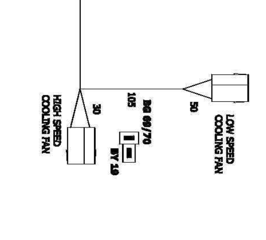
Page 216 in the 2015 manual has this (attached). It shows two plugs so I'm guessing there's a second fan in some version of the car? My fan definitely only plugs into one of those two.
-
awesome! I am by no means an expert but my understanding is that this bumps a 360 up to 420+ spec (420 cams + better intake). Vanilla 420 would be ~ 210HP.
-
you say roller barrels and cams; is that basically the 420S upgrade kit?
-
Is the fan a single- or two-speed fan? I notice the electrical diagram shows two drops for high and low speed, but my fan has only two wire connection and as far as I can tell it's wired up to the cooling fan relay directly, which I assume the former ECU controls/ed with a simple on/off. As in, with the ECU disconnected I can ground the correct relay pin and the fan comes on and sounds fairly loud, and I don't see any obvious second circuit for a higher speed. Car is a 2021 Caterham 360S (Duratec) with new electronics. On OEM electronics it behaved "normally" as in "fan cycles at idle" between 90-95C" and I feel like it was very much on/off but I did not test it before I ripped out the old ECU and harness.
-
ok, for future sleuths: - it's on purpose - it should get hot while the little battery light in the tach is ON -- ignition on/engine off, or alternator no worky - it should not get hot while the engine is running normally (light is not illuminated) - it's there because the LED in the tach doesn't draw enough current on its own, so this will sink a few W (2? 5?) to keep the rest of the system happy. Thanks @sltous, I wasn't able to find that set of articles.
-
Yes! The batt light on the tach gauge comes on when I disconnect the resistor while running. I also noted it's not hot at long idle, but definitely gets hot if I leave the ignition on with engine off. Other than the battery light on the tach, everything seems fine with the resistor out
-
about 25-30 mph seems to muffle that beeper just fine
-
Some light googling says this might be something about LED lighting in the dash, and providing enough resistance to look like incandescent? But if I unplug it, things seem to work as expected. it gets HOT to the touch -- again, googling sort of indicates this is expected. 10k miles in and it doesn't seem to be causing any trouble, What is it? Is it important? It lives approximately above my steering column.
-
The first time I saw the interference I had the crank sensor line run a totally different path, nowhere near the alternator. It doesn't seem like it's interference from the control line? And, as near I can tell, those two lines are just a battery sense and the warning light on the dash, so I don't know why they'd even be noisy...
-
quick: notes: I think I've got everything sorted and am ready to start test driving. tl;dr: it was harder than I expected but definitely not out of reach. The ME221 was a good choice. CANchecked also good and would recommend standalone. Expect to use a LOT of wire, crimps, connectors, loom, heat shrink, etc. Invest in a crimper, good connectors, etc. - Alternator is noisy when plugged in (triggers false signals in the crank sensor), but the noise does NOT appear consequential. When disconnected it wasn't charging in any meaningful capacity, when connected it charges at idle. ECU still showing full 720-degree sync with the noise, I'll continue to monitor. - fuel pump : the driver module (old ECU harness #33) can be driven via PWM, 500 Hz signal. 5-50% duty -> 10-100% pressure. I wired in a 0-100psi sensor to the former MAP sensor lines, MEITE has a section for the fuel pressure sensor. I use a GPT to drive the FPDM from 35% - 100% based on ignition duty, or "off". The FP relay is wired to the ECU (low side output to fan relay), but currently just slaved to an "always on" signal. This has the FP prime on ignition on (default behavior from FPDM), then start when the engine starts turning. Added a mechanical gauge to help calibrate, but the expected calibration was correct: 0.5v - 4.5v == 0-100 PSI. - cooling fan: wired a second output (low side) to the fan relay, very simple on/off - tach: same 1-per-rev as stock ECU, plugged into former ECU pin 44. - throttle: the original cable doesn't even sort of work, and would hit the air filter backing plate. I got a 90* bend fitting, a make-it-yourself cable set, and a 1.5mm nipple from Amazon. Had to cut down the elbow to fit the throttle hanger on the ITB, then tap it for 5/16" (the nearest-size die I had handy). The pedal side was too small for the firewall hole, but a layer of heat shrink holds it still, with a nut to keep it from pulling through. The nipple doesn't fit inside the pedal tube, but the wire passes straight through and I snugged up the nipple. Full pedal travel (and more) for full TB sweep. - standard kit assumed EU-style Duratec, which uses external plugs. ME supplied a COP adapter harness, but basically just IGN1-4 + one wire, out to each of 4 COPs. Simple to set up, otherwise. - I opted for uprated 330cc injectors but probably didn't need it. The new fuel rail is much, much prettier though. Old rail is out, old injector holes are plugged with supplied injector-shaped plugs (provided with the kit) - I ended up basically rewiring the entire engine. This would have been easier with engine out, but was easy enough with coolant out (that top tube). The old ECU harness is tucked pretty hard up under the tunnel, which itself is insulated. I elected NOT to pull anything I couldn't reach, and will get to it if/when the motor is next out. Hopefully never. - In retrospect (see above) the only sensors and harness I reused were for the oil pressure gauge and starter/alernator. IF I had motor out (and the good fortune to do this job again) I might have saved time making a harness from scratch and just disconnecting everything from the factory. - CANchecked is the unsung hero here. I replaced the temp gauge (external submarine) with an MFD15. For reasons not yet determined either the gauge or the ME doesn't correctly terminate CAN, but a 120-ohm resistor at the gauge side took care of it. I had already added an oil temp gauge in the pan, and wired the "submarine" water temp gauge directly to two analog ports on the MFD15. I still have all my original Caterham gauges save one, and the "new" temp gauge now shows all sorts of cool things. Including temperature - while under the scuttle I rewired my AUX stuff for the 12V plug / USB charger, seats, roll bar light. I moved it all over to driver side, above steering wheel. Ran a ground lug through the firewall on the steering column brace, which incidentally helps stiffen the firewall. Cut a ~ 1" penetration in the firewall and made a shrouded grommet. Put 5 AUX fuses inside + relay (keyed to ignition), and 6 hot fuses outside on the firewall. Also moved my horn power line to the new fuse panel, previously on the hot side (above passenger footwell). It's much cleaner than my previous job, but required removing the scuttle to set up, and losing the original airbox. - new ECU is mounted on a custom mount (3D printed) on driver side footwell. For now I've removed the shims and lowered the battery, but it's on the same sheetmetal mount. - the oil dipstick (wet sump) needs a new home. Parking this to sort out "later". - have not yet cut the bonnet. The air filter plate was NOT cut. I ended up making a template (3d printed), then used that to locate the centers of each stack, then used a 60mm hole saw ($18, Amazon) and drill press with lots of clamps and a spoil board. Worked perfectly, but took me a couple days to figure out. The IAT is mounted in the center near the top, basically just in front of the throttle cable.
-
catching up: the ME221 takes a fuel pressure input, but it's not particularly prominent in the interface. This input appears to do the right thing, when calibrated. I put a 0-100 psi sensor on the fuel rail, along with an analog gauge, and calibrated the fuel pressure sensor. I've got the fuel pump driver module (FPDM) working and slaved to a general purpose table, driven at 35% idle, which corresponds to about 40 PSI, then linear up to 100%. That table's input is injector duty, which I figure is the most linear guess about fuel pressure demand. I assume there will be some tuning required, I doubt to see such a linear relationship between FPDM duty and fuel pressure.


.jpg.fd7f251e50be4f9b7835ae6cb958cee7.jpg)