copy.jpg.dd4bdbb41ccb3ea8a585d1ad217ef61b.jpg)
.jpg.da03509438cc84820b8cf5d64db570ab.jpg)
Austin David
-
Posts
416 -
Joined
-
Last visited
Content Type
Profiles
Forums
Store
Articles
Gallery
Events
Library
Everything posted by Austin David
-
.thumb.jpg.885191d302e6c3704c848a8f5ac3a612.jpg)
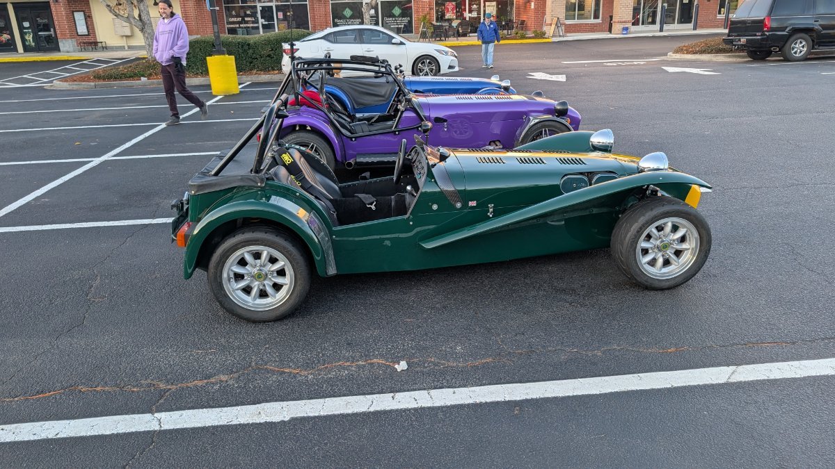
Photo of your car you took today
Austin David replied to Xhilr8n's topic in General Sevens Discussion
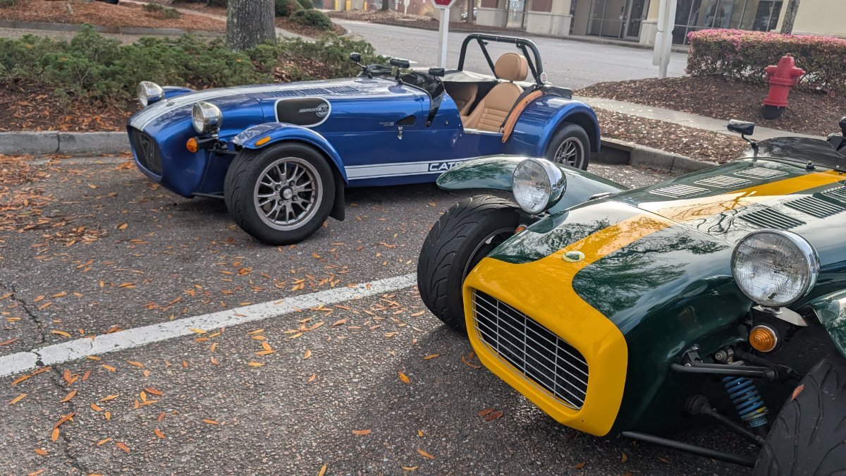
Quick meetup with another owner in town, I don't think he's on this forum. The BRG with wings is so nice...
-
My alignment guy is 5 hours away and I have more than one car But it's 80% toy, like the rest of my garage
-
I pre-ordered a G2. They claim it can square the dedion. I'll post a review when it comes in, in 8+ weeks
-
Have you used it yet?
-
Do you have a half hood for your Caterham?
Austin David replied to Saudio's topic in General Sevens Discussion
I have the Caterham half hood. It buffets BAD at speed. The idea is great but it's pretty tough for touring, the flat windscreen doesn't help. Instead I load up with head/face/arm covering, works well in summer. Basically hiking or fishing gear. -
light update: I changed the throttle linkage. The ITB kit I got came with "center pull", which had the cable enter about horizontally from the intake manifold, directly at the filter plate. Probably fine for many applications, but not this one. I made it fit with a relatively tight 90* bend. This weekend I swapped out that linkage with a "left pull", which points at the front of the car. Got a new cable, and shortened it dramatically, to run from the pedalbox under all 4 trumpets, then up and around to the new cable holder which is between #1 and #2 trumpets. There's tons of clearance there, with the rest of the linkage between cyls 2/3. I underestimated how much friction my tight bend added; the new linkage has a very light pedal feel. Because I didn't change the TPS or the actual blade position on the ITBs, there was relatively little calibration involved. I did reseat the connecting bar between the left 1-2 bank and the right 3-4 bank, so I should double-check the vac, but startup and idle (hot and cold) are both exactly what I expect.
-
Interesting build. Spare tire and tonneau cover, but also 4-point harness. I love it
-
... And an uncolored one for a Miata.
-
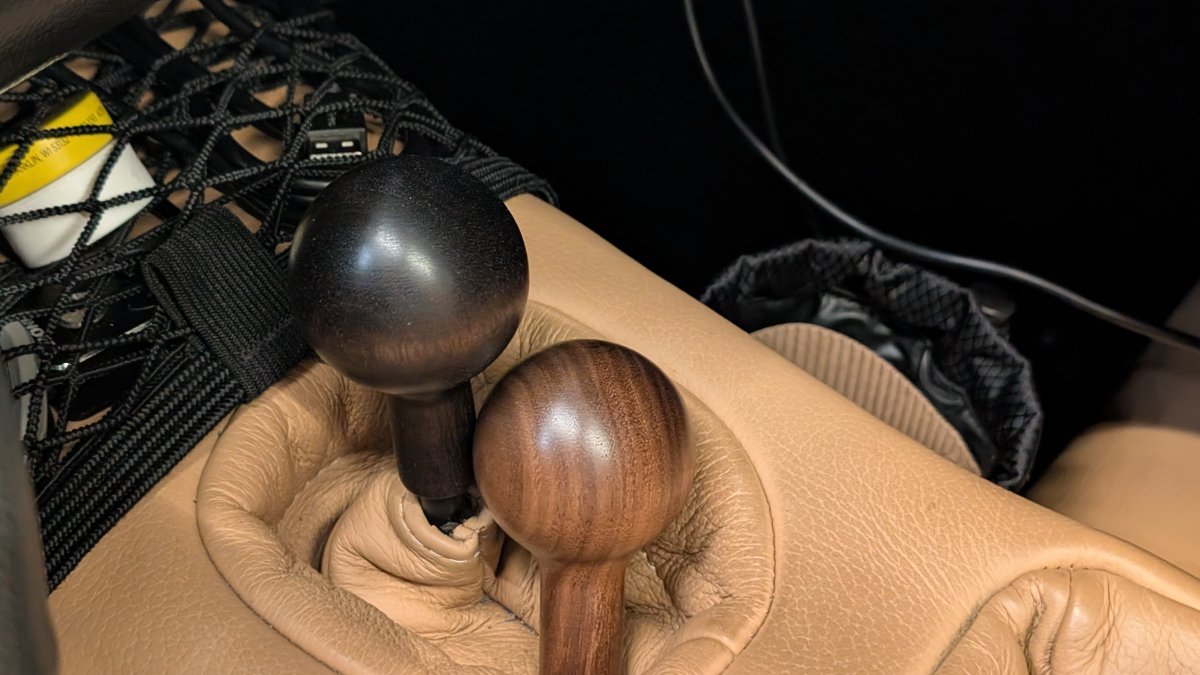
Black walnut, colored with vinegaroon -- not really a dye, and still lets the grain come through subtly.
-
I've seen those; his work is amazing. I actually have a "plan" (parts list) for maple & walnut to match my triple stripe, but I'm waiting until I get the solid walnut before I make more changes.
-
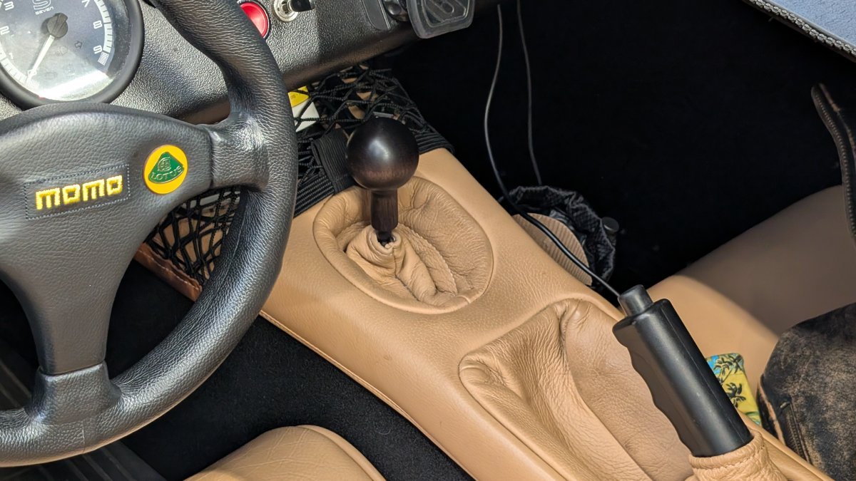
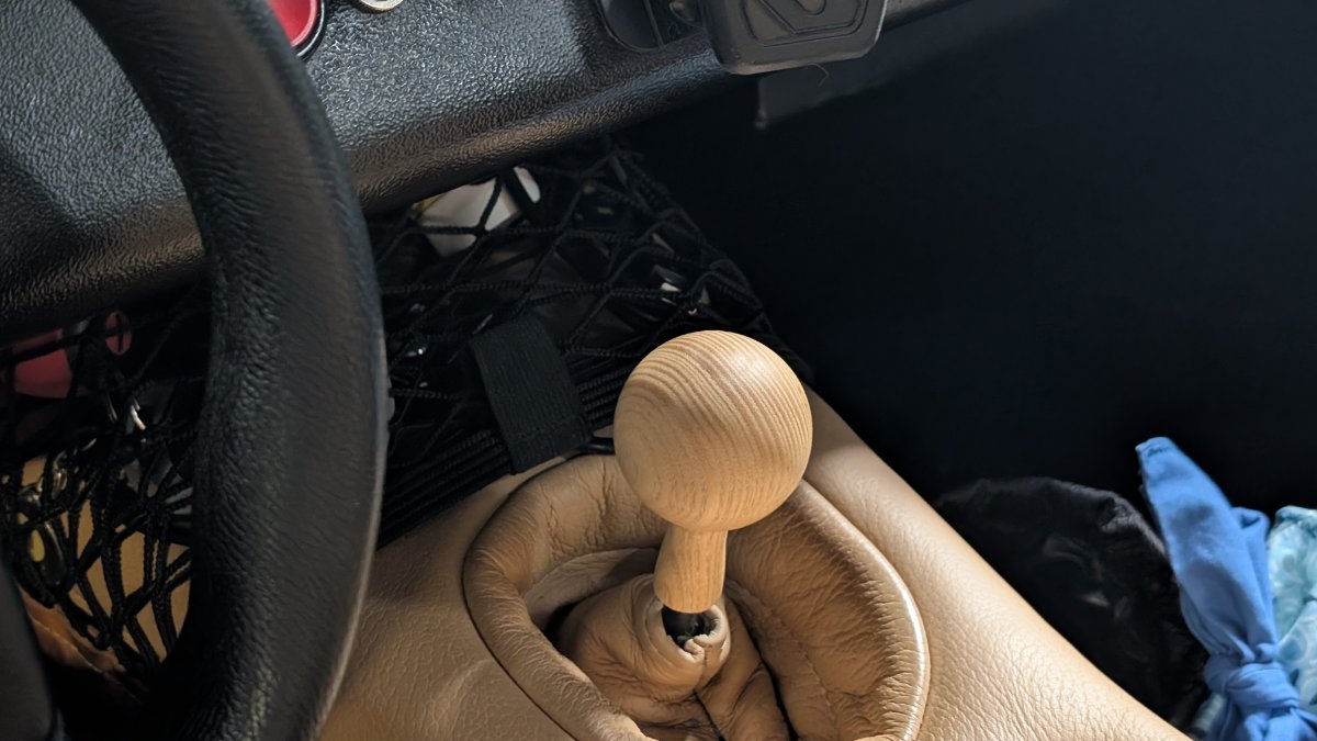
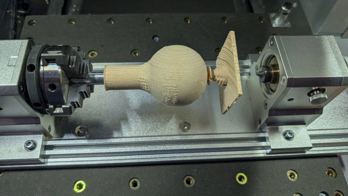
I made a better shift knob. My S3 has little clearance to the dash, I don't care for the metal knob for several reasons. And I like wood. With this I'm able to get exactly the size, shape, position, and material I want. The current prototype is made from $5 ash, 1.0 will be black walnut. The process is a little tedious, but I'll share some details for future reference. Worked with @JohnCh to compare notes. 3D printed a lot of knobs. John noted that a 2mm diameter difference has a meaningful change in "hand feel", and I definitely agree. 45mm feels small, 50mm feels big, my "just right is at 47.5mm (before finishing). Final product is CNC'd in solid wood and hand-finished; details below. I personally like a long "neck" or skirt, and I don't like seams. This is a road car and in Charleston I ride 10 mos / year without gloves. To avoid bulk I dropped the standard brass insert and tapped the wood directly (details below). Ditto, there is no locknut or set screw -- it attaches and stays "clocked" on with friction, but I may use a little RTV to help manage vibration In final installation I'll put a small soft shim under the shift boot, to hold it flush with the lower part of the knob and hide the stick entirely. "final" product, pending my black walnut: Production: acquire or make a slightly oversized block; 2x2x6" ash, for instance. Square one end, this is the bottom surface. carefully drill an 8mm pilot hole to about the appropriate depth up from the bottom, centered and aligned. Tap it to 10 x 1.5 or whatever is appropriate. Drill out the lower part to about 10.5mm (or larger for a different transmission) to accommodate the unthreaded portion of the stick. I was able to run the pilot on my bench with hand tools, there's some room for error. inject liquid CA / superglue to coat the interior threads. Give it a few minutes, swab it out. Drying can be accelerated with water and rubbing alcohol. Do that again for good measure. When it's dry, run the tap again. Make a "sacrificial arbor" with a 10x1.5 bolt by sawing off the head. Screw in the arbor, fix it in the chuck & align to the bottom surface. Machine on that arbor. I ran a pretty gentle process to keep from overstressing the threads, but I think I had a lot of margin for error in here -- there are about 20-30 threads in contact at this point. Finish in place, then remove the sacrificial arbor and remount on the stick. Done! Frustrating limitations: I'd like to have machined the bore & threads, but my setup doesn't have enough Z-range to get a bit 2" deep into a 4" part. I'd like to have a hidden jam nut, but the threaded inserts & nuts are about 15mm across. I could maybe machine slightly smaller nuts and inserts, but that's still eating up about 4-5mm of "budget" in a place I'd like to keep small
-
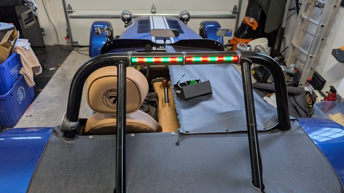
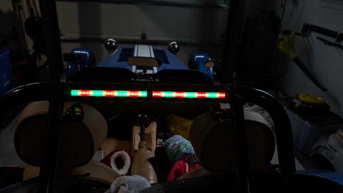
Rollbar Lights -- custom animated run/brake/turn
Austin David replied to Austin David's topic in General Fabrication
I'm open to building several at cost, as long as they're all at the same time. IIRC the econoseals were the hardest to figure out. -
Rollbar Lights -- custom animated run/brake/turn
Austin David replied to Austin David's topic in General Fabrication
A quick daytime video. I didn't screw with HDR much, but the camera kinda washes out the LEDs; it's more obvious to the eye. rollbar light - SD 480p.mov -
We won both the pregame and the main event
-
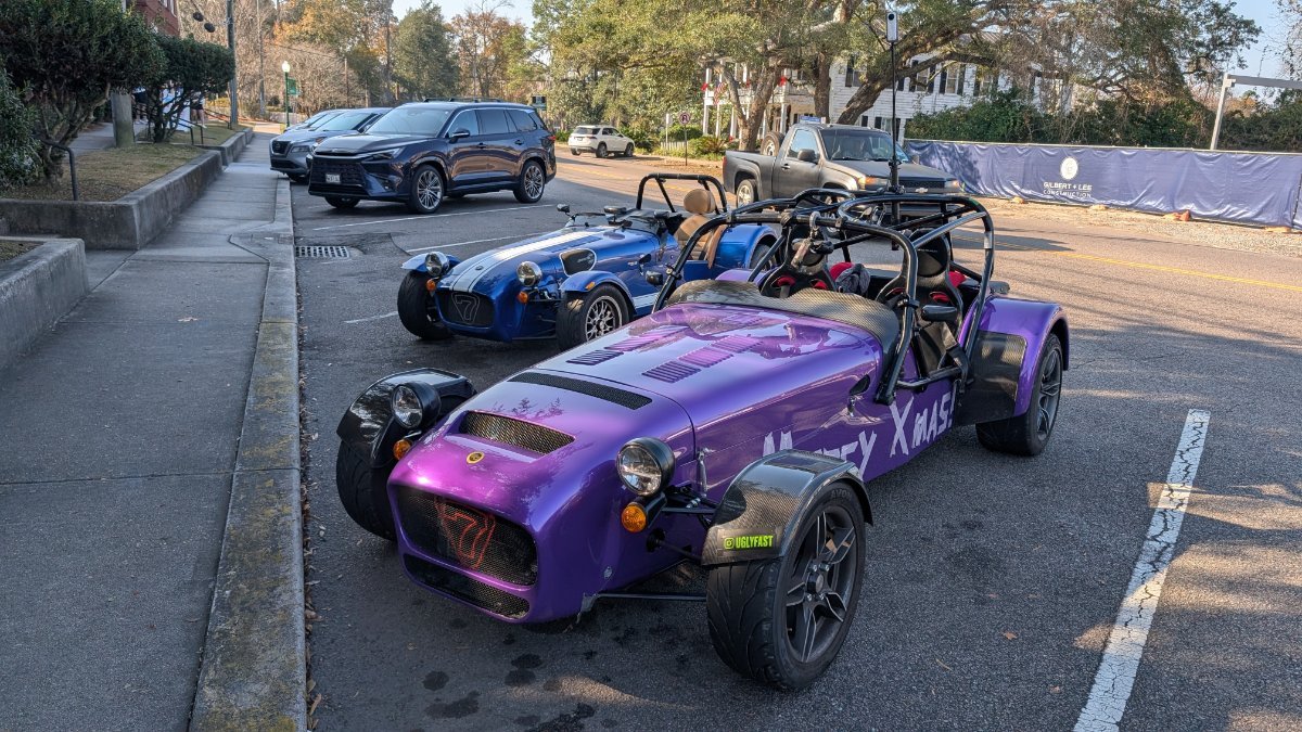
Photo of your car you took today
Austin David replied to Xhilr8n's topic in General Sevens Discussion
... and then there were three! Finally connected with another local owner this morning. Beautiful little crossflow
-
It's the forced perspective which makes the S3 look like a biggish car
-
FYI he made it and we're hitting Cars & Coffee tomorrow AM 12/27
-
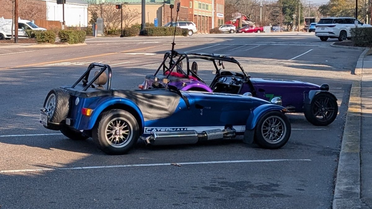
Photo of your car you took today
Austin David replied to Xhilr8n's topic in General Sevens Discussion
Saw @UglyFast because his in-laws are down the street...
-
A writeup of my run/brake/turn lights across the rollbar. For history, here's my first attempt: - Econoseal male/female Y-cables to insert between the tail lights on the corners, for the run/brake/turn signal - 12v from a switched ignition line for power My first setup was a pair of inexpensive run/brake/turn lights from Amazon, wired in via those econoseal. I wired only one signal on each side, so when the left blinker was on only the left side would blink. It worked fine, but the lights just didn't last long and a few LEDs went dead within a few months. I'm sure the CaterLED uses much higher-quality parts, but I believe the setup is similar: LED strips wired directly inline with the tail lights, and powered directly. I then swapped out the lights, and wired in a microcontroller. I added a 12v-5v converter, a several-channel opto converter (for switching 12v-ish to 3.3v or so), and wired it out to an addressible LED strip. I used an aluminum channel with frosted lens, and designed some brackets to hold it against the rollbar. The MCU program uses the run/brake/turn signals: - a run light is always on (when powered), dim red. When the tail running light is on (ie, headlights) the run light dims slightly. Brighter during the day, not so overpowering at night. - brake lights pulse for about a second, then solid red. very bright. - left/right turn signals are on the left or right third, and animated The MCU, coupler, and converter are housed in a small box in my boot, with wiring running up one stay to the roll bar. It's weatherproof and unobtrusive, but also really bright. I'll post some followup day and night videos to see if i can get just how bright they really are... The funny part: last christmas (2024) I coded a "christmastime" mode that makes the run light alternate red/green. It automatically comes on in the month of December, otherwise is solid red.
-
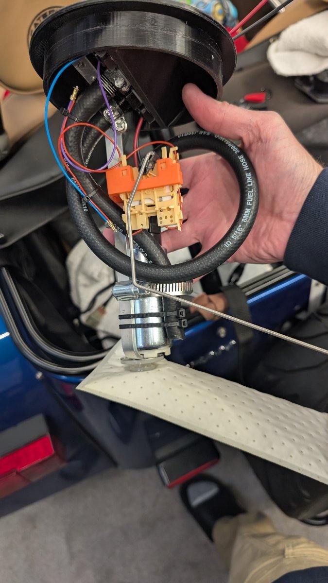
@MV8: measuring at the sender in ohms, with my fluke held in bare hands. The values are probably pretty good, but may vary at the gauge "empty" -- could still draw fuel and run, but gauge at the bottom of sweep. 111 + 2.5g, gauge reads slightly above 1/4: 219 <driving around a lil> +3g (estimate > 5g in tank), gauge reading above 1/2 (not settled): 341 +2.5g / full: gauge F, 464 ohms
-
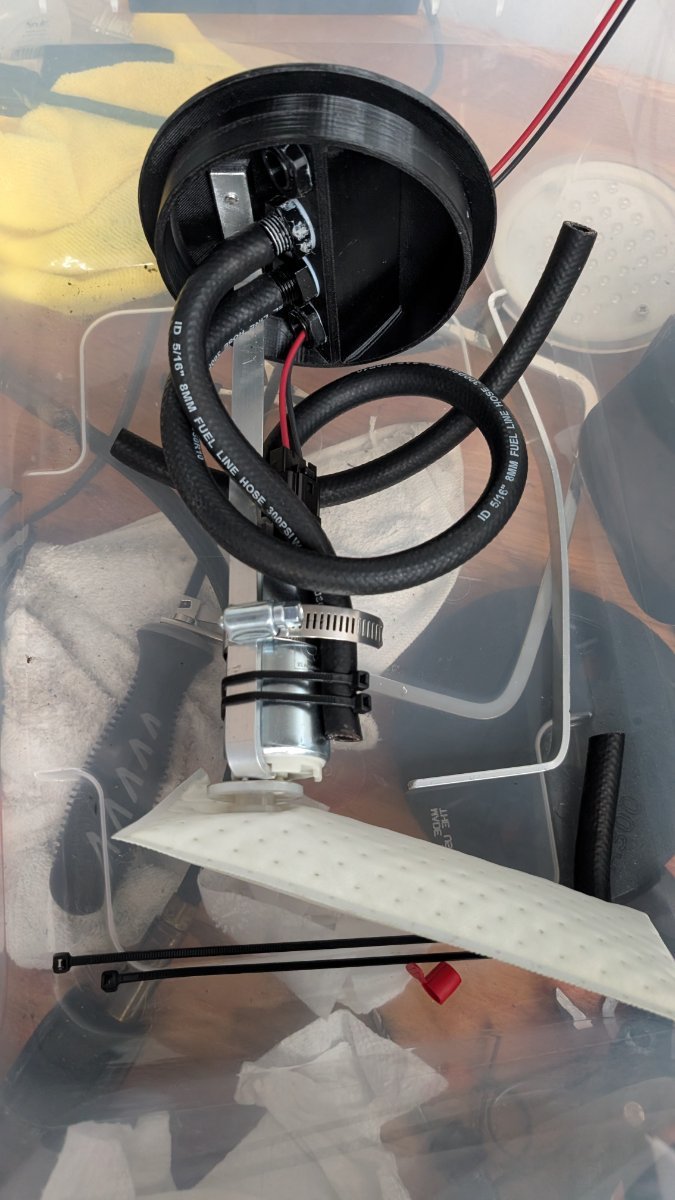
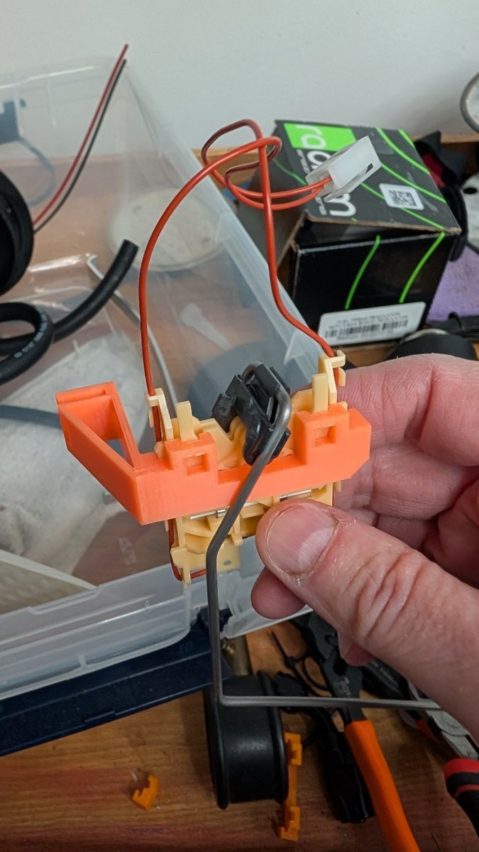
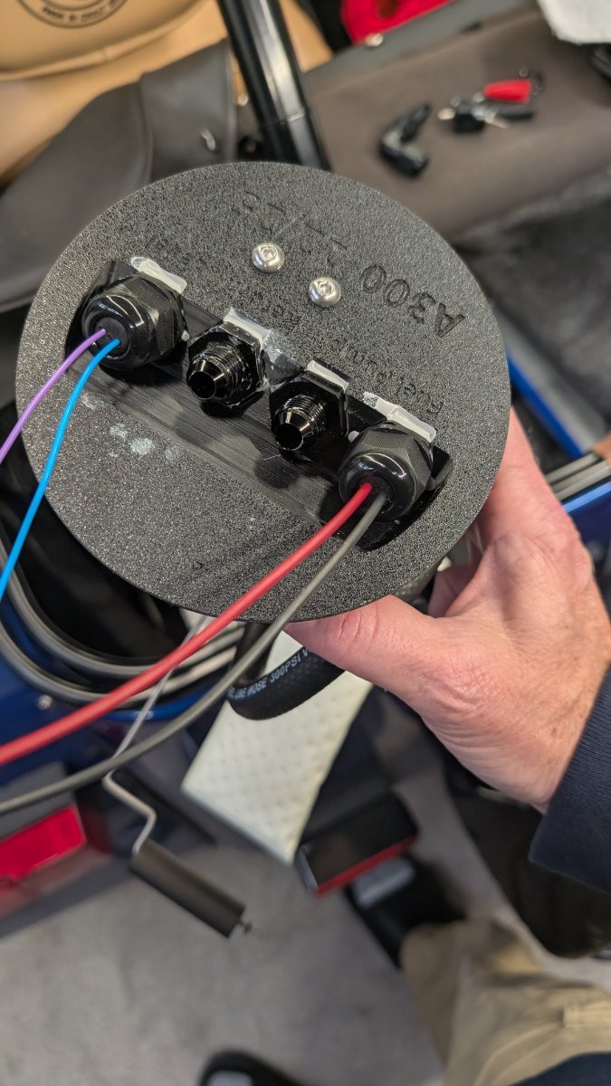
I replaced the internals in my fuel tank. The plastic hanger is replaced with a printed piece, using PCTG which is stiff and fuel-resistant. I used 1/2" aluminum bar for the standoff, and made the bright orange mount for my original level sensor / sender. The sender portion is orange because if it somehow gets loose, I want to be able to find it in the future. Both parts are PCTG, which should be very fuel / heat tolerant, and are easy to print. The lid portion is pretty thick, lots of walls. There are two bulkhead fittings for the wires, I could have done one (in retrospect). I like the symmetry tho, and won't change it unless I have another reason to reprint the mount. The through-fittings are sealed with permatext fuel gasket stuff, which I determined is extremely fuelproof. The design of the original lid holds a sort of air bubble between the fuel tank and the through fittings; I assumed this was a deliberate feature, to be sure there wasn't an obvious through fitting below the waterline when the tank is full. Because I put the sender standoff on that vertical aluminum brace, I was able to relocate it slightly futher south and can take advantage of the full swing of the sensor. Experiments pending a dry day, but at "very nearly dry" the gauge sits at the bottom, and adding 2.5g measured it reads just above 1/4.
-
- 2
-

-
Photo of your car you took today
Austin David replied to Xhilr8n's topic in General Sevens Discussion
I don't -- it's just an accidental feature of having something that will try to connect to wifi, without interfering with normal "brakelight" operation. I don't really need the wifi either, but it doesn't hurt anything and makes it a lot easier to manage without popping open a box in my trunk. -
Photo of your car you took today
Austin David replied to Xhilr8n's topic in General Sevens Discussion
Thanks! I made them, it's about 50 LEDs and a microcontroller in the boot. It's BRIGHT, with active brake/turn. The signalling is wired in to the corner lamps, and powered separately. The MCU is wifi-aware and will sync time when it's near my house. If you're serious I can write up a parts list. I have extras of a lot of it. The power draw is low enough it could run directly off the rain lamp or tail lights. -
Photo of your car you took today
Austin David replied to Xhilr8n's topic in General Sevens Discussion
I forgot I did this, but saw it last night while testing my fuel pump -- the rollbar light goes red/green for the month of December, in "running" mode. Brakes/Turn are still the normal colors.
-
some near-finished shots of the new fuel pump and hanger assembly. My return (factory pump + return line) was feeding directly down into the bottom of the fuel tank. The "standard" surge-like tank looks as if it's meant to dump return into the basin with the pump; the deadhead setup has the 90psi (?) regulator overflowing back into that tank. I suspect -- have not tried to confirm -- my return, dumping fuel into the tank and not that surge basin, led to a single low-fuel starvation event. But generally I have been frustrated with a 10g tank and maybe 7 gallons usable. Following @JohnCh lead, I mounted a Walbro 255lph pump on a hydramat. I re-used the stock sensor, see my bright orange standoff. It's mounted a little lower, and I think it will now fully sweep from F all the way down to "E" being truly empty. The lid is designed and printed; there are two bulkheads, but I could get both power and sensor wires through one without trouble. With the "custom" Al hanger, the hydramat is sitting at the very bottom of the tank, and the return is dumping right back on it as intended. I did run a wiring test with the mat almost entirely OUT, trying to drain my lines... it works as well as advertised. With only about an inch submerged it was still pulling full pressure, and the return splashing right back onto the mat and most of that getting sucked back in properly.

.jpg.4e30f6881f40fb784d2acc5462b9427a.jpg)