NVP66S
-
Posts
486 -
Joined
Content Type
Profiles
Forums
Store
Articles
Gallery
Events
Library
Everything posted by NVP66S
-
No, you're not being too picky, and I do appreciate an alternate view. I think a better solution would be to have more than 2 attach points. Maybe I'll add a glob of silicone where the fuse block sits near the frame rail. I'm not sufficiently anal to add a 3rd mounting lug with another bolt to the chassis. Doing stuff like that is how I got to have 4000 building hours on my airplane project and it's still not flying. (that project also got slowed down by my making my own post lights made of rubber for forehead smashing during a crash, designing my own bar graph EGT monitor, changing engine cooling from updraft to downdraft, etc, etc)
-
Westfield has the builder drill about 1000 (no exaggeration) 4.1 mm holes to attach the skins to the chassis, plus about 50 each 6.3 mm holes for the brake line supports, plus holes for several 6 mm Rivnuts (about 7 mm) to mount the body plus Flyin' Miata adds 8 mm rivnuts to the chassis to support the hand brake. I'm not worried about a few more 5mm rivnuts. What *would* degrade the strength would be a longitudinal slot in any tube chassis member.
-
I've also been on the lathe. The MX5 air cleaner and MAF sensor box is on the exhaust side with a long plenum runner to the throttle body. The Westfield relocates the air box to in front of the engine with some runner mods. I chose instead to use a mandrel bent aluminum elbow and some SCAT hose. But this means I need to have hose barbs for the idle air and valve cover vent. The 2 loose fittings are off to the TIG man tomorrow. Yes, machined parts are more time consuming than a simple fish mouth and fillet weld, but I wanted more fatigue strength in the welds. The big holes in the thinwall tube were super easy using a Unibit.

-
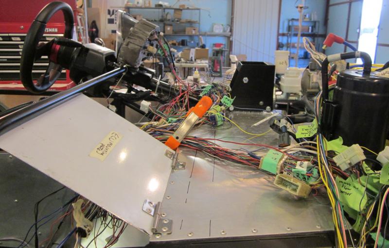
Finally off wiring and now doing metal parts. The main fuse block was just dangling when I wired it but now it has a proper bracket. Yeah I know it's a detail but the build has lots of this kind of thing. The fuse block needed to move forward and up to let the washer bottle fit.
-
Black fenders and scuttle resemble Westfield, but the chassis and body are nothing like my car. They used to offer the SEiGHT but that had a Rover (formerly Buick) engine. Where did you get the pic?
-
Here's the official answer to that frequent question/statement in the FAQs at Miata.net: http://forum.miata.net/vb/showthread.php?t=357614 Full disclosure: I bought a drivable Miata as my donor car. During the 3 days I drove it, I really came to like it. So I rationalized away buying a second one as a design template that I could follow when I had build questions. (yeah, right) Except the donor is a '97 and my daily driver is a '99 and there are many, many differences. I was driving an SLK Kompressor and traded that for the '99 Miata. I felt like I needed to take care of the Benz but I enjoy thrashing the Mazda. Now of course the question is whether I will sell the Miata when the Westie gets legal?:willy_nilly:
-
Wow. I never thought I'd see the words 'Caterham' and 'more practical' in the same sentence. :jester:
-
Thanks. Since it's appreciated, I'll do the extra work to keep the diary going. Now I'm wondering if I deleted too many things that the factory ECU will just throw up its virtual hands and give up. I'm looking at Megasquirt as a fall back plan. The second O2 sensor went first, as there is no cat pack. I was planning to keep the EGR valve and actuators (really, I was ) but it didn't fit in the space available. Ditto the charcoal can. I estimate about another week before cranking the engine. Dan
-
It's been exactly 3 months since I got my kit. At the time, I thought it was optimistic but not unreasonable to get it on the road by now. Since then, I have about 180 hours on the kit and 120 hours on the donor rebuild, mostly before the kit arrived. My logged time is hands-on only; I don't log the time spent scratching my head, reading the manuals, ordering fasteners, etc. One thing I did not plan on was the amount of wiring work. That alone is over 50 hours. Supposedly you *can* reuse the Miata looms with very little modification. I started by telling myself that I'll just modify the obvious stuff first. The audio system came out. Then the power steering, the power window wiring and the power mirrors. Then of course the heater and blower controls and the rear window defogger. Well, duh the power antenna has to go. Of course, to get at the wires you have to remove all the tape and tubing. That alone is several pounds. The pile of wire bits on the floor is growing. Then there's the fact that the ECU lives behind the passenger seat in the Miata and there are about 50 wires that go to connectors in the upper right instrument panel. Guess where the ECU is in the Westie? Yup, it's in the upper right instrument panel. So all those wires can go. The first photo shows those wires. The masking tape flags are me labeling everything according to the Mazda schematics. The second photo is after removing the unused wires (auto trans controls, power steering pump pressure, air cond controls). Big difference, huh? The next photo shows the connectors I eliminated, and the last photo is the unused pile of wire. I needed something to show for scale and it turned out I had such a thing right there. And I thought the Miata was a simple car. :jester:
-
The blue car with the square nose and the huge VW logo reminds me of John Pertwee's 'Bessie' (Doctor Who circa 1970). And is that a kit of a Morris Minor? Hmmm...
-
I'm up to 45 hours just on the wiring but the end is in sight. The Miata has 6 wire harnesses (front right, front left, instrument panel, rear, engine, and the ECU extension) and I'm making that all one loom for the Westie. A few wires get lengthened, but there's a lot of shortening going on. Not much is photogenic, so I thought I'd post a tutorial on splicing. You old hands are welcome to drop out rather than fall asleep. Splicing..... first the looong argument about soldering vs crimping. I've sat through a lot of discussions on this, both amateur (homebuilt aircraft) and professionally on real airplanes. (Plus the International Space Station that uses nickel plated copper wire instead of the silver plated or bare copper the rest of us use, but that's another story). My take on the argument is that soldering is better than crappy crimping, but solder joints need to be well restrained against fatigue and flex. The problem is that the solder wicks up the wire some uncontrolled amount and creates a flexible-to-rigid transition. But I said crappy crimping. What about good crimping? Let's leave connector back shells out of the picture for now, you can go broke buying multi-hundred dollar crimpers that are only good for one manufacturer's connectors. Wire splices..... I've been doing a lot of them. Here's a common example. The Miata has about a billion things that are backlit when you turn on the parking lights. They use red/black wire for this. In the first photo there's a Mazda splice with 5 wires. I used 3 of them. First, I cut the tape splice and threw it away. I save a short piece of wire so that there are 2 coming out of each side of the crimp connector. That's important because the crimp is designed for a range of wire sizes and too small won't grab tightly. Then, there's the crimper. A good one is important. Preferably a ratcheting mechanism to ensure the squeeze is sufficient and repeatable. I got this one (Thomas and Betts) for $30 used. Then, there's the heat shrink tubing. I get the 'adhesive lined' grade with 3:1 shrink ratio. It costs more than the more common 2:1 grade but it's worth it to get a waterproof seal. The adhesive is actually hot melt glue. Finally, the heat gun. It doesn't need to be an expensive model and I prefer one with a small nozzle. That way I can maneuver it to shoot both sides of the splice. The tubing doesn't get hot around the backside unless you rotate the wire or move the gun around the back. In the last photo, you can see the bump in the heat shrink where the short wire stub is. I apologize if all this is obvious, but I figure there are some beginners out there.
-
Was that Buttonwillow? I need to get out more, especially as Willow Springs is 20 miles.
-
A dear in the headlights? Life is too short to be serious.
-
After working 20 hours during the past 3 days, there seems to be an end to the wiring in sight. I'm checking things as I go. The horn works with the quick-release wheel, the turn signals work with symmetrical cancelling, headlights work, brake fluid level and handbrake position switches all functional. It's not very photogenic, but here's a before-and-after shot of the horn, headlight, and marker light relays. I modified the bracket from its Mazda asymmetrical mount, dressed the wires, and mounted it to the firewall. I have convoluted tubing to go over the bundles, but that won't go on until everything works.
-
Never seen one of them before likely because they're not for sale yet. Maybe it was a press car? You can see just about anything on Mulholland. There's a guy who parks his video camera there just about every week and gets some interesting stuff. He goes by rnicky mouse. Example: That's spelled r n i c k y. Clever, huh?
-
"develops 325 horsepower at 4800 RPM" reminds me of a saying when I was in high school and rode a motorcycle in 1968: "There is no substitute for cubic inches, but jumpin Jesus it hurts when you come down." Then I got back into motorcycling a few years ago and learned there is indeed a substitute for cubic inches. It's a 13,000 RPM redline and good torque the whole way there.
-
Thanks for the motivation. The wiring is not fun, lots of fiddling, and not much to show for it. When xcarguy asked me to post a build thread, I thought it would be a bother without much benefit, but the comments really are helping my motivation. I don't have photos from today's work because it's pouring down rain here in the desert and my shop is 3 miles from home and of course I rode my motorcycle to work today. Didn't want to get the camera soaked.
-
Hmmm.... I hadn't thought of that. There are already too many connectors that were needed on the Miata but not here. For example the ECU has a 6 ft cable with connectors on both ends because the ECU was behind the passenger seat whereas on the Westie the ECU is under the scuttle.
-
This thread is fully caught up with my current build status. Working on wiring is time consuming and not much to show. The Miata donor has 2 big grommets feeding wire bundles from the passenger compartment to the engine bay. I decided to make and install a pair of firewall mockups and attach them where the Westie reuses them to penetrate the scuttle. Here are the left and right sides.
-
Obviously, Manik needs to send me finders fees for all those additional sales. :jester: Seriously, I've logged 120 hours dismantling the donor car and refurbing the parts, and 160 on the build so far. This does not include manual reading, head scratching, ordering parts and tools, mulling the decision on which ECU to use, etc. WF says 120 hours, but I'm sure that refers to the complete kit not available in the US. I wouldn't have bought the complete kit anyway because I don't mind overhauling the donor bits but mostly because I'm cheap! BTW, I haven't been counting, but it seems about half the time I get a Westfield banner at the top of the page and a Stalker ad the other half.
-
Here's a photo of most of the wires not used. The bag has the loom tape and sleeving. First to go was the airbag wiring, then the headlight retractors, stereo (it was wired for headrest speakers), outside mirror motors, window lifts, etc.
-
I got the kit in February and this thread is pretty much caught up to my present status. I'm in wiring hell at the moment. The Mazda donor version of the WF uses the Miata wiring looms. For a simple car like the Miata, it sure has a lot of wire.
-
Next mounted the fan and radiator. The fan is from the Miata and the radiator is new supplied as part of the kit. We temporarily lowered the body in place. Looks more like a real car, but it had to come off again. This was about 2 weeks ago.
-

usa7's meet in Carlisle PA next year?
NVP66S replied to RGTorque's topic in General Sevens Discussion
My day job had me out of town for a week, so I'm gonna use that as the excuse why I can't get my project on the road by then. Heck.