Christopher smith
-
Posts
267 -
Joined
-
Last visited
Content Type
Profiles
Forums
Store
Articles
Gallery
Events
Library
Everything posted by Christopher smith
-
MV8----Thanks for your valuable info to solve my "Saab Story". Still wondering how I had it working fine in the same exact configuration for years, albeit light usage except some really fun test laps at NJMP. I guess I will still try to get the last of the air out somehow ( reverse bleed?) before I take the next dreaded steps of pulling the engine again to get at the plumbing.
-
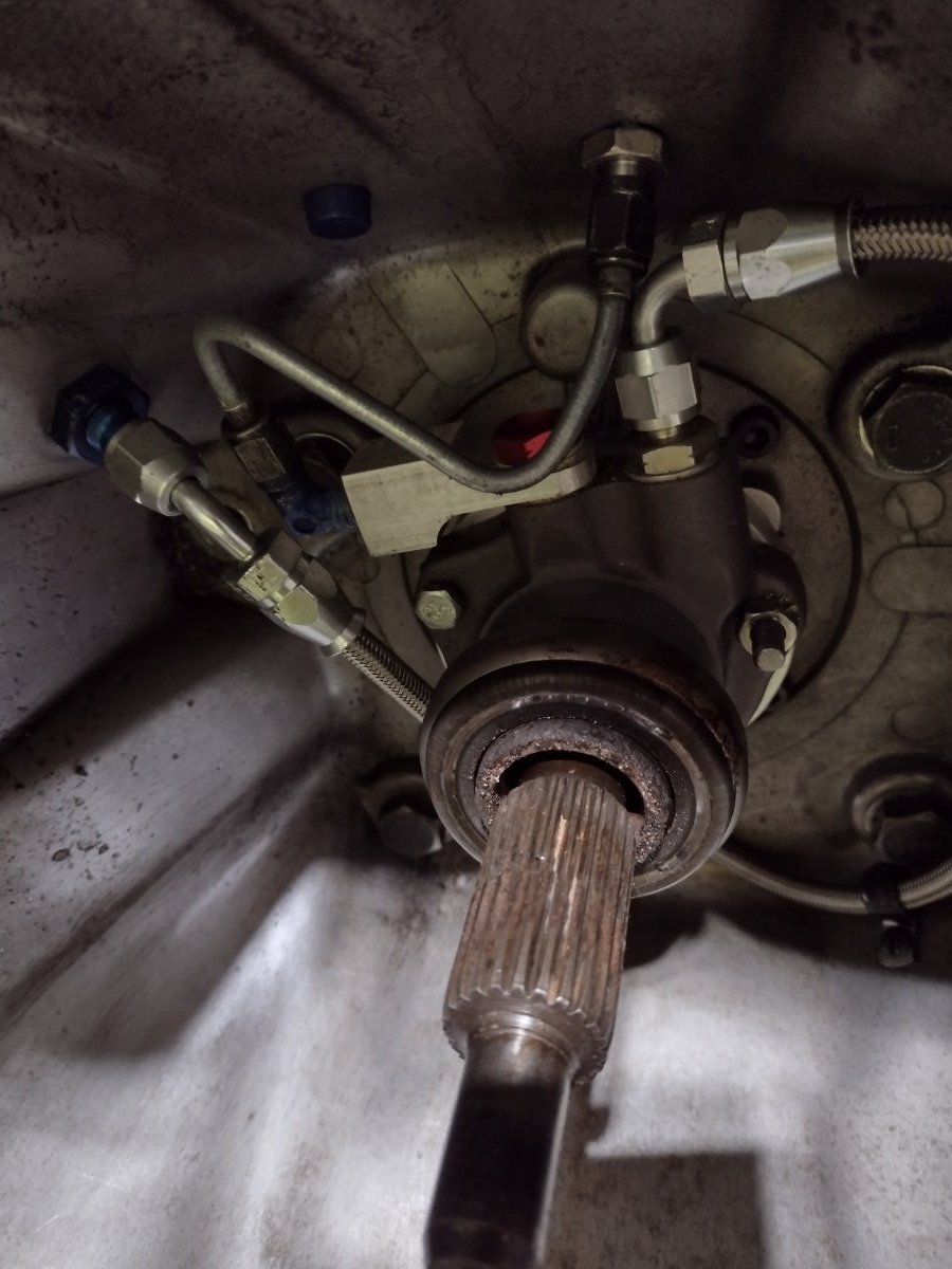
Many thanks. I think I may not have done the bleeding thoroughly since the plumbing had to take a circuitous route in the original install and my engineering friend has passed away since. Probably not as bad as the rear engined race car he did. I made various attempts at the old 2 person method and tried vacuum bleeding from the remote bleeder and also pressure bleeding at the master cylinder. All of those methods exited at the remote bleeder so flow was long downward before 2 upward runs and I guess that trapped bubbles. I am thinking of back flow bleeding if I can set up for it. I have attached an image of the old slave cylinder that had leaked but worked fine for some years after a conventional 2 person (pedal pump) bleed, so I guess I am doing it wrong. Still wondering about the mechanism that could explain why the clutch actuation is fine for 5-7 starts and then not.releasing.Could air in the line do that on heating maybe? I should have stayed awake in my thermodynamics P chem class. Sure appreciate your guys thoughts.

-
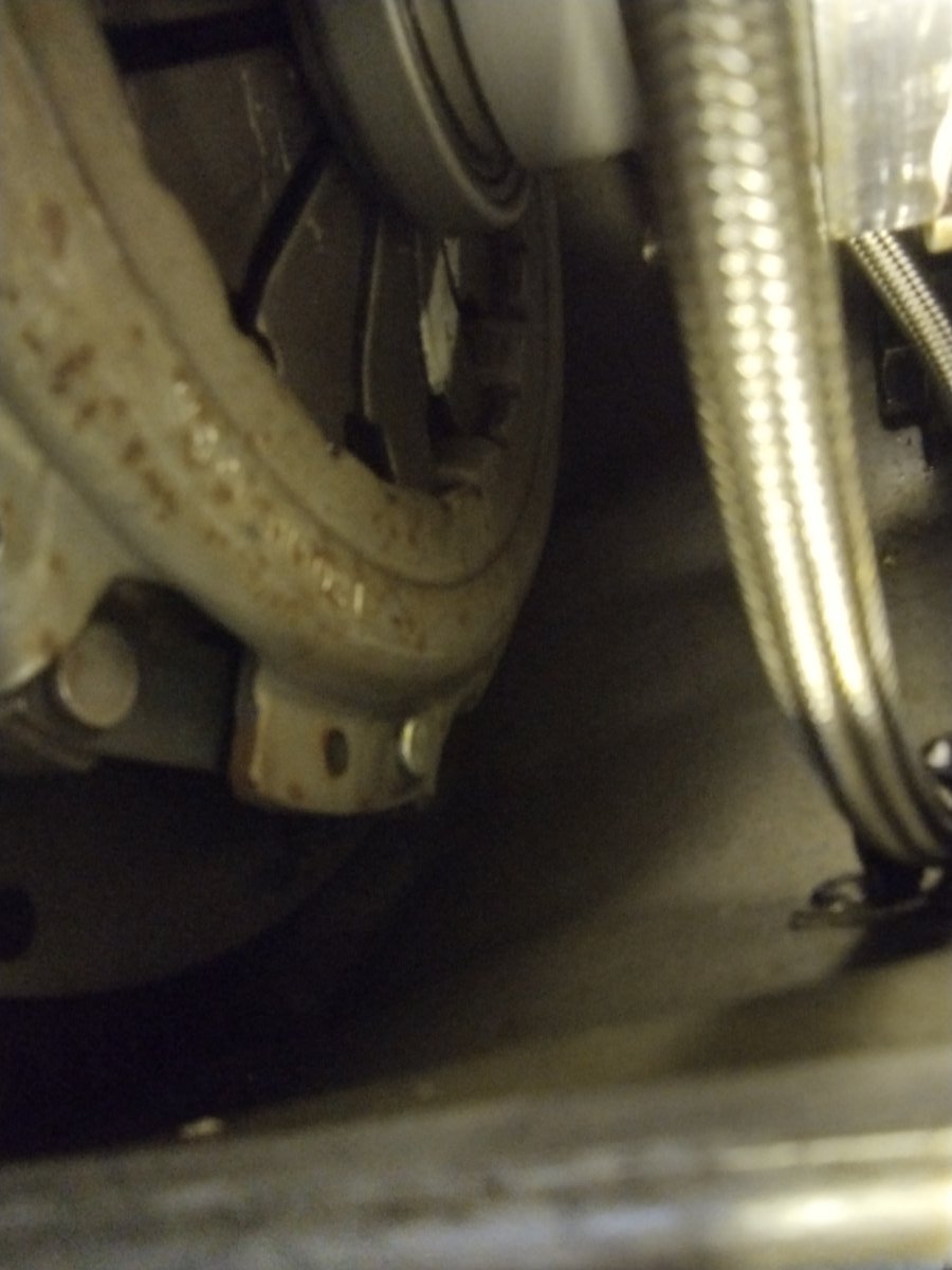
Clutch action was fine for 5 years of light use, but concentric slave cylinder finally started leaking. It is a Saab 93 type slave set-up (from Bean Engineering) coupling my 1500 pre-crossflow to a pinto 4 speed using a Tilton pedal and master cylinder set-up with -4 Earl's lines in my tight clearance 1959 series 1 frame. So I had to pull the engine to get at it but not the trans, to replace the concentric slave cylinder and I replaced the master as well. The clutch works fine as I test it up and down my driveway about 5-6 starts. Then I get a frightening grinding sound trying to put it in any gear with pedal fully depressed at a stop. I have adjusted the pedal stop back and forth to no avail. Reaching in through the old side port in the bellhousing I can see the release bearing and it just touches the pressure plate fingers, but I can rotate the release bearing with my finger. The bell housing seems warm but not sure why it would work fine for years and then when replaced, work fine at first and then fail to release after a few start-stops in the driveway. If you click on the image you can see the release bearing. Any thoughts or ideas most appreciated, particularly if I do not have to pull the engine a 3rd time.
-
Anyone have advice for a foot rest design? Really tight footwell on my 1959 series 1 even with my size 9 shoe. With RHD my foot is within a few mm of touching the trans tunnel when on the clutch pedal. I can work the pedal OK on this Tilton hanging pedal assembly. So maybe rivet or bolt a small metal angle piece to the floor just aft of the unpressed clutch pedal? What does Caterham use-approximate dimensions and location relative to the clutch pedal?
-
They meant to say Dartford not Darford. Looks like spellcheck struck again.
-
collapsible steering column for 7 S2?
Christopher smith replied to Timothy Keith-Lucas's topic in General Tech
There were several changes from a series 1 like mine to a series 2. Not sure why the changes were made as I do not think the total weight dropped. The steering rack was farther back , behind the axle. The column has 2 universal joints with one at the rack and another about 1/2 way back to the steering wheel. Not sure if that makes a difference in a major crash. The rear suspension had 2 outer links on each side of the axle rather than the central pick-up and I assume that was when the cracked housing issue started, or was it better traction tires that caused the cracking? I assume the couple of diagonal frame tubes by the driver and passenger knees were removed to save weight but could not have been much. Any explanations that make sense? -
Just a thought- Some of the books list the axle on series 1 as BMC Nash Metropolitan which is virtually the same as Sprite and the A40 I have so you may want to show that as a choice since some may not have been sourced as A40. Thanks for the efforts!
-
My series 1 #475 still has the original 4.22 to 1 axle that was from an Austin A40 that had the suspension attachments done at the Lotus factory ( I have the receipt for the work- really cheap back in 1959!). It is the same as an early bugeye Sprite and Nash Metropolitan and these were used for quite a few series 1 cars from what I understand. Probably lighter than the newer variations and the suspension does not attach under the center like series 2 (that apparently is a major failure point if highly loaded). I do not have LSD or the double bearing modification that many racing Sprites used.
-
Air filters on a pair of DCOE 40 Webers
Christopher smith replied to Stevensonjr's topic in General Tech
I looked around for info and see that some makers of mesh caps claim 2 or 3 layers of stainless mesh with what may be a paper filter layer sandwiched in between layers to trap finer particles. They claim no restriction but I find that hard to believe. I also went to the McMaster Carr website to see their offerings of mesh which gives nice detailed info on wire size, wire configuration and a calculated open area for quite a variety of mesh offerings. When I can get to it I will measure the actual ID of my velocity stacks inboard of the wider area where the mesh caps attach to calculate area and compare that to the somewhat larger area of the mesh and add that to the extra area provided by the mesh side openings since the mesh is "belled out" a bit. I can then put a micrometer on the wire and maybe count the wires per area to calculate open area to compare with the smallest cross section area inside the velocity stack. Probably a waste of time but now I am curious. it would be great to see dynamometer data if anyone has it as that is the real test and sorts out any peculiar aerodynamic effects within the ports as well as within the carb throat and the stacks and a filter or mesh screen. -
Air filters on a pair of DCOE 40 Webers
Christopher smith replied to Stevensonjr's topic in General Tech
I guess the reduced throughput of a screen is the reason why the ones for velocity stacks always are always rounded out to give more surface area. Maybe not enough however. Not sure -
Air filters on a pair of DCOE 40 Webers
Christopher smith replied to Stevensonjr's topic in General Tech
Does anyone have any dynamometer or other actual flow data on the stainless mesh or for that matter any air cleaner types? What were the cars out front for all those years in D Production using for their 1340 and 1500 cc powered pre-crossflow cars? -
Air filters on a pair of DCOE 40 Webers
Christopher smith replied to Stevensonjr's topic in General Tech
I recall hearing that the short velocity stacks are optimum for high rpm while tall ones are more for torque at lower RPM.Not sure if this really matters much. -
Air filters on a pair of DCOE 40 Webers
Christopher smith replied to Stevensonjr's topic in General Tech
I have the stainless steel mesh type on my 40 DCOE2 velocity stacks. Not sure they filter out much except nuts,bolts and stones. And the rubber attachment rings seem a bit shaky. So can not recommend this type for higher mileage use particularly in dusty situations. But I see claims of better performance from other mesh air horn units. I recall seeing the oval track sprint car guys running without any filters or mesh and wondered how many rebuilds per season they must do. -
Craig- I followed the old Vizard book for substantial combustion chamber modifications and ports on my Cortina GT sourced 1500 pre-crossflow. I was curious how the Cosworth motors differed from this when supplied back in the 1960s Super 7s. Was the Cosworth approach very different from stock Cortina GT? hanks-Just curious
-
It has been many years since I was there but I think I stayed in Bologna and commuted by train to Imola. I walked a lot around the track and for the race I was on a hill on the outside of the track that overlooked the last couple of turns before the pit straight. Pretty crowded. Not sure you can still do that on a general admission ticket but worth checking. Train service is great in Italy unless you get off at the wrong stop in Monza like I did a few years ago. I should have just followed the crowd. Have a great time!
-
Some of the Ferraris in "Ferrari" were Caterhams
Christopher smith replied to Nick OTeen's topic in General Sevens Discussion
I enjoyed the movie and the way the cars sounded- not sure how they did that but the originals were some naturally aspirated 4 cyl and some v12s so somehow they got great sounds spliced in. Do watch for the downshift to go faster on a straight section and probably more side by side racing than really happened, but otherwise OK. I would also really recommend finding the movie "Ferrari -race to immortality". In this 2017 full length documentary type movie they have many great clips from the original GP and pro level sports car races from late 1950s just before most went rear engined. Of course there were lots of tragic crashes back then and the movie did interview some of the drivers pre-crash and relatives and other drivers post crash. No Hollywood plots or fake stuff but somehow great photography preserved (enhanced?). -
Great work!
-
1964 Lotus Super Seven Engine Questions
Christopher smith replied to TEM's topic in General Sevens Discussion
MV8's comment about the wobble allen is spot on at least for initial tightening. I was worried it might round off in final tightening however, and that is when I cut off part of the short end of a conventional allen to allow final tightening. Also, someone before me installed a 2 ended stud at one point in the head which allows for holding the gasket in place easier. It then takes a 12 point flange nut ( McMaster-Carr sourced) to clamp the full assembly down. I managed to refit the whole intake + 2x40 DCOE assembly at once but that may be trickier than first fitting the headers, then intakes and then adding the carbs and finally linkage. I never had a manual so it took a lot of guesswork to figure it out. Now with access to a manual for series 2 I will look and see the "professional" way to do it. -
1964 Lotus Super Seven Engine Questions
Christopher smith replied to TEM's topic in General Sevens Discussion
Happy to help with some ideas just contact me when you're ready. I have been through it several times -
1964 Lotus Super Seven Engine Questions
Christopher smith replied to TEM's topic in General Sevens Discussion
For sure It is very easy to get it wrong, so you will want to be sure you note the location of the correct bolt types. The assembly sequence is also tricky since you may not be able to start the top bolt threads unless the manifold and header flange are a few mm away from the cylinder head. Or at least that was my experience. I found that cutting an allen wrench to shorten it a bit was the only way I could get at a couple of the bolts ( some by reaching from below). The Cosworth guys were geniuses for sure, but it was still tricky. -
1964 Lotus Super Seven Engine Questions
Christopher smith replied to TEM's topic in General Sevens Discussion
Looks a lot like my 1500 5 main bearing type. Mine is early Cortina GT based ( rope seal type). 120E6015 now with a 2x40DCOE that looks similar except the intake is a welded fabrication instead of a casting.Looks like we all have similar fun with the correct special bolts and install sequence with those clamping the intake and header flanges. -
1964 Lotus Super Seven Engine Questions
Christopher smith replied to TEM's topic in General Sevens Discussion
good advice you are getting. Not sure why the 1500cc type 116E head is on a 1340cc block but assume it fits. And yes- be gentle with that 3 main bearing engine. The mark on a normal 116E timing cover is for 10 degrees BTDC according to my Cortina shop manual. -
New article posted - British Motor Museum and Goodwood
Christopher smith replied to Croc's topic in General Sevens Discussion
Great stuff! I particularly enjoyed the video and analysis of track day in the rain at Goodwood. I recall racing in the rain with my full wets beside a few other low budget guys who still had their slicks on at a Pocono SCCA regional a long time ago. For anyone planning a trip to the UK I hope they get a chance to go to Goodwood for the Revival. While not as exciting as driving the track it is a great experience I had 2x. -
If I recall correctly, the FP class was limited to 948 expanded slightly with 0.040 inch maximum overbore. If all previous owners complied with the rules back when it was raced, it should have complied but pulling the head is the only sure way to know. I raced against them in my FP class Sunbeam Alpine that was 1725 + 0.040 over bore. They always outcornered me but lost on the longer straight sections.
-
Unfortunate incident. Perhaps some of the parts now deserve crack inspection with at least penetrant dye kit? Lucky that many 7 parts are from cars with almost 2x the weight so usually pretty sturdy. But still might be good to check as the parts were not designed for big impact loads. Having a front spindle snap on a street driven MGTC at 5 mph sold me on crack testing. The hidden crack looked to be over 50% of the cross section.