copy.jpg.dd4bdbb41ccb3ea8a585d1ad217ef61b.jpg)
.jpg.da03509438cc84820b8cf5d64db570ab.jpg)
Austin David
-
Posts
391 -
Joined
-
Last visited
Content Type
Profiles
Forums
Store
Articles
Gallery
Events
Library
Everything posted by Austin David
-
.thumb.jpg.885191d302e6c3704c848a8f5ac3a612.jpg) To be abundantly clear, what I'm looking for here is some experience with the "normal" process (which appears to be a kafkian maze of bureaucrats who don't understand, or creatively interpret, the rules) -or- trying to find a professionally-managed, legit service who can help. The last thing I want or need is a registration that will cause more grief. But holy heck is it ever frustrating. My wife joked that she thought the hard part would be *building* the car.... Also FYI: 401-A is apparently needed because the vehicle doesn't exist in the state and needs a serial number. I'm unclear on how that interacts with the VIN. I moved 2 from Cali and it was NOTHING like this process. 4038 is needed also, possibly *before* 401-A, to confirm that the vehicle does, in fact, exist. In CA this can be a cop signing the paperwork in your driveway, hopefully I won't have to trailer the vehicle across town just to have someone look at it. But 400 doesn't indicate the need for 401-A., and 401-A doesn't indicate the need for 4038. ... I do appreciate everyone's experience and perspective. Thank you!
To be abundantly clear, what I'm looking for here is some experience with the "normal" process (which appears to be a kafkian maze of bureaucrats who don't understand, or creatively interpret, the rules) -or- trying to find a professionally-managed, legit service who can help. The last thing I want or need is a registration that will cause more grief. But holy heck is it ever frustrating. My wife joked that she thought the hard part would be *building* the car.... Also FYI: 401-A is apparently needed because the vehicle doesn't exist in the state and needs a serial number. I'm unclear on how that interacts with the VIN. I moved 2 from Cali and it was NOTHING like this process. 4038 is needed also, possibly *before* 401-A, to confirm that the vehicle does, in fact, exist. In CA this can be a cop signing the paperwork in your driveway, hopefully I won't have to trailer the vehicle across town just to have someone look at it. But 400 doesn't indicate the need for 401-A., and 401-A doesn't indicate the need for 4038. ... I do appreciate everyone's experience and perspective. Thank you! -
SC is super slack, generally. Trailers don't need license plates at all, no emissions testing or requirements, etc. I even sign a form saying I'm responsible for the vehicle being road-worthy. But that bit about "intelligent, caring people across the desk" kinda lost me ... haha. Something about that desk seems to change people. Great point about insurance co shenanigans. I'll check on that. Right now my plan of attack is #1 find $1k under a rock somewhere, and #2 do the thing, then with out-of-state plate+title+reg in hand, proceed to "import" the vehicle to SC before my year is up. I'm still gonna poke around to see if there's a sub-$1k option.
-
Hi everyone- I'm still one-sided-struggling with SC DMV. I can't penetrate the system, but I've "only" been trying for ~ 6 weeks. While working that on the side, I found dirtlegal.com and called them, plus googled around a little. Has anyone used that service? Alternately does anyone know a good way to exchange $cash for reasonably certain plates so I can get on the road? $699 (ish) and 2-4 weeks gets a South Dakota plate; SD doesn't have a residency requirement. $199 and 1-2 *days* gets a 90-day temp tag $299 up front, 119/yr after gets an LLC registered in SD which can own the car and work around a state's curiosity about an out-of-state plate living at your house. SC claims to care after 45 days, it's unclear if that's "enforced." Finding out may cost a misdemeanor and $75. .... and I believe / assume that after I have SD plates I could "move" the car to SC for year 2, mod any impact fees or duplicate taxation. The Internet(tm) seems to think dirtlegal.com is legit, if a little weird. Anyone have direct experience? (for completeness I have talked to the DMV, the local tax office, my own insurance company, and Hagerty's; they're all approximately equally useful, and I got a 3 different answers and a couple "I can't help you"s).
-
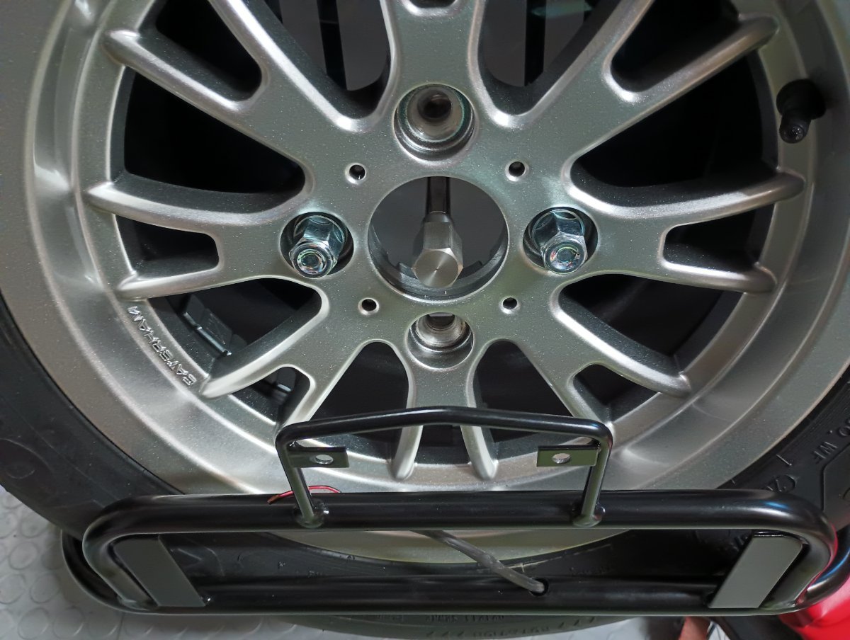
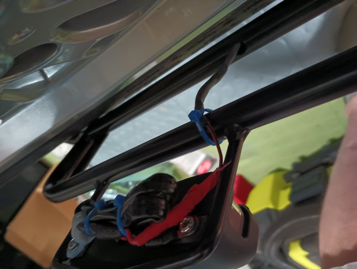
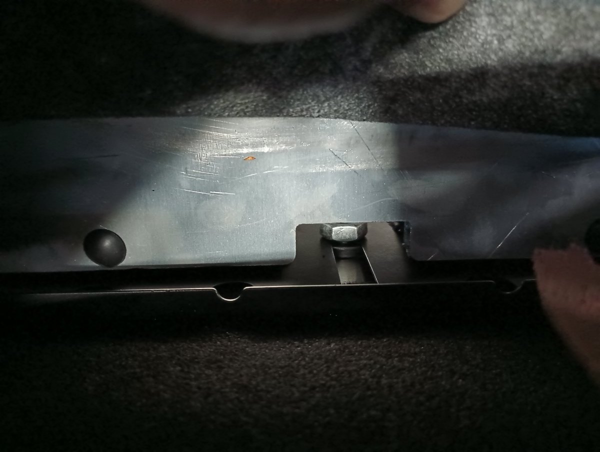
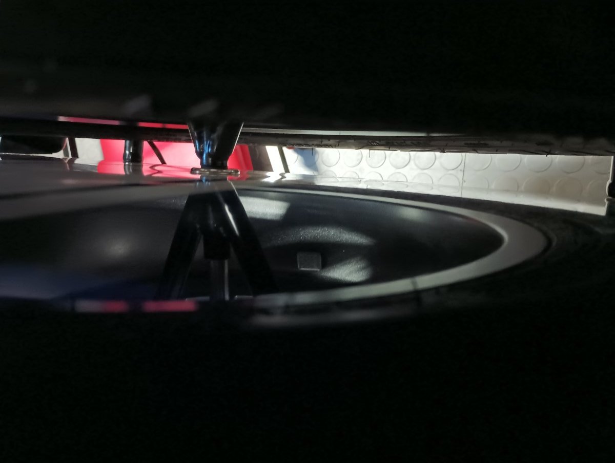
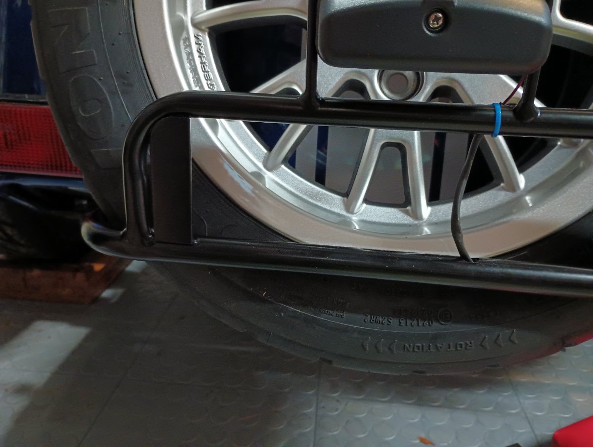
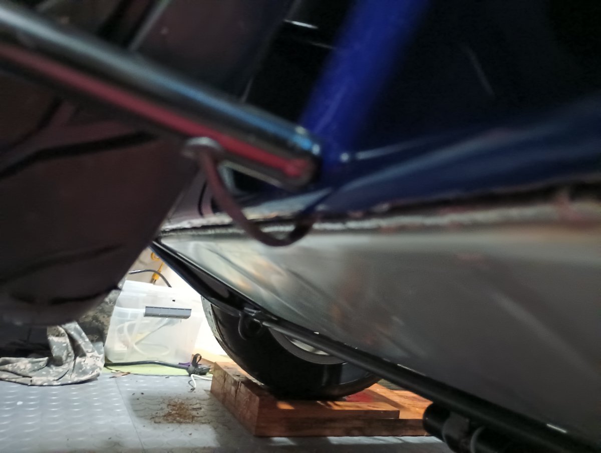
Spare tire carrier -- I haven't found any builds with this, had to puzzle through it but I got there. There's the carrier, a wishbone, two extra lugnuts, a fancy long bolt + LONG spacer, and a separate pack with two unused bolts, a shorter spacer (about 3"), and a fibre washer. Plus the license plate light, which I assume is common across all kits. 1) the carrier itself mounts directly to the frame. The license plate wire (black/red) was zip-tied to one of the mounting holes. Cut that loose, then bolt up the carrier. Two 13mm nuts can be tightened from underneath, open-end wrench only. 2) there's a nut behind the fuel tank, inside the skin. You can access it from the boot / under the carpet, but I didn't have a large enough open-end wrench to secure it; it's bigger than 21mm. Adjustable didn't fit. I used pliers to hold it still, and ran the long securing bolt + oversize spacer to spin the bolt-side from outside. This bolt secures the tire hold-down to the frame, through the aluminium skin, so I assume it's pretty important. 3) the 5th tyre: mount the wishbone w/ 2 extra lugs, run the fancy bolt + shorter spacer into the wishbone, then CAREFULLY set the wheel in the carrier. Add the fibre washer, then the bolt can pass into the mount on the body. Snug up the bolt, then use a lug wrench to snug the two lugnuts (securing the wheel to the wishbone), then tighten up the longer bolt to secure the wishbone to the body. I didn't crush this down, just don't want anything rattling loose. Most of the weight is borne by the carrier, but this wishbone assembly keeps the tire from rolling loose or rubbing on the body. When it's all done I have about 1" clearance to the paint, tire resting on the carrier. Still plenty of room to install the plate and light. 4) the light has a single red/black wire tucked under the frame, and plenty of slack. It's got a plastic sleeve already there. There's a grommet on the RHS of the carrier. Feed the wire into that grommet, and it will easily snake its way through the frame to the back. There's a roomy hole in the top of the frame, behind where the plate will eventually go. I was able to fish the wire out with tweezers, there's room for needle nose. 5) the light came with a ton of wire, I just tied all that up. A ring terminal on the black wire / light side, and a spade between the red and the red/black from chassis. I added heat shrink and tape, this is all exposed to the elements. Sand off the RHS mounting hole a little, that's our ground. Remove the cover for the light (single screw). Terminal goes there, bolt through the terminal from the back, then the nut on. Connect the reds, test. 6) for cleanup, I added a nylon wire clip on the LHS mounting bolt to hold that bundle of wire. Zip ties to keep it tidy. The worst of all this is that the hot wire comes up from the bottom of the frame, but it will be pretty well obscured behind the license plate, eventually.

-
Ahhh.…. That sounds like mine. They FIT as long as you're not too picky about the holes lining up. I haven't drilled mine out yet. Honestly I think our experience is similar. I spent several days with the diff trying to see how to get it in there. Good times. By now I'm mostly waiting on the DMV.
-
Josh confirmed picking issue; the outers should both be glossy plastic. The inner (rearview) is matte too, but not as bad as the ginormous plastic windscreen mirrors.
-
Mirrors: terrible. Per instructions you have to remove the mounting screw to remove the mirror post. WHAT THEY DON'T WANT YOU TO KNOW: that screw holds down a metal cup, spring, washer, and backing nut. Once you let that go, they're all loose inside the mirror housing. Press out the glass, reassemble the stuff to the new mirror post, then hop online and look for better mirrors. I'm in that step right now. I think 4" round chrome would look good, complement the headlights. If that fails I'll reassemble the mirrors and use them until I find something better. My aeroscreen mirrors are much nicer, but they don't match. Asking about that now. LHS is carbon (nothing on my car is carbon), RHS is shiney black.
-
Wait, your knee plates fit? How much bending did you do? Are they tucked under the dash, or hanging out?
-
So, tell us a little about yourselves
Austin David replied to slngsht's topic in General Sevens Discussion
Whoa. Looking forward to more photos in a week or so! -
That sounds exactly like what Josh relayed. How did you screw them on? I think he said bolts through the top into the stay, with stainless + neoprene washers? I'm planning to use 3M 5200, which is generally considered "don't use this unless you never ever want to remove it". The fast cure version only comes in white tho, so I'll either top it with slower-curing black, or (and?) will undercoat the fender. It's already painted, acetone took up some of the paint when I was prepping for the adhesion.
-
Tool kit, for touring / far-from-home? (Caterham)
Austin David replied to Austin David's topic in General Tech
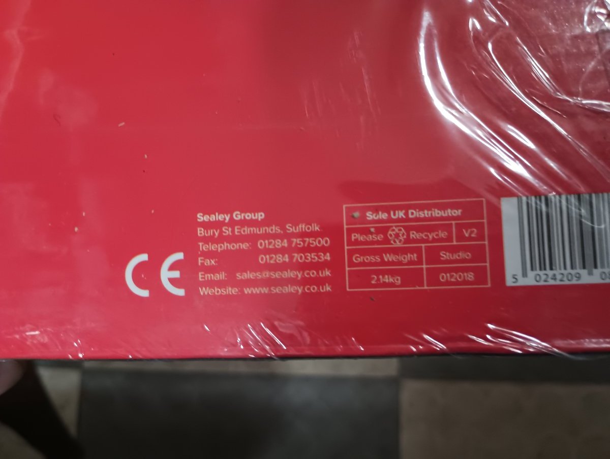
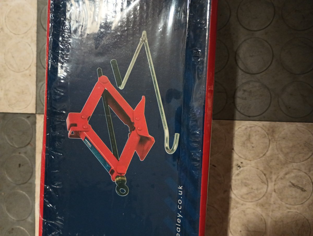
My kit came with this: looks like (and feels like) about 2kg. I also just printed a c-spanner which weighs approximately nothing and so far works well. Happy to send some around if anyone has Bilsteins... or with some photos and measurements, probably just make a specific one.
-
Tool kit, for touring / far-from-home? (Caterham)
Austin David replied to Austin David's topic in General Tech
fair. I'm specifically after the newer Bilsteins, which have 6mm holes. My VMAXX spanners don't fit. -
Toe is adjusted by rotating the steering rods (which AFAIK is very standard). The flats are hiding under the boots -- nip the installed zip tie, push the boot back, there's room for an 11mm wrench. But not a lot of room, my stubby did fine. The boots don't move *except* when adjusting toe. One of mine was kinda sticky so I put some grease on the flat and slid it forward/back, then finished the adjustment. There's a groove (past the flat) where they sit while tied. Apparently for track cars, or any application where you're making several adjustments per day, it's a thing to just not re-apply the ziptie.
-
Tool kit, for touring / far-from-home? (Caterham)
Austin David replied to Austin David's topic in General Tech
Any recommendations for the C-spanner (or whatever it's called) for adjusting the coilovers? -
Fender blinkers, ya. I'm splicing the ground through, and the first time I have to remove it, I'm gonna splice the signal wire too. Sleeved all the way and the terminals tuck into the stay just fine. Esp if it's not molested with a ground screw.
-
How do you wire the indicator lights? The book has them grounded to the wingstay, and the hot/signal wire snaked through and tied across the wishbone. Did you splice in a disconnect? Or are you not using it at all, because racecar?
-
I have the fibreglass / painted wings, a LOT of texture on the bottom. I'm actually spending more time lining the wires to pass through the stay. Looks like I'll be able to start glueing this evening.
-
Thanks (again) -- so that's gonna be something like (p136-141 in the 2.1 Ikea book): - prep the stay w/ 100# sandpaper + acetone - layer of adhesive on top of the stays - tape the wing down, wait 24h - remove the wheel, add MORE adhesive at the sides of the stay, full length under the wing - let it cure more
-
What's the prevailing wisdom here? I've seen a few concerns about sika pulling off on racetracks and I've heard an anecdote about road use in Utah, possibly caused by HUGE temperature swings. 2015 book seems to want them screwed to the wingstays, Ikea 2.0 clearly says to use the powerglue / Sika stuff. I'm a 5200 fan myself. How aggressively should I attempt to fix these things, for road use?
-
Not at all stupid! I had already played "boot carpet tetris" so I was prepared for two similar-looking-but-not-identical parts. Without the carpet they were *perfect*. With the carpet they're a little too wide -- exactly one carpet-depth too wide. NBD, just funny. I assume they make one size of mat, and not everyone gets carpet. I put the seats in today and see that the frame member is under the seat, so that rubber mat entirely consumes the actual footwell. Clever design. Also I've officially upgraded from "noisy collection of parts" to "noisy loveseat."
-
Tunnel carpets are in. This is a standard S3; there's a frame member across the floor. The floormats are cut to JUST fit in the trapezoid between the tunnel, front of footwell, side, and that frame member (about under one's knees). Unfortunately the carpet also comes down to the floor, which makes the floormats too big (or the carpets too long). For now they're folded up a little at the sides, I'll hold off a bit before cutting anything.
-
Carpet: apparently I ordered "more carpet." There's a biggish panel for behind the seats, not listed in the Ikea 2.0 manual. In 2015 it's the "rear bulkhead carpet" or "seatback carpet" (p145). I used thin carpet tape, not glue. Had to unscrew 6 "poppers" holding the boot cover, tape this big panel to the back face of the cockpit. It will need some trim around the belts (I have 3-point / retractable). The top edge of this section is matching vinyl. I pulled that into the boot area, held it snug, and folded the two outside corners over. This exposed the screwholes for the two outside poppers, which I used to fix the position of the boot cover. With that in place I was able to seat the center 4 poppers through this vinyl flap. One at a time, holding it nice and snug, and already centered with the tunnel, the seatbelts, and secured (a little) with carpet tape. The screws are pointy enough that they went right through the vinyl, no issues. I've also got a whole tangram set for the rear boot. I've puzzled that out (pun) and I think every piece will need to be trimmed. Have not yet decided if I will actually apply every piece. Josh (RMC) recommended the carpet tape, I love it. It sticks to the bulkhead or boot floor, and holds the carpet BUT is also easy to reposition. Edit: the seats pretty effectively block the belts and where they interfere with the carpet / feed into the retractor. If you want to trim, do it before installing the seats. Also it may not be obvious for the less-initiated, but the seats take up every bit of available space -- do them last. Kinda like the transmission and duratec (at least in S3): the car is essentially the bare minimum, snugged around a transmission, motor, and two seats. They touch the carpet on both sides, effectively block the harness attachments, and press the buckle against the cutout in the tunnel. I've taken to telling people it's basically a kayak.
-
Yeah, I lived out there for 15 years. I don't miss the 2-hour commute, but I definitely miss the weather and the roads.
-
ok mr KnifeySpooney I will straight up buy you a burger at Alice's, if you drive. And fries and stuff. tl;dr the sender was wired backward. Read on for some data. I tried running a dedicated ground to the sender wire (submarine chassis / screw terminal) and the temp gauge shot UP. Which is nuts, right? The original wiring (as I assembled it a week-ish ago) was with the loom single green wire -> submarine chassis, and loom two black/yellow -> sender center. So I flipped it and the temp read more like I expect: slightly above 100C (indicated) when the fan kicks in, drops slightly below 100C (indicated) when the fan finished. While I was over there I also took ohmeter readings for a few fan cycles. It was very consistent. The fan consistently led the temperature / resistance swings (that is, the submarine reading trailed the ECU behavior and fan cooling) so I assume the internal temp reader is up front / upstream, cooling action is upstream, and the submarine sees cooler water about 10 (ISH) seconds late. Fan kicks in at 134 ohms, the reading drops as low as 131 before it starts rising. Higher reading == lower temperature. I haven't found a good table for this sensor; autometer's article says 210F (100C) is 123 ohms, so maybe this was south of that a little? Fan cuts off at 136.5 ohms, and resistance rises as much as 144 (cooled fluid circulates to the submarine) before it starts falling again as the cycle repeats. I observed this several times very consistently. About the sender: I just again scoured the 2015 and v2 Ikea manual and can't see where the wiring is mentioned. I must've incorrectly ASSUMEd the single green wire was the earth and the two colored wires were the signal. I further assumed it didn't materially matter, since it's a resistor and not itself connected directly to the chassis ground. ¯\_(ツ)_/¯ I put it back to the "original" connection and confirmed it was as before (reading ~ 110C). The "other" way has it reading more inline with expectations at 100C when the fan cycles. Anyway, that article got me to first double-check the ground which pointed out the wiring issue. Onion rings on me (eventually)
-
Confirmed my temp sender+gauge reads about ~15C high, using an external IR sensor against the water rail, block, and hoses at the submarine. Fan cycles correctly (kicks in around 95C external read on the water rail). Hopefully I can calibrate the gauge, but failing that it's either a new sensor or some shenanigans with a trimpot.