

Pokey
-
Posts
410 -
Joined
Content Type
Profiles
Forums
Store
Articles
Gallery
Events
Library
Everything posted by Pokey
-
My guess to the starter, on its way to the battery.
-
Zetec and Caterham 6-speed hydraulic release bearing (slave cylinder)
Pokey replied to Pokey's topic in General Tech
For posterity, the combination Zetec with the Caterham 6-speed seems to work with these hydraulic release bearings (slave): Ford F5RZ7A508BA, F5RZ7A508BB, 94ZT7A564BA, 94ZT7A564BB Sachs SB60093 Sachs 3182 654 208 AMS Automotive N1767SA LuK 510 0067 770 LuK LSC273 Perfection Clutch 360062 I can personally vouch for the Sachs 3182 654 208 and the Perfection Clutch 360062. The others should work but beware of one possible caveat in differences in the casting where the nipples are located. I've seen some derivations that look to expect to have the top of the slave protrude out the opening in the bell housing which only works if the slave is aligned with the hole. -
Zetec and Caterham 6-speed hydraulic release bearing (slave cylinder)
Pokey replied to Pokey's topic in General Tech
Thanks @CarlB, same here, I didn't use a LUK-273 but the equivalent. I've installed a pedal stop and a new slave cylinder and all seems to be working as it should. -
Zetec and Caterham 6-speed hydraulic release bearing (slave cylinder)
Pokey replied to Pokey's topic in General Tech
Thanks @MV8. Sounds like you agree that the pedal stroke increasing could account for the failure then? BTW, I bled using suction from the slave’s bleed screw after assembly. -
Long story short, hydraulic fluid dumped from the slave onto the bottom of the bell housing. We replaced the slave, bled, and the same thing happened. The original slave's manufacturer is unknown, but the replacement was a Perfection Clutch 360062. The two look identical down to the first four digits of the number stenciled on the casting as shown in the picture below. The release bearing touches the clutch's fingers but does not look to be depressing them. When the clutch pedal is operated the release bearing does not move. That's the facts, now comes the random thoughts: I took the clutch off to inspect, and while it seems unlikely I installed the clutch disc backwards, and unlikely that I could have cinched down the pressure plate had I done so, and it isn't clear how doing so would cause the fingers to become unmovable, if the fingers were stuck in position then what could have happened is the slave cylinder seals failed as the hydraulic fluid had to go somewhere. Note that this thought does not explain why the original slave failed in seemingly the same manner. The clutch pedal does not have a stop, or more precisely the stop appears to be the bulkhead, which over the yeas has deformed outward by a centimeter or more. Assuming the master cylinder can move more hydraulic fluid than the slave can accommodate, and that the pedal-induced bulkhead bulging allows more pedal movement and hence more fluid leaving the master, then, again, the slave cylinder's seals would suffer as a result. This would also explain why the original slave failed, but it also requires that while bleeding the clutch I pressed down to where the pedal pushed on the bulkhead. I can't say that I did or did not as I wasn't paying attention. Operating the pedal now using only half of the pedal stroke still results in hydraulic fluid transfer onto the floor of the bell housing, so that either means the clutch fingers are immovable or the slave's seals are so utterly destroyed that the resulting pressure isn't enough to move release bearing against the fingers. Anyone every experience anything like this? And those with a Zetec/6-speed setup, do you happen to know what slave you have installed?

-
Not sure if I posted anything at the time, but I had one cylinder running colder that I eventually traced back to the ignition signal coming from the ECU. For me the symptoms were more binary than for you, all of a sudden I (partially) dropped one cylinder. Granted, symptoms were more or less acute depending on driving conditions, and I don't know if the MBE ECU in these 420's fails the same way every time but perhaps you are chasing this gremlin? The definitive test is to put your ECU into another car and see if the problem follows, but I got to that point in troubleshooting by using a logic probe starting at the coil and working my way back in the wiring harness until I was convinced it was the ECU signal.
-
Assuming COP, a logic probe tester at the coil is the easiest way to rule out everything electrical upstream.
-
I'm looking at two steering racks. The first was manufactured in the early 2000's and is stamped as shown in the picture. The second was recently purchased and has a different character string stamped in the same place as the other rack, plus another character string stamped on the opposite side of the circular hole. That other character string matches the Caterham part number for an 8% rack. I'm told that the older rack is a 22% ratio, but lock-to-lock they are identical at just shy of two full rotations. Right now the new 8% is installed but I'd like to replace with a 22%. I'm thinking that I was told wrong, that the older rack is also an 8% ratio but am wondering if anyone can identify why lock-to-lock isn't the best way to tell. Maybe I need to pull the rack on the car and bench them together to see if the tie rods move the same distance? That wouldn't seem likely as that would mean one rack can turn the tires more than the other, but?
-
An alternative to a dry sump that seems to fit the need is Raceline's low profile wet sump: https://www.raceline.co.uk/products/part_section.asp?SectionID=40&CategoryID=2.
-
Given it is a roller my pick are wheels.
-
I can't see any way to adjust - it has a single attachment point that is round, not slotted. Nevertheless, I did try backing out the bolt and wiggling the sensor to see if it would have any effect on idle and it didn't.
-
I've ordered a new sensor. The $25 will be worth it even if for ruling out one of the possible causes.
-
The thought had crossed my mind that the ECU hadn't cleared a code, but it has been sitting with the cutoff switch off. I wonder if the ECU has NVRAM...
-
I put mine right at the kill switch.
-
Got yet another weirdo for those so inclined to ponder. This time it is a circa 2003 Zetec SVT that was running fine on track one moment, and the next moment sputtered to a stop. After getting a push back to the pits I discovered that the crank position sensor, normally located on the LHS bell housing, was dangling from its wires. A few minutes later I had the sensor reinstalled but the engine runs rough. There are no markings that I can see on the sensor or the bell housing, nor is there any way to adjust the sensor's position when installed. I just backed the bolt out that attaches the sensor to the bell housing and tried moving it around while the engine was running with no effect. I also manipulated the wires and connector while the engine was running and, again, no effect. About the only other piece of information I can offer is the bolt was lost on track so I had to substitute. No reason to think the bolt is factor though as everything cinches down tight. Unless someone has a better idea I think my next step is to replace the sensor. Seems unlikely to be the cause though. Anyone care to offer an idea? Nothing is too whacky at this point. Greg
-
Here are before and after pictures having replaced the original 2019 rear lights with Caterham's LED kit.
-
While not part of a new build anymore, I thought someone might be interested in seeing one of many options available for installing a Signal Dynamics Backoff XP. I opted to install in close proximity to the brake light switch. The Backoff XP is attached with 3M Dual Lock. Note the white wire with the red stripe isn't attached, I've just terminated with a female blade connector that can be removed to make switching between the two modes simple.
-
computer for 2002 thru 2004 Ford 4cy fuel injected SVT
Pokey replied to HUTCH's topic in General Sevens Discussion
@HUTCH, if the answer to the problem is to replace the ECU and you are having trouble finding that part, perhaps Raceline can help: https://www.raceline.co.uk/products/part_section.asp?categoryID=2 &SectionID=43. Presumably you need the Omex 600, but you would need to check with Raceline and you should also ask what, if anything, you need to do to plug your wiring harness into their ECU. -
Hah! I’ll tell you what I wish someone would have told me, the key to a successful build is not over thinking if your definition of success includes not driving yourself nuts. Welcome to our nut house, Greg
-
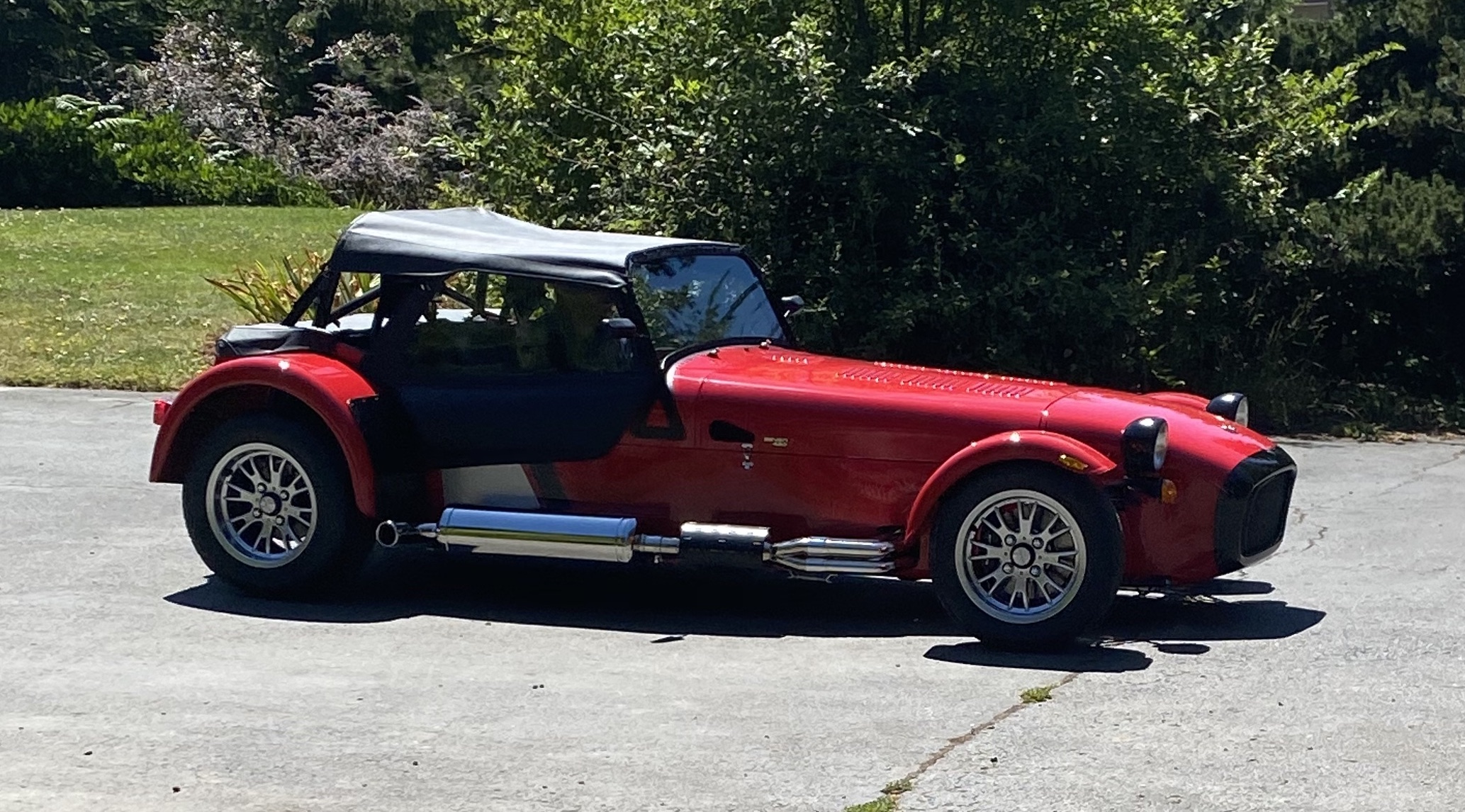
Beautiful car Bruce. That 4C is going to miss its stable mate
-
I have a 2003 Caterham with the Strattec immobilizer and would like to know how to bypass. There are four wires, so I'm guessing that two energize the loop and the other two report the resulting current. Assuming the amount of generated current generated doesn't matter, I'm thinking that I could bond the two positives together and the two negatives together to bypass. This is all guesswork on my part and access is making testing the theory problematic and I can't find any information on pinouts. Anyone have any related knowledge you can share?
-
We tested my ECU in a known good car with the same result, so the ECU has failed. I find it strange that it would fail in this way, but there you have it. At least we have a definitive root cause. @JohnCh, @sf4018 and @MV8, thank you for your help. At this point Bruce Beachman is checking to see if Caterham will warranty the part and I'll go from there. If I have to spend money then I'm probably going to spend it on the unlocked MBE for future proofing.
-
Well... maybe someone can help me interpret the results. First of all, when at the coil the logic probe shows red (12V) and flashing green (the pulse signal from the ECU). So #2 has red only, #4 (for example) has red and flashing green. This is where it gets potentially weird. With difficulty I've gotten wire to the back of the pins on the connector in the ECU on the #4 and #2 wires. At the ECU on #4 the probe shows red (expected) and solid green - rather than the faint flashing green that happens at the coil end of the wire run. I'm surmising that the solid green is actually a very fast flash that my eye can't perceive, and that wire resistance results in signal attenuation demonstrated by the faint flashing on the other end of the wire. Does that sound plausible? And... wait for it... on the #2 wire at the ECU I get red with a faint flashing green. In other words, on the #4 wire-run the probe shows what appears to be solid green at the ECU and faint flashing green at the coil, whereas on the #2 wire-run it is faint flashing green at the ECU and nothing at the coil. And for a bonus, the voltage at the ECU on #4 is 2.5V, and on #2 it is 12V. That is the weirdest bit of all of this. I've got to run but await all of your brilliant and creative ideas! At this point I'm pretty much tapped out.
-
Hold on, got one more thing I can test. @MV8's point about going through the back of the connector to test is something I might be able to do at the ECU. If so this would be the definitive test of the wire run between the ECU and coil. That run has checked out so far, not just continuity but it also has the same resistance as the other three coils, but if there is no pulse at the ECU then I'd know the wire didn't matter.
-
@JohnCh pointed out that if the issue were the ECU not receiving a trigger (i.e. the crank and/or cam sensor) to send the pulse, then the pulse would not be sent to the injector too. I just tested the injectors on #2 and #4, and both are getting the pulse. So it appears to not be sensors. For grins I tested the resistance across the coils on #2 and #4 (same) and swapped the coils and re-ran to check for pulse yet again (no difference). I'm running out of things to test and am now checking with Bruce B. to see if he has an old MBE lying around that I can plug in and crank the engine over to test. It doesn't need to start, just crank would be enough to check for the pulse at the #2 coil.


