MV8
-
Posts
2,303 -
Joined
Content Type
Profiles
Forums
Store
Articles
Gallery
Events
Library
Everything posted by MV8
-

Headlight replacement/upgrade---IE: Holley Retrobright
MV8 replied to mrmustang's topic in General Sevens Discussion
A nut plate would be less likely to spin in the thin sheetmetal of the bucket: https://www.mcmaster.com/products/nuts/rivet-mount-nuts~/ -
The horn opening should point down so rain or water from a pressure washer is less likely to enter and ruin it or freeze.
-
What have I done? Two N00bs Try to Resurrect a 7
MV8 replied to YourEconProf's topic in Build Threads
Looks ok to me. Could stand to have the brake fluid changed and rebled. Two circuits with different piston sizes and take up clearance. -
I don't see anything wrong with the stud shown. It uses a torx socket. A regular socket will not hold. If your actual stud is not shown and rounded so a torx socket won't hold, a hardware store metric bolt or stud can replace it. Also not sure why you'd want to loosen the stud. Just turn the nut. If the stud turns with the nut, hold it with a torx socket.
-
Filings are normal and that looks minor. You'd never see them during an oil change without a magnet. Use build up versus mileage as an indicator.
-
Nice and a bargain but I don't like it, because there is nothing to fix.
-
Del.
-
The 105E was only for 1961 and had twin SU H2. Twin DCOE40 started in mid-1961-on in the Super on the 109E. Ref: Coulter's Seven "Collector's Guide".
-
Here: https://www.ebay.com/itm/387920950644?_skw=lotus+key+fob&itmmeta=01JKVCEAVN8S8QY5SYF0XCX1YM&hash=item5a51e3f574:g:-rwAAOSwNkpnqmKO&itmprp=enc%3AAQAJAAAA8HoV3kP08IDx%2BKZ9MfhVJKlIeX6rTAsea3U3GWL2S8iZ8utNK7zPgr5gwAZ%2FOuFegiCNyr4tT5Aiax6CV2x4reENVzGSrtLcP9wrCQUP9fjKxygzsQeo09PZ4SyxydHRbDzojdfkhHLWlv%2Blc9BickY5koHzmr3Xh7ix2YP4PBdMpek%2Bk2E7Kw4UccWb%2F4j1fLp1mxUt%2FXpGwaCT6Lk%2FKaigEc7I7DGxRyy0PF9IyWTtbfk6Np5gCZK6vdA6mG6k1sPCcIWseGIMOrvsM1illNTJd584OPFFl9MXXUyWcAc1mt66gg2Sr8Mam%2BCdKC0LeA%3D%3D|tkp%3ABk9SR4quueyeZQ There: https://classicleatherfobs.co.uk/product-category/caterham/
-
What have I done? Two N00bs Try to Resurrect a 7
MV8 replied to YourEconProf's topic in Build Threads
I've heard that optima quality has gone down hill in the last few years. I'd use a lead acid side post with about 450-500 cca, then make cables with copper lugs and terminals from 3/8x1/2" bolts and washers. The hydraulic switch is standard caterham. You can split the power taps between the alt stud, batt terminal, and starter stud or run a remote stud off any of these things. -
What have I done? Two N00bs Try to Resurrect a 7
MV8 replied to YourEconProf's topic in Build Threads
Right? No. Will it work in the driveway and for a few months of not too aggressive cornering? Probably as long as you keep the tank 3/4 full. Yes, the link is just for a hanger so the pump does not flop around in the tank. A tank that is tilted only affects the diy baffle arrangement. When efi pumps pickup air when the fuel sloshes away, they are damaged. A miata tank has baffles inside and is shaped to aid fuel return to the sock. A Caterham tank is like an '80s ford pickup truck tank only worse, because it is very wide where a pickup truck tank is narrow, so fuel can slosh further away. The pickup truck doesn't have issue because it has a small sump tank that feeds the external efi pump and has a low pressure lift pump inside the tank that is not damaged by picking up air on occasion. If you want two pumps with an external tank, that can be done. There are also the multi-sock arrangements that could work for you and some members have used that. The simplest arrangement is what I suggested but takes some fabrication. -
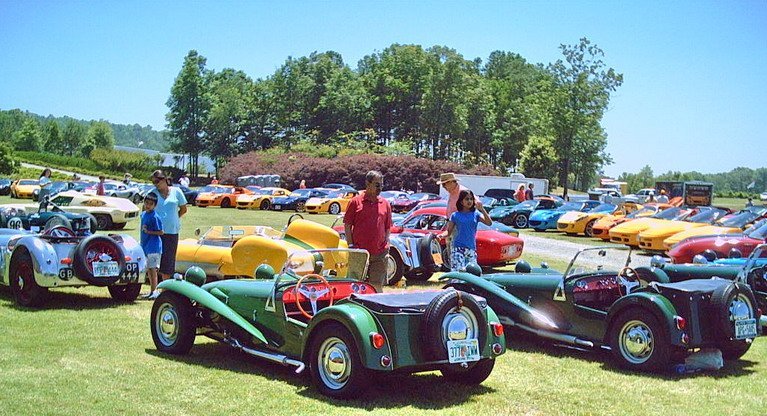
I've been to Barber a few times including a LOG event. Yes, unrelated to Skip and a lot of great examples of Lotus and unusual motorcycles...

-
https://mossmotors.com/854-720-cp-minilite-style-wheel-bolt-on-spitfire You could probably find a used set for this price. A little painting either way or repaint one of your three to be a spare.
-
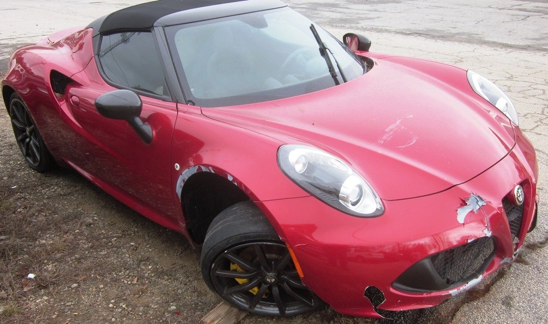
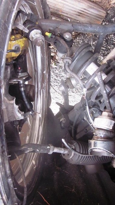
Looks like a curb strike to me too. The footwell wall inboard of the suspension was carbon fiber. No telling why it happened (maybe trying to avoid something worse than a curb) but the slick front tires don't suggest competence. Interesting to see the construction though.
-
Thanks for sharing, but a conclusion that green coolant is not compatible due to what was found in a fitting lip is weak at best. Due to residual oils and chemicals from manufacturing processes and anything that may have migrated into all the components before installation, a new build should be flushed before adding coolant. One example is the hose in your pic. It is made by wrapping uncured, reinforced silicone sheets around a mandrel that is prelubed for easier removal after heating to cure the silicone and may not be adequately flushed. Residual flux from soldering or brazing is another possibility. The label on the tank indicates the recommendation is to use their red and not to mix coolants. All green is not the same. If it were, I would not have made recommendations. The cheapest "green" is likely Supertech at Walmart and I do not recommend it. Ratios vary as well. I've found the cheaper premix to be very weak and cheap concentrate to be weaker as well for more profit, similar to the subtle shrinking of food packaging. It is on the installer to check and adjust the ratio; not to rely on the label on the bottle.
-
Saw this Alfa at my friends body shop today. Front tires were completely bald too. Also had a Graduate getting painted that was in much better shape. How do I rotate the suspension pic 180?
-
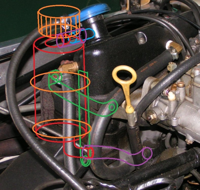
Oil filler cap: With enough bonnet clearance or shortening of the neck, a 10070 cap with vent port should fit the neck and be secure. A link to one: https://www.classicindustries.com/product/st10070.html For a cap without a port, 10098. A link to one: https://www.ebay.com/itm/276744538767?var=0&mkevt=1&mkcid=1&mkrid=711-53200-19255-0&campid=5338590836&toolid=10044&customid=e0b98187185a17df5ccae62106723d6a&gclid=e0b98187185a17df5ccae62106723d6a
-
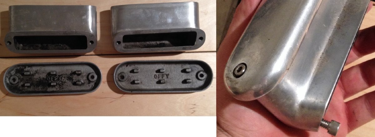
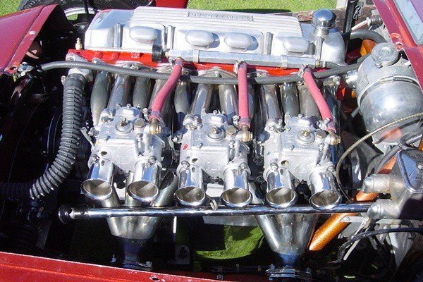
Borrowed BBall7754's pic to draw a system that adds one port to the neck of the valve cover (or no mods if using a ported filler cap), compact, self draining, with minimal oil hose.
-
https://nationalmotormuseum.org.uk/ron-hickman-caterham-seven/
-
- 2
-

-

-
I thought he pulled up to make the red lines more even/level. The upper red line is near wot and mid to hi rev but you can't see the rpms unless the cursor is place on each line from left to right. The current cursor position is 3000 and closed throttle so I guess this is not the whole curve? Notice the front bottom rows that are all closed throttle but I guess they didn't need more resolution anywhere else so why not. Tables used to be much smaller. I've not read all the posts. Totally skimmed. Rolling back into it could have been too lean before and I don't know what enrichment there is for TPS movement (separate table for accel pump emulation).
-
Don't have a pectel so I didn't look at this topic until now. The table looks to be alpha N / no MAP (load sensing). 18ms is around 100% injector duty cycle at around 6500 rpm. Left side is throttle position (butterfly angle). Column is injector on/open time in miliseconds. I would have pulled up the middle too. The block widths and lengths are adjustable but the table size is usually the limiting factor, so smaller load cells offer better resolution at low rpm and transition from closed throttle, then get wider as rpm and throttle position increase since the engine is less sensitive at higher flow. I would have the WOT/high rpm blocks about twice the size of the off idle/closed throttle blocks.
-
No pcv on this one. There are caps with spring clips that also vent but they would hit the bonnet. I've not seen that type of oil hose in many years. I expect it may crack if you bend it. Offy used to make these add on breathers. Also an example of how they fit.
-
One source: https://www.burtonpower.com/oil-filler-cap-x-flow-pinto-etc-fp630.html
-
1) Overfilling causes additional crank case pressure from the spinning crank being closer to the dynamic oil level in the pan. You can add a 1.5qt accumulator and solenoid to cope with pressure loss to the crank and top end during hard cornering, which will also lower your dynamic oil level in the pan and pre-lube the engine at cold start while adding extra capacity that only overfills during low oil pressure events, then the level comes back down as the pressure rises. Heavier weight/viscosity than necessary oil aggravates the problem. If your hot idle pressure is less than 10psi with a new filter, I would not change to the next thinner weight oil since your bearing clearances and pump wear are probably excessive. Custom oil pan improvements are another option. 2) This catch can configuration must be periodically drained as it cannot empty back to the crankcase after engine shut down. There should be a valve or plug on the bottom of the catch can. The attachment to the engine sounds good for a gravity drain, but the position and type of can is lacking. Post more pics (engine breather attachment area and an overview showing engine and firewall on the left side) if you'd like to upgrade and want a recommendation. 3) If the valve cover cap is the only other breather and is a push-on type, a full catch can could be enough restriction for the crankcase pressure from being overfilled to force the cap off but you'd also have oil all over the top of the engine. A pic of the valve cover area could help determine which cap needs to be installed.
-
Aluminum puddles at a much lower temp than steel, which is probably low carbon. Very much like what's left of a small plane after a crash.