MV8
-
Posts
2,303 -
Joined
Content Type
Profiles
Forums
Store
Articles
Gallery
Events
Library
Everything posted by MV8
-
It would be worthwhile with minimal weight increase. Borgeson double-D telescopic shafts could replace part of the column but it would rely on the driver's arms holding the steering wheel and the strength of the spokes as the column mount has minimal structure. The shafts should stay lubricated and also has a boot to keep the area clean. Oems do the same thing with an intermediate shaft. Miatas use injected plastic to hold the telescopic bits in position with no grease. A greater effort would be a large flange on the shaft forward of the column mount (blocks the shaft from pushing through the chassis mount) and a diagonal to brace the chassis attachment (less easy to break/bend back). Again, another couple pounds added.
-
I recently tested a 28 year old, econobox (2235# with me onboard) oem nylon belt (not fia or sfi) and it held adequately (car totaled, bag did not deploy). It should be noted that older oem belts with bags have a "rip stitch" folded loop to eliminate peak loads on the body at the belt, relying on the bag. Newer oem vehicles have "smart" tensioners. I expect FIA polyester to provide some give under peak forces where nylon SFI or oem may not. FIA would be a good idea for road use and more likely to be needed imho.
-
Looks like it would be easy to dent with a leg wrench. I'll look for something similar but you may need to change them all if there is no identical match available. Need the wheel bore size. EDIT: May fit but plastic snap-in with a 2.5" hole in the rim: https://www.demon-tweeks.com/us/caterham-wheel-centre-cap-cat77295/ https://www.demon-tweeks.com/us/caterham-alloy-wheel-centre-cap-badge-cat77295badge/
-
Vin, are you looking for the center cap that attaches to the wheel or the cosmetic disc that attaches to the center cap? KN made a number of wheel models that may share center caps but you should measure the size of the hole in the wheel or the cap you have. Monitor caps are available but these are Jupiter wheels.
-
Post a pic of the bezel you have.
-
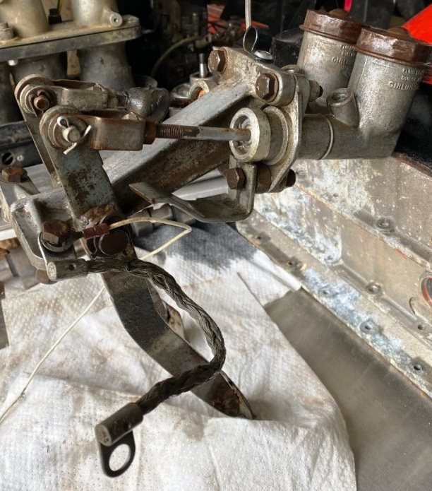
It looks more like a motor mount with a flange. I posted a pic here:
-
A kit like this would be fine for just about anything. Enough fluid is added to the jar to cover the end of the hose inside and the lid is kept tight so the vacuum level is maintained. Again, don't bleed a clutch the way you bleed brakes. https://www.ebay.com/itm/176413002663?itmmeta=01HZS2DQ5KE4250HFW4ZWYT3KV&hash=item291308cba7:g:k3QAAOSwZfFmYqDS&itmprp=enc%3AAQAJAAAA4DblZ6GIUIg8erC3knJnm%2BVQz%2BvA%2FtxwT414IR%2F0aaxokuv7LUC8qgeDpt0l90uP9%2FxTdSTj1zhwbfCjQYe6sclkyEd7IpQJvL4OLKZpR4GZ4TCySFrcR6Po7etfpr%2Bh%2B0U35LRY%2BGxhkRF4hu0sCw3qnygnGEWZZiA8N%2B9me%2FE4Tgzofpmtyfo%2Ffxy3jzvwWJEgudVkFX3iebv2ECAJJcF%2BY5P9invnMLGe0Hb2%2FqnMkvG4f6SDkCV6fou0iRoysysK4gT2KXYHTv8deVeqxuE3Ihp5auUhXVq6QR57gQh8|tkp%3ABk9SR_7ytqL-Yw
-
I've found multiple methods are sometimes needed to fully bleed a system and can easily account for your issues. I typically use the tools in this video but on the bleed screw and usually bleed a clutch the opposite of brakes as they do in this video.
-
Unless the pedal does not travel as far when bled, you are getting full stroke out of the MC but I don't understand how you determined what stroke you should be getting at the slave. Piston travel is inversely proportional to the diameters squared. If you go ahead and drop out using PI, slave stroke is equal to the MC stroke X master bore squared over slave bore squared. 0.390625/0.5625 = 0.694 x 1.375" MC full stroke = 0.954" of slave stroke. What method are you using to bleed the system? How did you ensure there is no air pocket in the slave?
-

2004 WCM Lotus 7 for sale---Car has been Sold 6-21-2024
MV8 replied to mel kuipers's topic in Cars For Sale
Fully dressed/equipped is supposed to be about 1240 lbs. Fiero/chevette spindles (a great choice), aftermarket/racing brakes, and subaru irs components. No "bad" parts imho. -
I will state the obvious if it isn't clear to all. The slave stroke is limited to the MC stroke. These are normally 1:1 (3/4 bore slave, 3/4 bore MC). You are trading a longer stroke for lower pedal effort with a 0.750 bore slave and a 0.625 bore MC. A little more effort with a 0.700 bore MC is probably your best compromise, but let's see if you are getting everything you can from the linkage. On the car, with the red line disconnected at the MC or fluid mostly drained, what is the total MC push rod travel, measured at the entry to the MC body, from released (pedal up) to the firewall? What stops the pedal travel/MC stroke with no fluid? You can place masking tape around the shaft and mark with a pen and straight edge, then measure the distance between marks.
-
Yes, but there seem to be many good choices. See my March 16th post here for details on the applications:
-
I am confused. Is the following not accurate? Post #8: "After careful measurements, I show the following: Master cylinder rod travel = 1.04"" Post #15: "With the current pedal setup, I have no problem pushing the pedal all the way in. It does not hit the fire wall, but it does bottom out the MC." The clutch would not bottom out. Your pedal adjustment should look very close to this photo of a '61.

-
In general, an installation should have a safety margin to prevent total hydraulic failure due to stacking tolerances. My understanding is: 1) you carefully measured the MC stroke to be 1.04", 2) you are bottoming the MC, and 3) the design stroke of the MC is 1.375". This tells me that the pedal linkage is preloading the MC piston by approx 3/8". It also won't self-bleed if the compensation port is always covered by the piston. Linkage wear and less-than-ideal operating angles contribute to a loss of MC pushrod travel. Also, I don't know if the release bearing is the type that is designed to turn with the pressure plate all the time or just when shifting, which requires clearance to the pressure plate. A return spring on the fork suggests the latter. I've not read the mechanical adjustment procedure. Pictures from the side of the top of the clutch pedal area (to include the MC mount) with the pedal released and fully pressed might help us to see the issue. Feedback from a second set of eyes is usually a good thing.
-
I would not assume the installed travel is as much as the max design travel of the MC. You'd need to raise the pedal attachment point (slightly higher effort/reduced pedal ratio) and fit an offset pedal fork (to eliminate the need to raise the MC to match). Doesn't need to be as rigid as the brake fork since the pressure is just enough to move the pressure plate fingers.
-
You could have a pedal made to fit you where the master end is a half inch further away from the pedal pivot and offset to make the most of the ratio, as well as longer on the lower end to accomodate a shorter length foot (ball of foot closer to the floor) for more leverage to make a larger bore master acceptable. Could also just fit a 0.700" bore master.
-
The pedal has a ratio that rises and falls. It is not fixed throughout the pedal travel. I thought the issue was effort, not stroke.
-
109E Cosworth static timing is 4btdc. I thought you had the 105E which is 10btdc. Lucas gap .014-.016".
-
The pedal pushrod should be adjusted to where the upper pedal arm is about 35 degrees clockwise from vertical, to help ensure the net pedal leverage ratio is maximized (mid-pedal travel is 90 degrees/arm vertical). An AN3 or 4 line should reduce the pressure loss though the pressure is just a fraction of what brake pressures are. I don't know if there is a ball stud length adjustment to make the most of the forks range of motion. Do you have a three finger or diaphragm pressure plate?
-
Yes, as a more reliable indicator of tdc than an existing mark on a pulley. The purpose is to get you in the ball park for cranking, then set the timing with a dial back timing light or use the methods I described. It sounds like you are trying to do everything at the same time, cooling, clutch, timing, carbs. Do you know if you have the 4.56 or 4.11 final gearing? This engine should have had SUs or a single dcoe. Probably should inventory the carb assemblies.
-
I expect the twin cam head would clear an S2. The pinto, lima, and cvh are similar in height to the xflow. Zetec and duratec are very close to each other in height. Toyota 4age, 22r, and Dodge slant six (too long) are in between the two ford groups.
-
What are you saying? You lost me.
-
I suggest rotating the crank key slot to the top center (0 degrees/tdc for #1), place a small piece of tan, masking tape over the pulley face adjacent to the timing tab, then using a sharpie or ballpoint, mark the pulley where tdc is indicated by the tab. Align #1 cap post to the rotor. Starting should be easier. Sort out any idle speed problems, then adjust the timing based on the pulley to 10btdc and appropriate idle speed. It looks like you have room to run an 8-10 inch electric fan behind the radiator with the nylon rod mounts through the core. They have foam pads so the core is not rubbed by the nylon and are easy to remove but one-time use. Use a relay with power from the alternator and controlled by the existing fan circuit and/or a toggle. I'd also remove the oil cooler to eliminate the oil pressure drop, cooling when you want to heat the oil quickly to running temp (engine wear), and the short life of most rubber hoses with hot oil. In general if the engine while cranking doesn't rotate smoothly/near constant rpm with the starter, the timing is probably way off. Imho, while not ideal, I don't see a significant issue with the custom filler tank.
-
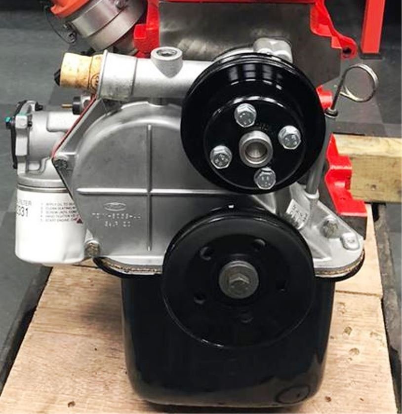
I still think you have abnormal restriction through the head gasket. Also, the crank pulley should be bigger than the water pump pulley which is most critical for lower rpm. Here is a pic I found (happens to be a xflow). Note the crank pulley is bigger. Looks like it should be 4.75-5 inch od if the water pump is 4.25. Senc may have an aftermarket smaller crank pulley too. It sounds like the crank pulley is undersized, slowing the water pump: https://www.burtonpower.com/v-pulley-crankshaft-4-steel-fp224.html "Pulley is also smaller, reducing speed of water pump..." This place offers many pulley options. May want to ask how big the standard pulley they offer is: https://anemboengineering.co.uk/x-flow/
-
What are the diameters of the crank and water pump pulleys? I've seen bits of rubber clog the small holes around a single cylinder that caused an overheat, but that was a totally different engine (455cid Olds).