MV8
-
Posts
2,303 -
Joined
Content Type
Profiles
Forums
Store
Articles
Gallery
Events
Library
Everything posted by MV8
-
Take the bolt to Home Depot and match up a nut out of the bins that will screw on by hand, note the thread size, but buy the nyloc version in the hanging bags. If you cannot find that, find a bin bolt the same thickness and length along with a nyloc nut.
-
Electronic/breakerless trigger ignition does not require a timing change, but breakerless isolates the ignition coil circuit (coil primary amps don't run through the points) so the coil can be much higher output for a wider plug gap, with little effect on the ideal advance rate but the total advance needed may be less. Most engine improvements reduce the total I think you are referring to Tony Weale's book reference, which is for engines with a specific "UL" specification (UL=UnLeaded?). 95 octane is shown as 95 in the UK (RON measurement), 92 here (AKI measurement or RON + MON/2) for the same octane fuel. Ethanol also has the effect of increasing octane and is factored in at the pump (though the percentage varies with the season despite the pump label due to ), but it can fall out of suspension (leaving low octane fuel), attack all rubber in the system, and absorb water to corrode everything internally (ethanol is hydroscopic like brake fluid, but not as corrosive to older fuel systems as alcohol or methanol). An engine (EFI or carbs) designed to run on gasoline will run leaner on common 10% ethanol fuel with reduced range due to the lower btu content and greater burn rate if the mixture is adjusted. Ideal advance is not directly proportional to rpm. Mechanical and traditional vac advance are very limited and mechanical all in by 3k is a good compromise. With modern tools, timing can advance to peak around 3k then slowly retard due to the improved burn rate from the turbulence at higher flow rates (like aero drag on a car moving faster). Most efficiency improvement result in less total timing. Cam overlap is similar to egr mixture dilution and requires a higher advance rate and total since it is not an efficiency improvement. How deep do you want to go?
-
It looks to me like the brkts bolt together first with a captive nut on the riveted plate, then the tank is added last.
-
I don't have one of these but read the documentation to see. The green led is for static timing to TDC, with no static advance. The "centrifugal" curve in the program duplicates an actual fly weight distributor curve. If your rotor can turn 25 or so degrees without the crank rotating, you have a real flyweight distributor and the program curve should not add any advance beyond the initial 10 deg btdc that is needed because you lined up the green led and locked it down. The "vacuum advance" curve duplicates an actual vacuum advance using a MAP sensor. Technically, all modern cars have a (more reliable) form of vacuum advance. Lots of options. Cool product.
-

2016 Caterham - Sigma Engine - How do I adjust throttle position?
MV8 replied to Tyler's topic in General Tech
If there is clearance between the pedal and firewall at WOT, it could be shimmed at the top but all the hardware should be longer and use nylocs or double nut to allow a lower torque spec without vibrating loose. You may not be comfortable performing arts and crafts on a throttle pedal servo, making it a non-standard part that will wear and eventually need to be replaced. Better to bring it back to where it should be in relation to the throttle and replace or mod the seat to move you away from the pedals. Sit in the car without the seat and just a thin mat to get an idea of how much room there can be. -
1998 Caterham Seven VX, Vauxhall 1600 8V - SOLD!
MV8 replied to peregrinemotors's topic in Cars For Sale
Interesting. While this engine family is a rare sight in a Caterham here in the States, it should be largely interchangeable/upgradeable with the 80-90s GM (cavalier, sunbird, grandam, and fwd T-type) SD MPFI 2.0L base engine (still square; bore and stroke increased with a 6400 rpm redline), which was also offered turbocharged in GT models (LT3, 9psi, 165hp/174ftlbs. Being built in Holden, I expect the engine was made there as well, making it an Opel "Family II" which is the larger block family with a minimum displacement offering of 1.6L. The bell housing is not the same as the v6-60 or Quad-4 due in part to the high starter location on the intake side. https://en.wikipedia.org/wiki/GM_Family_II_engine -
Need a little help please. (Measurement)
MV8 replied to windsurfer's topic in General Sevens Discussion
You're right. I didn't realize they moved the lights forward on the newer cars. -
Need a little help please. (Measurement)
MV8 replied to windsurfer's topic in General Sevens Discussion
Windsurfer, the bracket in the picture you posted looks to be mounted in the wrong location (too far forward). -
Both are fine but retap is not necessary with the right fitting, which may be included. The threads of the sender or mechanical gauge fitting should be the same as the port in the bolt-on filter manifold. Your manifold may be 1/8 bspt, 1/8 npt, or M12. The picture above shows a compression fitting screwed into the M10 fitting and clamping the tube. The male threads of the compression fitting maybe 1/8 bspt or npt where it goes into the female end of the M10 fitting. I expect this to fit the filter manifold directly without tapping but I don't know for sure. Another option is if you want M10 and the manifold surface is flat enough to seal against with the washer, the manifold can be removed and tapped for M10 (or m12 if you want to use that size), cleaned of shavings, and reinstalled. The m10 and m12 do not seal at the threads. They both rely on the washer to seal.
-
I suggest never trying to remove it (fittings don't make good taps and the filter is usually before the fitting port so the shavings would not be caught by the filter). The rover oil filter brackets are available new just in case or it can be machined.
-
I don't remember when they stopped installing the rear mounts, but I expect a '64 to have front and rear mounts, with the fronts being bent square tube welded to the headlamp bar and the rear as bent square tube. Would pictures of the supports be helpful?
-
Since you intend to modify, you could use the engine and chassis as the jig, with the chassis and engine supported with wood or stands (lifting the engine relative to the chassis slightly to where the bracket will sit in place without squeezing/preloading the mount). Make the ends of the bracket, bolt those on, then fab the middle as you need it to be for position and belt alignment. Card board is very useful for making perfect templates to use as patterns for the steel. Tack it all together, remove, weld, recheck fit, then paint.
-
Looks to be a complete spitfire frame and suspension with a bolt-on body. Spitfire fuel tank and filler also.
-
Nothing against Budlite's mod. Many ways to do anything well.
-
That is adorable. No idea on the kit mfg. Any pics of the rear axle/suspension/boot well?
-
No, loop over to reach the valve, not under.
-
The heater cable is the minimum acceptable length for this arrangement. The valve end should be above the control end to minimize the bends/friction.
-
Online stores can be wrong too. The only practical way to know if it is bspt or npt is to use an sae thread pitch gauge on the old sender. Thread pitch gauges are included with tap and die sets. Sae gauge is used to show threads per inch even though bspt is not sae. There is usually a one thread per inch difference so npt and bspt don't actually mesh evenly. Metric and bspt "go together like peas and carrots", so I expect it will fit.
-
Fwiw, I think you nailed it down to the anglia part. I'd probably go back to standard.
-
The K series is likely bspt, not npt. Should be m10x1.0 for the new gauge but it looks like it may be 1/8 bspt above the m10 fitting. You could remove the m10 fitting from the end to check. If it is 1/4 bspt instead of 1/8 bspt, there are adapters or a 1/8 bspt compression fitting could be used if sized to match what is probably a metric sized capillary tube. (FWIW, bspt and npt are not interchangeable (slightly different thread count). They will seem to fit each other but will leak a little even if using sealing tape.) The bspt top thread damage should not be a problem.
-
If the clutch cable is in good shape and lubricated, consider it may have an "upgraded" heavy spring installed in the pressure plate. If it takes full pedal travel to shift normally, then going hydraulic may not help.
-
1962 Lotus Super Seven Clutch Master Cylinder
MV8 replied to TEM's topic in General Sevens Discussion
Clutch hydraulics are usually 1:1. Reducing the brake from 3/4 to 5/8 reduces the pedal effort for the same stopping power but the pedal travel needed will increase. I think I'd replace the clutch with 5/8" and swap the masters. -
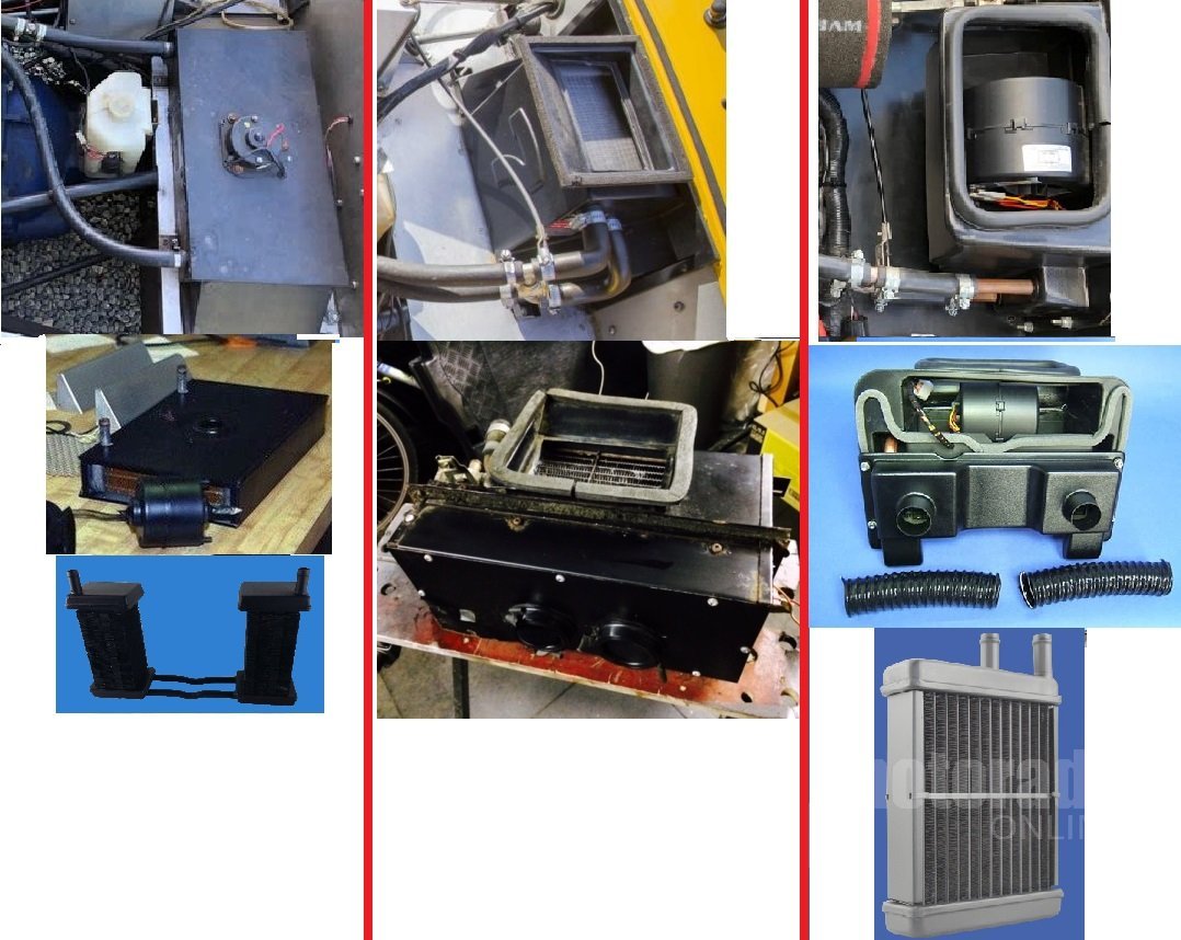
Lotus S4 7 heater assembly needed/ wanted to buy or information.
MV8 replied to mr.vman's topic in Parts For Sale / Wanted
Left column. Yes, spitfire tubes would need to be cut down.
-
From least to most restrictive filter (and least affected by a dirty filter): 1) foam sausage, 2) two individual mesh covered foams, 3) tall pleated cotton gauze, 4) short pleated cotton gauze, 5) pleated paper, 6) screened throats.
-
FWIW, a traditional tps should last 100k miles. An inductive tps like this with no wiper to wear out and a rare earth magnet should outlast the car. Otherwise, it looks like an older honda tps but with an integral cable. Traditional and inductive serve the same function.