MV8
-
Posts
2,303 -
Joined
Content Type
Profiles
Forums
Store
Articles
Gallery
Events
Library
Everything posted by MV8
-
It depends on the lines. Generally not a problem to assemble your own with reusable fittings. For oil where pressure drop is important, "full flow" elbows should be used. Routing, support, clearance, and stress relief (no lines installed without slack) are all important. AC43.13, chap 8 is a good place to start: https://www.faa.gov/documentLibrary/media/Advisory_Circular/AC_43.13-1B_w-chg1.pdf The variety of fittings is huge. You must be more specific. If the hose is the right size for the fitting and the pressure appropriate, it doesn't matter if the fittings on each end are different.
-
C152 is the evap control solenoid. Nothing but the evap cannister and the intake manifold source should be connected to that. There should not be a tee. Pictures at a distance of two feet would help me to understand. Plugging vacuum leaks is helpful if it doesn't cause other problems. A small bolt can plug a vacuum hose to act as a cap.
-
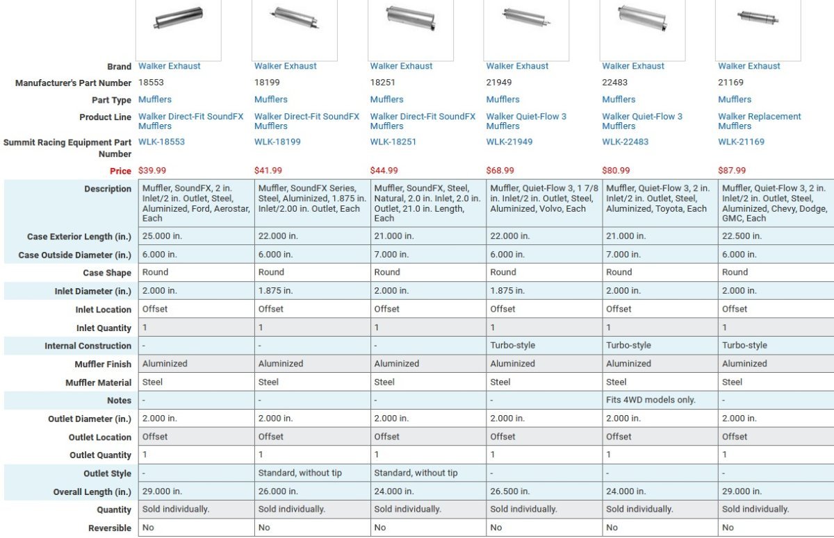
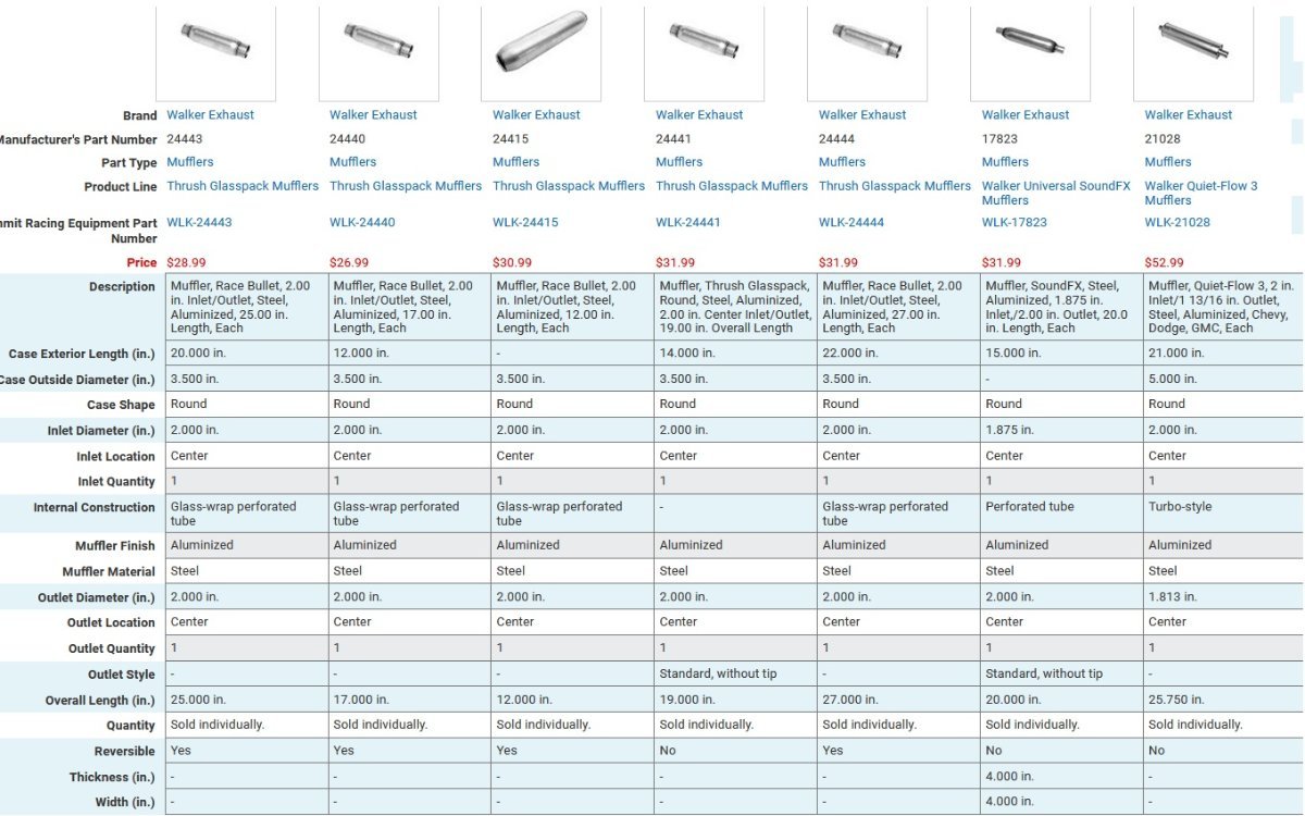
These may give you some idea but not for 1-3/4 pipe. Echoing Scott, what is the pipe od? What is the length from the end of the pipe to the fender? How many inches from the pipe to the side of the car? Can you weld or will this just be slipping together and clamping? A picture might help too, including the unsuitable muffler you have now.

-
No experience with these engines or ecus, but what makes you think this is a wideband and not just a four wire hego? I suggest fitting a replacement o2 sensor for this ecu. lambda and wideband are not compatible/interchangeable for wiring or sensor output without software calibration. I don't know why a fuel pressure relay would have a vacuum port but the evap cannister purge does. I don't see electronic egr vacuum control function on this ecu diagram. This is very confusing. I would expect to see a vacuum hose from the intake manifold to a fuel pressure regulator to reduce pressure (and richness) at idle and part throttle, and generally a fuel pressure of around 40 psi at idle.
-
I don't know where you can find shared chassis repair data. The rear suspension Z-link upper arms are bent by design at the front for axle tube bump clearance. The rest of the upper link, the lower link, and the A-frame tubes are essentially straight. I suspect that in the side-view, the straight section of the rear links are parallel to the front links at loaded ride height (rear link chassis eye higher than the axle eye) for some anti-squat at the expense of pinion angle in bump and tighten on roll (oversteer). I doubt the unique, large compliant mounts on the chassis are available. You may need to make bolt-on spherical mounts to replace them (such as a 1/8 flange, a 1/8 wall tube boss, and a press-in 1/2 inch id spherical insert). Other bushes are likely y9 and 636. The rack should be from an escort mk2 (short pinion). I don't expect the wiring is much different from an s3. I've not seen an s4 specific schematic.
-
News to me. Maybe also a variant in the same wide body but standard width seats to fit a larger tunnel, for a larger bell housing and clutch, for a straight six?
-

Help Troubleshooting What I Assume is a Grounding Issue
MV8 replied to Stang70Fastback's topic in General Tech
Generally, a short ground strap across the left rubber engine mount and a strap from the battery negative to the bell housing provides the complete circuit. Without the chassis ground strap, then engine would still ground poorly through the throttle cable, clutch cable if not hydraulic, and the ujoint needle bearings to the axle through the parking brake cable. The starter grounds through the mounting bolts. -
Very interesting story. I guess each seat is four inches wider with the body and chassis eight inches wider than a traditional S4. What S4 specific parts do you need? More photos please.
-
Help Troubleshooting What I Assume is a Grounding Issue
MV8 replied to Stang70Fastback's topic in General Tech
Yes, that's it. There is room for improvement for a more reliable ground point. Paint is an insulator and this relies on the bolt shank contact with the drilled hole. For comparison, most oems use many small grounds with sheet metal type threads to provide the path to ground through the threads and a grease or sealer to prevent corrosion. I'd remove the bolt, sand, scrape or razor the paint off the bottom of the panel around the hole, add a finger wipe of grease to the surface, then fit a serrated washer under the head. Home improvement stores should have serrated washers that will fit well. Easiest to just take the bolt to the store to match it up with a washer size. I'm guessing 5/16-3/8" washer. A normal washer will work ok if the paint is fully removed where it contacts the panel. -
Help Troubleshooting What I Assume is a Grounding Issue
MV8 replied to Stang70Fastback's topic in General Tech
The instrument ground loom grounds at the wiper motor bolt so you might try removing, wire brush, reinstall. The cooling fan has a separate circuit from the heater blower/instruments/fuel pump circuit. May want to verify by pulling the fuses to see what works and what doesn't for each fuse. If it isn't easily corrected/determined, you might use the existing fan power to control an add-on relay to be located next to the fan and fed by the alt batt stud with 12-14 ga wire and an inline fuse holder. Then the amps through the green wire will drop from ten or so to less than one amp. The voltage at the fan will be higher as well so it will be more effective. -
Jag XKE mounts from what I've seen.
-
Just trying to prevent valve bounce and float at high rpm. Looking for adequate pressure for the cam recommendation for rpm range and no more. Anything more than what is necessary just increases wear on the cam and valve train and makes zinc additive more important. Factory roller cams typically have very low spring pressures and don't need as much zinc (if memory serves, the early roller 5.0l mustang had 65 lbs closed). In my experience, lower than recommended pressure springs can be used without issue but I don't tend to rev near the limits. Tapered or "bee hive" springs are better in part because they allow more compression before spring bind, allow a lighter, smaller od valve keeper, and weigh less because less wire is needed to make one. Smaller valve stem seals may be required to clear the smaller id coils. There is a drill bit/cutter for machining the guide. It pilots off the guide bore.
-
New engine mounts should reduce the total engine movement.
-
Based on what I've seen, Cat doesn't add a heat shield. Some alternators come with them and some aftermarket suppliers offer them separately depending on the model of alternator.
-
Pricey for a standard alternator with a pulley swap, a connector, and an adjuster. https://view.publitas.com/burtonpower/2024-catalogue-pages/page/99 Typically 35a rated where your original is 60a but 35 may be adequate: https://www.ebay.com/itm/163156618086?itmmeta=01HWWWNN928T6DGMBYTXR7N3ZZ&hash=item25fce46b66%3Ag%3Ai4oAAOSwYkRcj1AL&itmprp=enc%3AAQAJAAAA4PdYzTUYeg7GAKjq7PVjTYcQ%2Bga8M%2F1l%2BerU%2BfRASStEpwhqA8AFBwBI64X1cDKXjWyZO13EPM6vBh7Fdyy0OIq8kLOYMuFjBquK1P9yfjaaR6v5SzEk2O5O77Iprze4L8nP2xYdUEwS1bkUE7razDKIaXVWY6th%2BTg4N9OK4XmFeKzcje4M17hzoMzFTvw%2F3psQbmxTnhaq5jfljjmTk4yZAEDzcw2FLVg506FLy8Xh6Ja%2BcdxJ%2FW%2FngUq%2F8jWn2BFPB4mqikMDgoLoXkx7mb%2F5FB6aKgVOtaaiMYLD0e8c|tkp%3ABk9SR-DU1pznYw&LH_ItemCondition=1000 plug: https://www.ebay.com/itm/302280093149?itmmeta=01HWWX6PC6NQA3470VA8PS9KXZ&hash=item46614c2ddd%3Ag%3AKEIAAOSwpkFY7OPu&itmprp=enc%3AAQAJAAAA0KSnVobYwKsBTD7ljSAmIxxBY4qqHFeS8OMk6lAyHXbgm6ZTQQxeTGfdtA2Dw4LVdKRC5gpcij0NbXQlALIE0JfAf1QEWa7z2j7CPl%2BV%2FdWxTRhChKUjaNCCa%2B68LWAKHflEuOiY3Z%2FjTYxbiZxhd3d%2BNmftdKEiVl6EFlSVaUETZJRc9Ap%2BD6s7DGAw%2Bw%2BqlvqgvAeyuH86FxNU6kill%2FwrP8zdflf9cdXUcihzlq0I7KGGiiicR7bZcW%2FxDmP1RvdpmguBcgBV1%2F56Mdncvm0%3D|tkp%3ABk9SR7rmmp3nYw&LH_ItemCondition=1000
-
I'll assume you want to stay with the original alternator/ no adapting. This regulator has many agricultural applications. https://www.ebay.com/itm/115436090730 I noticed the header proximity. A little header wrap on #1 or the back of the regulator should extend the life.
-
Should work fine. Not much to go wrong. A short cylinder and a pressure gauge.
-
Sounds like the regulator. https://iat-usa.com/product/09620-magneton-alternator-voltage-regulator/
-
Zetec and Caterham 6-speed hydraulic release bearing (slave cylinder)
MV8 replied to Pokey's topic in General Tech
Sorry I missed your post. I agree that the stroke increase probably contributed. Sounds like you sorted it out. Interesting to hear about the two lengths though. -
I guess it is the 2016 and newer six speed that is too big? It looks bigger than the older six speed.
-
I would consider swapping to the miata six speed, change the final drive ratio to 4.30, with a tighter spread 2nd through 6th than the cat six speed 1st through 5th but the same top end. Food for thought .
-
The wc in the link is listed as having a 0.875" bore, not 0.750".
-
The ebay listing won't interchange with the pistons shown. The bore is unknown so interchange with your forked pistons is unknown. Dual forked pistons, right body shape, right bore: https://www.burtonpower.com/rear-wheel-cylinde-wc1693be.html Apparently the 9 inch drum did not come with the larger, 3/4 bore WC in a Ford application. I didn't try Moss.
-
There have been different axles installed over the years. Pics of the drum and parts would help.
-
Zetec and Caterham 6-speed hydraulic release bearing (slave cylinder)
MV8 replied to Pokey's topic in General Tech
There are several ways for this to have failed. I suggest correcting the pedal travel with a pedal travel stop, buy another HRB, and carefully follow maintenance practices. The hydraulic release bearing assy (HRB) has a maximum travel stop. There is a coil spring inside the green boot/gaiter that keeps the assy fully extended until installed which compresses the assy. The installed length of the HRB must be short enough that one full stroke of the pedal will not extend the HRB beyond the fully extended length. Some things that will cause the HRB to extend further than normal include turning the flywheel for a new wear face, extra pedal travel(master stroke), a larger bore master, or engine thrust bearing wear. The HRB should be bled while still accessible. DO NOT use the clutch pedal to bleed the system when the trans and engine are not fully bolted together. Use the HRB as the pump by squeezing it to remove the air. If you use the pedal/master and the HRB is extended, it will likely fail immediately or at least leak. There are other ways to do it but this is safer.