MV8
-
Posts
2,303 -
Joined
Content Type
Profiles
Forums
Store
Articles
Gallery
Events
Library
Everything posted by MV8
-
55 amps is marginal. The rating of alternators is normally the maximum output that can be provided intermittently and at much higher rpm than off idle. I'm sure the oem ford alt has more output off idle. I don't know anything about your accessory drive, but "racing" types typically have smaller than oem crank pulleys that slow the water pump and alternator for less parasitic loss and reduced cooling and charging efficiency. Also, a geo metro cooling fan should be a much lower electrical load than a good high output fan suitable for this car. As long as the light is just a brief flicker, it will probably be ok but don't expect the alt to charge the battery very well/quickly if jumped off. If you upgrade lighting or the cooling fan, consider an upgrade to the alt or pulley ratio if less than oem.
-

Jake LaMont's How to Build A Competitive (and legal) FF 1600 Engine
MV8 replied to Wayne Stambaugh's topic in General Tech
https://books4cars.com/bookLandingPages/70_FF_Eng_Prep.php -
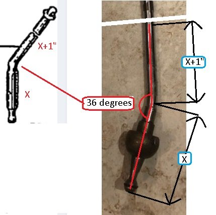
Based on the drawings, it looks like a 36 degree bend with the upper end an inch longer than the lower. A lug bolt hole in an old steel wheel would be useful to hold the lower for bending with a torch and would shield the lower as well as support the shaft better than a vice to prevent gouging the shaft. Wet rag around the lower also helps. Only heat the one inch of bend area (to keep the bend tight versus an arc) to near cherry with a 3/8 gas pipe over the upper for a little more leverage. I doubt a hand bottle/map torch will get hot enough but worth a try. A threaded rod coupler can be epoxied into a cue ball for a nice shift knob if you have large hands. Drill the ball to the diameter of the coupler flats, epoxy coat the hole, fully thread a bolt into the coupler so the threads stay clear of epoxy, then tap the bolt to insert the coupler. Add a jamb nut. If you have trouble cutting threads into the shaft, a bolt with the desired threads can be butt welded to the end of the shaft and ground to level with the shaft if the butts are vee'd or a gap created to be filled by welding.

-
That looks like the "Sigma and Duratec" listing for $408 inc. vat. The "Rover K" and "crossflow" versions should be interchangeable on the same mounts but have sensor ports and fan brackets.
-
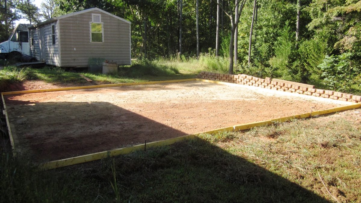
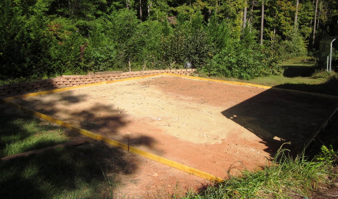
Scheduled ready mix delivery. Will also get a layer of plastic/vapor barrier. 25x26x3.5 for 7 cuyds. Had extra retaining wall block so I just kept stacking until I find another use for the excess. Added a hanger strap to mount directly to the cement trucks chute and made a darby from more repurposed scrap 2x4 and deck board.
-
In general, besides checking your email accounts spam file, forwarding settings (i.e., not logging in directly to the email account) can block some traffic. I don't do notifications and just check back from time to time.
-
Any casting numbers on the hub adapter?
-
That makes sense. Yes, the escort rotors are different.
-
I agree, though I'm not sure AWOL is the best word. "Joe plumber, you are essential/excepted. We have some clogs in the system we want you to observe, but not actually clear at this time, because we "never let a good crisis go to waste". You are not eligible for furlough. You must expend your remaining time and financial resources to continue working indefinitely without pay. Your accrued benefit of annual and sick leave is cancelled. Back pay is not scheduled, much less assured. Even if furloughed, you are not eligible for unemployment benefits and cannot return to the plumbing industry briefly as that could be a conflict of interest. Have a nice day". Some of this changed with PL116-1.
-
Pics of Wdb's shifter and trans found here: Ditto on it being the first diagram I posted but I expect it should be a flat sided ball tip like this remote setup has on the forward end. Maybe Wdb's is using v6 application Type 5 (would have 3.16:1 first gear versus 3.65:1). https://www.ebay.com/itm/155713860927
-
The reasons for or against a CR notwithstanding, it's good for employees to be paid if they have to work anyway. Last time it was 35 days.
-
Many different options for full sets on ebay as well for $150 or less. I would not hesitate to use a capillary OP if the capillary is standard kit and separate (so a capillary issue does not mean tossing the gauge for new). I see India selling knock-off Massey Ferguson and Smiths full gauge sets for $45 while the triple gauge, under dash sets that have been around since the '70s are now $100 or more. For appearance and protection, the white nylon capillary tube can be run in split loom or aluminum versa tube.
-
The bearings and races should be marked/etched with part numbers that can be cross-referenced. Sounds like you are using '90 HF front rotors on the Birkin rear hubs (appears the '90 CRX had only one rotor for the rear for all sub-models). Use a lathe to open up the rotor pilot to fit so it will stay centered and not wobble.
-
Maybe this will help.
-
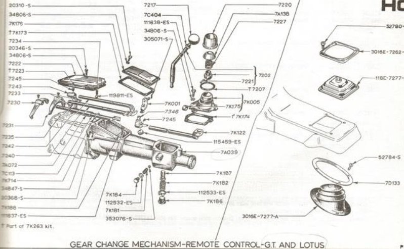
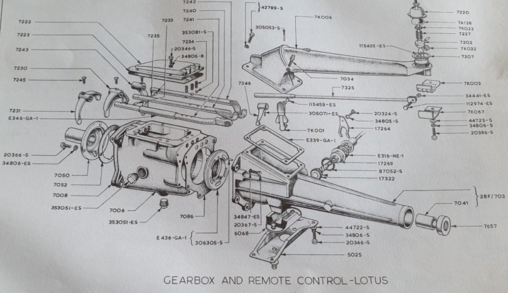
Also, there was an exposed remote linkage above the tunnel on the earliest models, then an adapter for ford transmissions where the shifter opening was not located close to the rear of the transmission. These have a sloping cover on the tail housing behind the main case cover and used a triumph remote shifter turret assembly. This trans was the basis for the later 2000E/Bullet, still with a remote linkage option. 100, 105, 109, and 116E were used on the ford powered S2. It looks like you have the 116E to me also. I can post a pic of the ford engine and trans with the adapter if anyone is interested.
-
FWIW, an under-bonnet pleated cotton sandwich cone would be much less restrictive. The design above blocks off most of the sausage filter.
-
I found five Rotus cars online and compared dashboards. Each was unique for panel layout and switch gear.
-
I suggest taking a new photo with a light on the transmission and from a lower angle and closer to see the back of the switches below the gauges. The switch comes out from the side of the instrument panel displayed to the occupants. There should be four (usually plastic) tabs that secure each switch to the panel; two on each short side of the switch body (top and bottom). These must be squeezed against the switch body while lightly pushing the switch from the front. A very small flat screwdriver works well to squeeze one tab at a time while trying to walk/wiggle the switch out of the panel. A narrow blade pocket knife can also work well. Once you have released and pulled the switches out from the display side, take photos. If you find the switches have individual wire connectors, do not unplug any before taking a picture. Make a drawing of the connector side of each switch, numbering the connections/positions then make a list of each connection by color, number of wires in that one connection. If there are identical connections, use masking tape and a pen to differentiate. Once labeled, remove the switch, accurately measure the opening in the dash panel and use a light to take photos without shadows. A magnifying glass can be used or good quality setting photos that allow magnification without a glass. Good digital cameras will sharpen a photo about to be taken when the "shutter" button is lightly pressed and the photographer pauses before fully pressing the button. It is unlikely the wiring is integral to the switches.
-
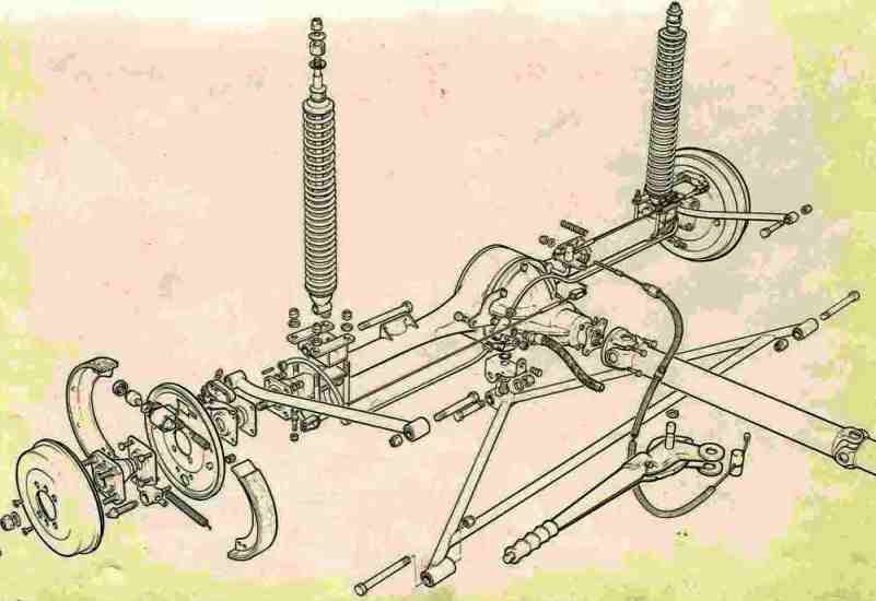
Yes it is but it is just a photo I found. I don't own a Seven. The bend maximizes clearance to the U bolts that changes in cornering roll. I don't know what the operating angle is but I would expect it is probably supposed to be parallel to the transmission output shaft. Ideally it should be less than 1.5 degrees and the same at both ends of the driveshaft to prevent velocity changes with each rotation. A digital, magnetic base angle finder is about $13 on ebay. Since the axle perches are fixed/welded to the axle tube, the only way to adjust the pinion angle (directly versus trans mount shimming) is with arm length. I don't know that anybody bothers to check or adjust. May be fine with good arms.
-
Should be some information molded/etched into the switches that could narrow it down. Look like mgb parts except for the stencils.
-
On-track incident - Help with damage assessment
MV8 replied to KnifeySpoony's topic in General Sevens Discussion
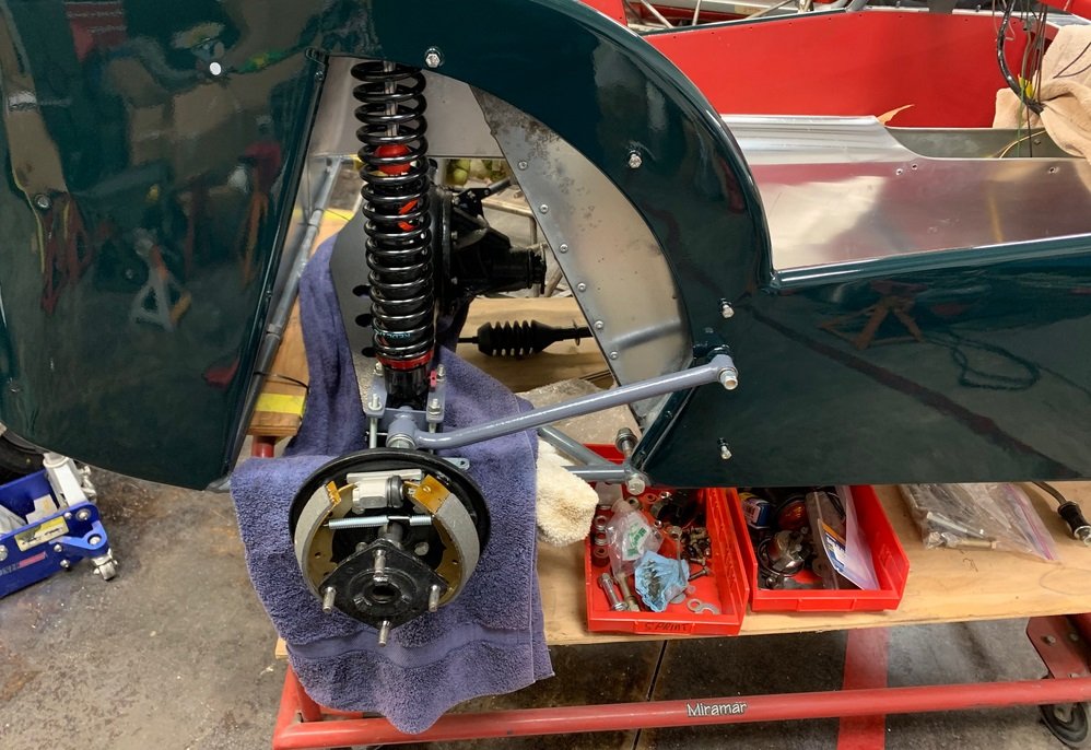
Ditto on a slightly shifted on the mounts yet undamaged rack. I don't think the toe link is bent but it could be slightly. I think one of the control arms are slightly bent and/or bushing damage, with the wheelbase slightly shorter on the left side. Looseness can be difficult to determine with the suspension loaded. -
-
Adjustable length (on the straight, forward end) would be nice for pinion angle adjustment. If you can't find one or a set, new can be made from the old ends or just used as a pattern, with known, good eye to eye measurements. Here is a pic of a good upper arm.
-
Looks good. Interested in seeing how well the leds hold up on cycle wings.
-
It does not appear that removal of the hub from the axle is needed in order to remove the center section on a Triumph TR-10 axle. Looks like the axle and brakes are retained by four bolts and can be pulled together with a slide hammer. The assembly could be taken to a mech shop with a hydraulic press for hub separation for outer seals. If you have any plans for autocross, bigger tires, engine output improvement, or driving faster than 60 mph (4.11, 4.55, or 4.88:1 ratio), consider an axle upgrade/swap. A woodruff key and taper keeps the hubs from spinning on the axles and is a good indication of the torque capacity limitations. EDIT: The axle and hub come out as an assembly: https://www.simplesevens.org/history/t10axle/axlebeebe.htm