JohnCh
-
Posts
3,338 -
Joined
-
Last visited
Content Type
Profiles
Forums
Store
Articles
Gallery
Events
Library
Everything posted by JohnCh
-
Exactly what I needed, thanks! -John
-
Does anyone know the torque spec for the fill plug on a Type-9? I can't find it online or in my reference section at home. Given it's an awkward reach in the Westfield, I'd prefer to use a torque wrench to ensure I don't screw it up. Thanks, John
-
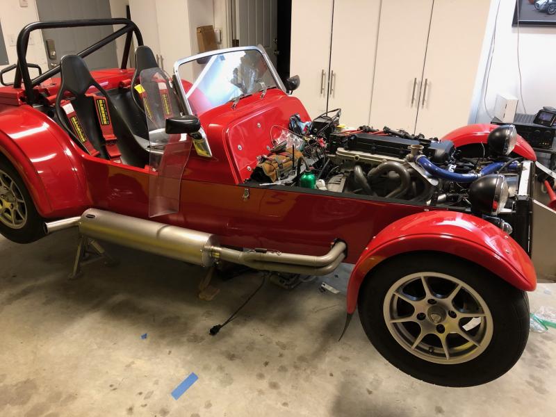
It took 90 minutes, a hoist, two floor jacks, a set of jack stands, and shockingly no swearing (honest!), but the engine is in. Still a lot of work to do before first start, but the initial attempt should happen soon. -John

-
Is it possible to make some kind of cover for the block to hide the unneeded holes and give it a finished outward appearance? Bond a piece of carbon fiber or black painted aluminum sheet to the top? I don't know what the blocks looks like, so finishing the edge of that cover might be tough (route a recess to receive it?) but it might be worth considering something like this if you haven't already gone down that solution path. -John
-
To add to the above, the SVT has bigger valves and redesigned intake ports. I believe the short block adds forged pistons and oiling changes. Stock to stock, the SVT is a big upgrade over a regular Zetec. -John
-
I had a DOH! moment Sunday night. It occurred to me that I never ordered replacement bolts for the pressure plate. After a little digging I was able to secure a set from Massive Performance here in the States which arrived today. Last night I test fit the engine without the bellhousing/transmission to confirm the engine mounts lined up and refresh my memory on wiring and hose routing. Then installed the flywheel and clutch this evening. There are a few more things to do over the next couple of nights, but I might actually be in a place to attempt installation Saturday. -John
-
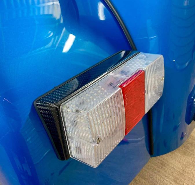
Here is the carbon fiber light block. The copy states they are handmade to order, so my bet is they could supply it without the pre-drilled holes for the standard Caterham rectangular light. -John
-
I felt the same way when I rebuilt my car and went with the Land Rover lights in your last link. I don't have a good picture on this laptop, but this will give you an idea. Obviously this is a Westfield not a Caterham, so some visual differences, but also Westfield molds a flat spot in the rear wing to take the standard tail light -- i.e. no mount needed to match the back of the light with the curve of the wing as on a Caterham. As for housings, I could swear someone did a carbon fiber block for the standard lights that would work. I'll look around to jog my memory. Happy to send you a better picture if it's helpful. -John
-

New owner with a questions for a cross country trip
JohnCh replied to SanderGA's topic in General Sevens Discussion
One advantage of the hood is the ability to close up the car at night to prevent people from trying it on for size in the motel parking lot (yes, it does happen.) When I rebuilt my car down to the frame in 2004, I intentionally didn't install the provisions for the hood despite having a brand new one in the box -- just hated the experience. When touring I use a locking car cover. Something to keep in mind. -John -
New owner with a questions for a cross country trip
JohnCh replied to SanderGA's topic in General Sevens Discussion
I second the half hood and the ear plugs. I've been on a tour with crossflow cars that were tuned for sea level or close to it and we went to 10k feet in that same part of the country. Yes, they ran rich and were pretty stinky, but it was manageable. Given your talking about a much smaller delta, I wouldn't be overly concerned, but if you can acquire some appropriate jets as Andy suggests, that's your best option. Some things to consider when touring in a se7en: plan your route to ensure you can make it between gas stations, pack like you are backpacking, bring lots of water -- between sun and wind you will dehydrate -- and bring some tools just in case. Someone with a Caterham can confirm, but I stow the side curtains in the passenger area when I'm solo and behind the passenger seat if that's occupied. -John -
The Regular Summary of Classified Ads of Se7ens Found For Sale
JohnCh replied to Croc's topic in Cars For Sale
His ad and video serve as the new model for maximizing the sale price of a Se7en. I'm not sure if I found it more interesting that three different bidders were still in the running after it broke $40k, or that all the negative comments regarding the price posted by a Caterham dealer didn't make anyone flinch. Regardless, I hope the new owner feels it's worth every penny once he has the opportunity to drive it hard, and that he joins the forum. -John -
I'd say it's metric given M22 is nearly that size (0.866"), but that thread pitch is really fine for something that big. I've found this page helpful in the past when trying to figure if something is BSP, NPS, or Metric: https://trimantec.com/blogs/t/thread-identification-guide -John
-
This might be too big at a touch under 18" long but I love mine. They also do a 10-50 ft lb version, but I believe it's the same length. Precision Instruments Split Beam -John
-
No progress to report thanks to spending most of the day SUV shopping (yawn). When we returned, I took the Elan out for a much needed, head-clearing blat, but came upon this group just as the corners began 1.5 miles from home. They did not want to move and were in no way intimidated by either the sheer size of the Elan or the angry scream of the revving twincam. I was tempted to try the horn, but it's a Lotus and with my luck it would have released all the Lucas smoke contained in the wiring harness. I'm beginning to wonder if I really screwed up in a past life... -John
-
The ARP values above are from their website for these specific bolts (see link below), so I'm not sure they would provide a different answer. My guess is that from an engineering perspective, 95 ft-lb creates sufficient clamping force, but to Croc's point, SBD has a lot of practical experience in this area with high revving, big power Duratecs. Their approach and slightly higher values are probably what they find best in their builds without failures. 251-2802.pdf
-
Car looks great! Good to see Caterham emblazoned the dash with the model name in large letters so the passenger is clear on exactly what just scared the living hell out of them :jester: Looking forward to seeing this beast in the flesh. -John
-
When i upgraded the cams in 2007, I also purchased ARP rod bolts and ARP flywheel bolts for the increased redline. The flywheel bolts were purchased form Cosworth and arrived in their packaging, but the bolt heads are stamped ARP. After removing the engine back in 2007, I discovered ARP flywheel bolts were already in place. These were the bolts Raceline supplied as part the Duratc kit I purchased in 2003/4, but at the time I didn't notice they were ARP. Since there was no point in replacing the bolts at that time just for the sake of replacing them, I left them alone and kept the sealed Cosworth bolts in a box until I needed them. Like now. I'd be surprised if Cosworth, SBD, and ARP each have bespoke versions of those bolts. Having ARP do something different isn't cheap, and that would mean that SBD or Cosworth thought there was something wrong with the original spec. It seems a stretch. I think I'll go with the SBD torque value, but include an initial lower torque third step to more closely align with the Cosworth approach. It's interesting that both Cosworth and SBD specify multi stages, yet SBD's initial stage is higher than Cosworths final stage. I also find it interesting that the procedure with the lowest final torque value uses no thread locker and the one with the highest value uses the strongest. As for the Loctite 242 vs. 243 conundrum, Amazon made that decision. 243 wouldn't arrive until Thursday, but the 242 will arrive tomorrow. I'm tired of waiting... Thanks, John
-
160F seems awfully low. If working correctly, that would keep the temps in the 150s or possibly lower. The 180F (82C) seems like a much better choice. If you are still having issues after that, Anker has good advice. All fans aren't created equal (current draw is a decent proxy for effectiveness) and keeping minimal clearance between fan and rad core (+ shroud) increases efficiency. Are your temp issues just in traffic, or are you also having high temps at speed? If the latter, make sure you have shrouding that ensures the air entering the nosecone is actually funneled through the radiator rather than around it. -John
-
Thanks guys. I'm sure Croc will be along soon to weigh in on my lack of sanity. I decided to install the flywheel after lunch and researched the correct torque and if Loctite is required. I last did this when the engine was built in 2004, so have no recollection of the process. When I had the engine out in 2007 for the first cam upgrade and to install ARP rod bolts, I also bought a set of Cosworth flywheel bolts (stamped ARP but in a nice blister pack that has Cosworth printed all over it) as an additional upgrade. However, when checking the flywheel, I discovered it already had ARP bolts installed. These must have been what Raceline supplied as part of my original engine kit. Consequently I left them in place and stored the new ones away for future use. This is where things get interesting. The CSR build manual includes torque specs and process for their flywheel bolts, which are presumably ARP like what I purchased years before. SBD also sells ARP flywheel bolts and have a download on their site for their installation. Lastly I checked the ARP site and downloaded their instructions for these bolts on a Duratec. None of them align. Cosworth Torque in 3 stages: 37 ft lb, 59 ft lb, then 82 ft lb There is no mention of thread locker SBD Torque in 2 stages: 85 ft lbs., then 105 ft lbs. Use Loctite 243 ARP: Torque to 95 ft lb. Use Loctite 242 So very different final torque values and although Loctite 242 and 243 are both medium strength, the 243 handles slightly higher temps (360F vs. 300F) and has significantly higher breaking torque (230 in. lb. vs. 110 in. lb.) Torqueing in 3 stages makes sense, but at what value do I stop? I'm leaning towards the stronger 243 and torqueing to 100 ft lb, but anyone have an experience or counter advice? Thanks, John
-
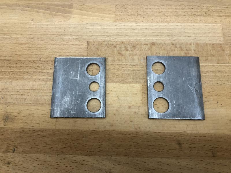
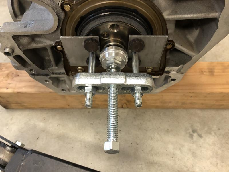
I just read this again before hitting submit and realized it's a lot of long-winded drivel that many of you would prefer to skip. So for those who would rather me just get to the point so you understand the context of the photos and move on, here is the executive summary: This morning I made a tool to install the pilot bearing. Worked great. Took a lot longer than anticipated. The end. And now for the rest of you... Any masochists out there who have actually waded through my website will know that I have a theory called the Rule of Three. No matter how pessimistic I am when estimating how long a job will take, I'm always off by a factor of three. Even knowing that when going into the planning process and multiplying the initial estimate by three to short circuit the process doesn't satiate the gods who control this aspect of my life. It still takes three times longer -- or, in that case, nine times longer than what my original estimate would have been. Consequently I no longer apply that fudge factor to my estimates. Life is too short. Anyway, this morning I had planned a small list of items to complete by ~10:30am: Install the pilot bearing, flywheel, clutch, test fit the engine without the transmission to remind myself where all the wires and fuel hoses need to go and ensure the engine mounts are lined up correctly, and finish installing the AEM WBO2 setup. Easy list, right? Arriving in the garage with a hot cup of coffee, I looked around and realized this place was a nightmare. I needed to clean it up before progressing. Once that was done, and with cup #2 in hand, I began the process of getting the engine off the engine stand to gain access to the back for the pilot bearing installation. More futzing around was done as I looked for the correct bolts to attach the cherry picker to the engine. With that completed and the engine on 4x4s on the floor, the engine holder was removed to expose the back of the block. Looking at the crank and thinking about that little pilot bearing that was finishing up a 24 hour soak in the freezer, I began to have a little trepidation about this step. A little more research was conducted to ensure I knew how deeply to seat the bearing and which end faced the transmission. This brought up lots of mentions of damaged thrust washers from beating the bearing in place. The Cosworth CSR260 engine assembly guide does mention to install it before installing the crank in the block for just this reason. Unfortunately I read that bit after I received the short block back from the machine shop. Given I still don't know if the shop did the assembly correctly, and I could still discover issues once it's back in the car and running, doing something they could then claim was the root cause seemed like a bad idea. I finally came across a guy who used a steering wheel puller to press his bearing into the crank. Hmm. Instead of threading the bolts into the steering wheel, you thread them into the flywheel bolt receivers on the crank. Made sense and I have an old steering wheel puller I could modify. First step was figuring out the size of the new bolts required. Grabbing a flywheel bolt, I had an uh oh moment. They have very fine threads. M12 x 1.0 to be exact, and I needed two bolts at least 60mm long to make this work. Once at the hardware store I confirmed that this is a really oddball bolt size. M12 very fine spec is 1.25 and I needed 1.0. Super fine? Driving home and not wanting to wait a week for McMaster Carr to save the day, I started thinking about other options and decided that there was a way to fabricate a a different attachment method from the leftover 1/8" steel stock I used to make the dial indicator stand, and that would allow me to incorporate the stock flywheel bolts. Out came the hacksaw, calipers, stepped drill bits and drill press. A little while later I had this: The good news is it worked great. The bad news is that I had now nearly doubled the amount of time I had budgeted for the various jobs today, and I had only done one . Oh well, it's still a win. Just a slow one. -John
-
Papak, I jut remembered I posted a photo of the dipstick tube with dipstick sitting out of the bottom here on post #5. It will give you a better idea of the design. -John
-
Thanks, that confirms leaving it alone is the right decision. For the controller's other wires (switched 12v+, ground, sensor signal, sensor signal ground) the Emerald supplied engine loom uses a Superseal connector to make the attachment. Much cleaner and simpler than my old Innovate which had the signal wires directly connected to the ECU plug and the 12v+/- to the chassis loom. The dipstick is the Ford factory blade-style -- same one Raceline supplies (or at least used to supply) with their wet sump. It would work better if the tip was spherical, as this would allow it to more seamlessly make the transition from hose to connector, but I cant' find a good alternative that has a flexible enough tip to also make it around the 45 deg bend of the bottom fitting. Unfortunately the blade tip will hang up when it hits that hose-to-connector transition unless they are in a straight line. Hence the reason for the hose's curved route vs. a straight shot down to the sump. -John
-
My original intent for the oil dipstick's upper mount was to use aluminum sheet and perform a little origami magic to add strength. Unfortunately I didn't have any on hand and was too lazy to make the trek to Home Depot or Lowes, so repurposed an old bracket made years ago from a piece of 1/8" aluminum stock. It's a little dinged up, but after some sanding it's acceptable for a part not easily visible from above. The mount attaches to the engine via one of the thermostat housing bolts. Given that's a low torque fastener, a lock washer was added to (hopefully) counteract any potential loosening stemming from repeated oil level checks. Amazing how much time and effort has been invested to correct an issue resulting from a simple oversight when the engine mounts were fabricated years ago. Fingers crossed this version actually works and is drip free. I finally settled on how to route the wires for the AEM X-series WBO2 sensor. As mentioned previously, they assume it's going into a car significantly larger than a se7en and install a very long wiring harness on the O2 sensor end. I'm reluctant to introduce a failure point by splicing those wires, so have opted to keep them in tact and route them around the front of the engine bay. They can always be shortened later should I determine that's a better approach. -John
-
The article doesn't give any detail on how the 2g was measured. Was it an average around the skid pad, or a mid corner transient on a specific corner on a specific track? Big difference... Remember, a good marketer can tell a lie with the truth. -John
-
I've been having trouble getting in touch with the welder I've previously used, so revisited dipstick placement last night. With a little grinding of material from the alternator mount and re-clocking the fitting at the base of the dipstick where it screws into the sump, I have "just" enough clearance to make this work as-is. With everything torqued, the very top of the fitting and the bottom of the engine mount touch (barely), but there isn't any pressure exerted onto the fitting. I think I'll stick with this for now and see how it works in practice. Next step is to fabricate the mount that holds the top of the dipstick tube in place. I haven't done that kind of work in a while and am looking forward to it. If it turns out ok, I'll post a photo. If not, I'll simply mention it in passing The gasket for the oil filter adapter arrived yesterday, so that's now fitted, and the O-rings for the DTHTBs also arrived and will be test fit tonight. -John
.jpg.248dff64019f5a04306708d733ec8a42.jpg)

.jpg.743c9d25c823d845413937072031a5dd.jpg)