MV8
-
Posts
2,303 -
Joined
Content Type
Profiles
Forums
Store
Articles
Gallery
Events
Library
Everything posted by MV8
-
You can use bicycle inner tube, the seal the more modern cats use in the video (spacers are in the video also), or butyl. Sealing isn't critical given the gaps around the frame, doors, etc.
-
I remember the svx. Interesting car. I remember solar cells in the roof to keep the inside cool when parked? The bolt through the timing cover screws into the block or is it only secured to the cover? If you take some pics of that I can probably come up with a solution. The speedo cable end fitting or drive adapter may be missing a sealing washer and/or o ring.
-
There seems to be some confusion. A rubber extrusion goes between the bottom of the screen (engaging the lower frame in the groove shown in your picture above) and the body/cowl/top of the dash board (much like an mgb windscreen). "Mastic" used to glue in modern windshields would be far too strong an adhesive and very difficult to separate and remove later. The glass is smaller than the opening in the assembled frame by the thickness of the steel inserts which provide clearance in the top frame for top snap hardware (so it won't hit the glass) and locks the ends of the lower frame into the upper frame. The lower steel attaches to the lower frame with two screws on each end but it looks like the screws were not installed based on your picture showing the threads.
-
I wonder what the question was. Not enough data imho.
-
The rubber extrusion is between the frame and the cowl, similar to an mgb. The steel looks fine and can be cleaned with "metal prep" phosphorous from home depot and diluted with water to spray on or let it sit in the fluid, then wire brush. The threads should be chased with a tap, then the parts cleaned with acetone and aerosol painted. Rustoleum "professional" aerosol and "heavily rusted metal primer" are good paints for this.
-
I for one appreciate the detailed deconstruction processes. I believe the steel in the lower windscreen channel is original. The tapered, lower corners of the glass don't have much strength and can break easily. The steel locks the lower channel into the upper to maintain alignment without relying on the glass. Is there anything inside the upper channel to ensure the top hardware does not screw into the glass? Another option on the glass sealing is to use butyl rope available at home improvement stores. This is used to assemble plastic head and tail light assemblies on production cars. Treat the rope like playdough and roll it into the thickness needed to fill the gaps and extrude a bit when assembled, then rub off the excess. The problem with butyl is it will shrink and harden after a few decades. Not a problem for light assemblies that can be warmed with heat guns or better yet, placed in a 150f oven for a half hour to soften the butyl but a glass screen is not tempered and if it fit in an oven, the differential expansion of the aluminum frame may shatter the glass. Glass is cheap though; just two layers of regular residential window glass, laminated together. Just need to supply the frame or cracked original glass to the cutter. They will also chamfer (wet sand) the edges.
-
Hooray! The maddening part is not offering full schematics to anyone anymore.
-
Thanks, I was thinking about a zetec with a single coil pack. Ralph, there should be a pin in the single connector at the back of the head that connects one lead of each coil together. This pin should have close to battery voltage with the key-on.
-
If the head light housing you have is for a 5-3/4 bulb, the led assembly is only $32. Beats $175 each. https://www.ebay.com/itm/363665792743?hash=item54ac2b9ee7:g:TEgAAOSwZm9hXX~k&amdata=enc%3AAQAIAAAAwLdayXFEh1bxKAnP6Z8%2BWdBm12xtL9rsB41D3jgHcv0wC%2FyhAiUPlQoIdfv7ZQCovSeGIgEh6ygF%2BdEt4u6ikJIUbHCoOBLUYNb467XFLQeuJnzlB0M73W5MjNniepjwaD4Pt%2BywQ%2FN8Q9BJubTpbRKRRn2qvqVoYD%2F%2BaECICMIHJbnXaY7D8%2FI7VIw4XkNZDGGYB8xeGCgUVr%2B8fA2RJGxxN1vIy%2FdANPnJXW9INo951Nn470OZo5h0cfksk21qow%3D%3D|tkp%3ABk9SR4CyzsSYYg&var=632889802795
-
Bicycle innertube. Mens 26" tube, cut out the valve (no longer a hoop), split with a razor or scissors (no longer a tube). These tubes are folded in a box so cut along a fold seam to keep from making a spiral or shifting cut line. The cut does not need to be perfectly even as the final step is to trim the excess from the assembled windscreen with a razor. No glue/sealer mess. There is an extruded bottom seal at the cowl. I'd look at year one or other restoration site for '60s mustangs. They may sell a similar or same material by the yard. I'd be concerned about a krinckle paint that could be difficult to touch up evenly. A scrim back marine vinyl on a perfectly smooth, sanded panel and contact cement or weatherstripping adhesive would work well. For a padded panel, headliner foam is added in between and a 3m spray adhesive is used that is safe for foams. Use clothes line clips to glue the 3/4 inch overlap around the panel. Multi-slit corner overlaps around the panel edge radius so it will lay flat. Don't cut out the corner overlaps.
-
Thanks John. Even better. Is there an add-on security key fob system that disables the efi but allows cranking? Ralph, also check for key-on bat voltage to the middle pin on the unplugged coil pack connector. Does anyone know if Cat uses the sbd harness? Just a four pin interconnect to the cat chassis harness?
-
Unplug the TPS, key on, check for 4-6.0 volts between any TPS plug terminal/pin and ground. Yes/no? This is a check for what's called Vref or the basic power level provided by the ecu to several sensors to provide an output to the ecu on a different terminal/pin. By having the ecu provide the voltage, it ensures it will be consistent. Also check the terminal on the opposite side of the terminal that showed 4-6v. This will be signal return to the ecu. Check for voltage between the battery positive and this pin, key on. Is this voltage within 1 volt of the battery voltage? Unplug an injector, key on, check the voltage between either pin and the negative battery terminal. What is the highest voltage? Does the ecu have a part number? How many pins does it have? I expect it will have 104, 122, or 150 pins. The battery voltage should be at least 10.5v for these tests without engaging the starter.
-
A DPST switch. Four terminals.

-
I suggest swapping the main switch for a dual pole to isolate the fan and pump buss from the other loads/main buss that do not have a parallel path to power that can back feed. However, the positive leads from the fan and pump that go to the main power switch for the car can have diodes in series and with the diode stripe toward the fan and pump. The diodes need to be sized (watts) to handle the full fan current with no relay. There is still some reverse current flow commensurate with the diode size. Much better to swap the switch or use standard relays with the existing switch gear.
-
Less likely to do additional damage testing unknown wiring with resistance (and the battery disconnected). Never too late to take it to someone who can troubleshoot with very limited information from the mfg. Summer's half over already.
-

Caterham A Frames - check them as part of your annual maintenance
MV8 replied to Croc's topic in General Tech
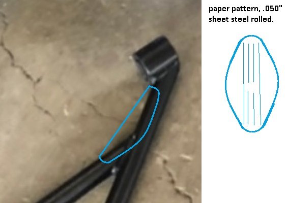
I can see why it failed this way (I also investigate GA aircraft accidents and approve modifications). The sudden change in cross section outboard of the cross bar weld ensures flexing occurs in this small length of tube instead of the load being spread evenly along the length of the arm. Typical gussets could be used (one on each side; never down the center of the tube) but a better way and typical of aircraft tube frames would be to use .050" sheet steel cut from a mocked up kraft paper pattern (cereal box works well). This will help spread the load.
-
Here is one I saw at a LOG event in BHM many years ago.
-
Looking at an early seven schematic, the fan is in parallel to the ignition switch. Green speedo wire is for switched/keyed power (white wire) and red/white speedo wire goes to instrument lights (red). The gps reciever is controlled by the gps harness white wire to the speedo. Is this your harness? Where did you make the connections?
-
No doubt taping works and no need for it now, but I just found "heavy builder paper" at HD in a roll, 3'x.061"x166' for $18. Used to protect laminate and hardwood floors during construction. The coated paper is also used for roof underlayment. I can think of a number of uses for that.
-
By making it a tight fit around the filter, that still leaves plenty of material to open it up for a scoop (like on Voyvchander's car), with room for engine movement/rocking under load plus a little forced air induction. Where did you get the big sheets of kraft paper/chipboard? How heavy/thick? That material in layers would work well as a base for making thin, upholstered panels such as around the tunnel on older cats.
-
Can't see mounting detail from your pics. It looks like the mounting bracket stops at the wing outside edge versus extending into the wing above the tire. If that is the case, the wing should have vertical ribs or gussets above the tire at the mounting bracket attachment but I expect they do not. Looks like they just mount to the outside, relying entirely on the flange of the carbon layup. What does it look like inside the wing? I expect a reinforcing strip inside sandwiching the carbon at the mounting point would cure this.
-
Early Seven hand brake info: https://www.caterhamlotus7.club/forum/techtalk/under-dash-handbrake-missing-hardware
-
Using the 2015 420 assembly guide engine harness layout (no actual schematic), BY11 = GND, WR73 = start SOL, WO = B+ in run/start.
-
It looks like the hand brake loads the end of the spiral cable housing, with the cable end fixed, with adjustment at the tee where each wheels brake cable come together near the axle.
-
Snap clips could be added to the dash for a custom tonneau cover that has a zipper down the center so the driver can fit while leaving the pax side installed. Keeps the water out to a degree. With a lot of sun or rain, a jeep type tonneau is practical. Uses straps at the back and snaps to the windscreen. I saw one on a birkin.