MV8
-
Posts
2,303 -
Joined
Content Type
Profiles
Forums
Store
Articles
Gallery
Events
Library
Everything posted by MV8
-
Baah, you guys are waaay off. It's the fella with the most unfinished projects.........
-

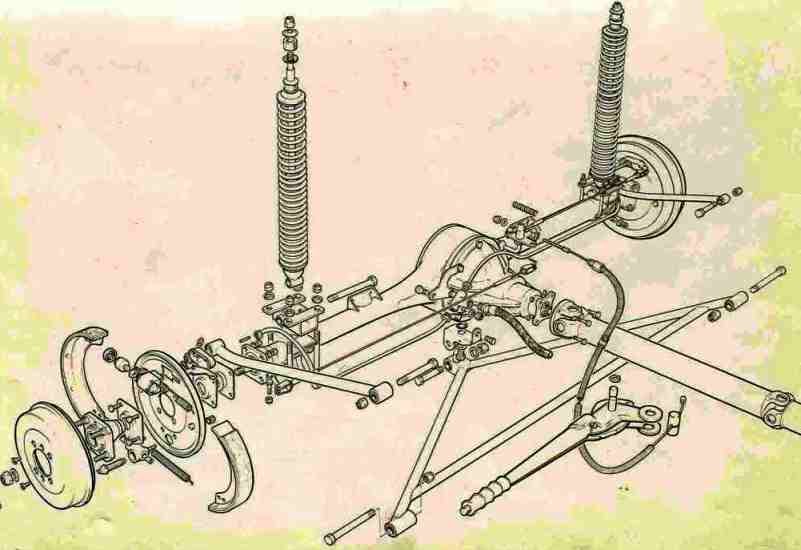
Caterham A Frames - check them as part of your annual maintenance
MV8 replied to Croc's topic in General Tech
Thanks for the drawing. No need to change that to prevent bind on the S1 if the swivel is kept greased. Do you have a good drawing or photo showing the swivel/ball assembly on an S2? This is the best photo I have.
-
Cars can be brought in for a period of time. If not shipped back out, they are tracked down and destroyed. I think foreign diplomats can bring in a car too. The State Department seems to do it's own thing, rules and regs notwithstanding.
-
The transmission is usually built into the bike engine case. Most any rear end can be used if it turns the right direction for the bike drivetrain or is flipped and the vent moved. Reverse options, charging capacity, gearing, etc. There is a lot to know about engineering and regulatory requirements if intended for road use in your area. Depending on what you want to do, a bike drivetrain may not be the best choice. https://www.locostusa.com/forums/viewforum.php?f=10&sid=e097e6e39b96814ff313de5e1f6fbf0a
-
Caterham A Frames - check them as part of your annual maintenance
MV8 replied to Croc's topic in General Tech
That would make a good chassis brace, adding no un-sprung weight. It could also be threaded on one end to eliminate the need for shims. A telescopic fwd mount torque arm with standard trailing arms would work well and fit but obviously not for an original seven. -
http://clarkbrothers.net/right_angle_drive_adapters.html Probably about $200 but whatever ratio, rotation and ford fitment needed. Ford has been very good about keeping the same basic speedo drive system dimensions through the '90s but I don't know about a '62.
-
https://www.treadstoneperformance.com/acura-rsx-k20-k24-turbo-manifold-on-backorder/p103913
-
A three terminal tps can be wired to ascend or descend with opening depending on where the leads are connected, just like any three lead potentiometer. It depends on the wiper versus the reference. Obviously CAT flipped the input and their software (to be proprietary/different I suppose) is made for that. I'd start with setting the warm idle bleed and timing, then adjust the sensor for the necessary voltage at idle. I know nothing about your idle air circuit system, software or any instruction but this is basic.
-
You can drag the stick figure over to see in blue where he can be dropped to look around first person. https://www.google.com/maps/place/Gwynedd,+UK/@52.9132899,-4.0996919,205m/data=!3m1!1e3!4m6!3m5!1s0x486434b66c1c0fed:0xecce1b0314ace6fc!8m2!3d52.9277266!4d-4.1334836!16zL20vMGR0NWs?entry=ttu
-
I'd run either plug or the standard, colder BCP7ES plug with an .044" gap. It sounds like your firing order may be off. For the timing, if there are no timing marks other than tdc, I'd add a 10-12 degree btdc mark and adjust at warm idle to align with the pointer. If there is no 10btdc mark, measure the damper od, draw a circle on a piece of paper that od with a compass, make a mark to serve as tdc (doesn't matter where on the circle), use a protractor to find 10 or 12 degree cw from the tdc mark and mark that on the circle. Use the compass or dividers to set the distance. Place the compass/divider on the damper and mark it 10btdc (cw of the tdc mark). A black permanent marker works well enough or add a piece of masking tape along the damper for a contrast to the mark as a temporary reference. They make degree tapes for this but the damper od must be correct for the tape. Use a timing light to fine tune any static checks of the distributor rotor alignment.
-
There are some special head gaskets that could be used to raise compression (multi-layer steel) or seal better (composition Group A gasket) but I would probably fit a standard Felpro for a pinto engine (after comparing to pics of the felpro). May want to put that off until you know what hard parts may need to be shipped to repair/rebuild the head. I'd pull the valve cover to look at the lobes, compare valve height at tdc (dropped seat?sticking open?) and look for a broken spring. You could also add a little oil to the low cylinder to see if it goes up a lot, indicating a bore/ring issue.
-
Crossflow Cooling System -Overflow Tank or Expansion Tank
MV8 replied to KS7's topic in General Tech
When all things are sized, filled, and operating as they should be, an expansion tank can eliminate the need for recovery but that isn't realistic. Pressures typically increase above normal operating pressure right after shut down when flow stops. Assuming the expansion tank is big enough for the system to be half full, the air is compressed with normal use when running. The safety relief valve should be the same or close to the original PSI to help prevent radiator, heater core, or heater valve damage. The safety valves outlet barb needs to be open to loss or a recovery/overflow tank, not back into the closed system. The only real options to the radiator cap are to be made to fully recover (outer rubber washer) or not and sometimes if there will be a vacuum relief valve (spring loaded center washer shown in the pic of a cat cap). Just having a recovery tank and rubber washer in the cap is not an unreliable system. -
I use Meguiars plastx. It is at most auto parts stores. A few drops on the lens and my thumb to rub it in swirls all over the lens, then wipe it off with a paper towel or less abrasive rag. Lasts a long time. One bottle should last forever.
-
What are the specs for that engine (cam lsa, intake duration, compression ratio)? I'd guess 120-160 psi within 10% or each other for a good, well used engine. For a given duration and lift, a smaller lsa equals earlier intake valve closure for numerically lower idle vacuum and higher cranking comp.
-
TEM, have you cleaned out the tank bottom yet? The borescopes typically have a button for taking pics and variable brightness thumbwheel. Maybe post some pics of the tank inside and out? Is it like the S4 but shorter in width to hold about 5 gallons? A new pipe can be brazed in if needed by cutting it out with a rotary file and needle nose pliers to pull it out if not attached inside. A new pipe from 5/16 brake tube can be inserted fully to hit the bottom, pulled out a 1/2 inch, then cut and flared while still straight before bending, then brazing or silver solder to the tank wall. If the hole is too big, fit a washer. I'd be tempted to add a 1-1/2 inch length of 2 inch exhaust tubing to the bottom for a g force defying sump and a brake pipe fitting for the outlet.
-
Is the pipe attached inside the tank or is it only attached where it passes through the tank wall?
-
Place a small sample of the goo you already removed in a container, then test with different acids to find one that will visibly react. If your funnel is not higher than the pipe inlet inside the tank, it won't siphon/flow even if you soften the clog. That's why I suggested inside the tank with the entire pipe below the fluid level.
-
There are many names for the borescopes, endiscopes, etc. Make sure the focal length is at least a couple inches at a minimum. Some are made for a shorter length to where you can't see anything in focus unless it is extremely close to the lens.
-
You could fill the tank with a sufficient amount of some acid (like drain cleaner), position the tank so the fuel pipe inlet (inside) and outlet are both below the acid level inside, just above a plastic basin where it won't splash when it becomes unclogged, and let it sit a few days, waiting to see if it will leak out (desired result). Wash it out, then use a small air compressor and rubber tip nozzle to blow into the outlet pipe and wash again. The pipe can be replaced or a new fitting added to the bottom by someone who has experience brazing and welding on used fuel tanks (I do). Here is a fellow building a new tank for an S4 (starts around 5:50. Hard to find any pics of any steel tanks).
-
The foam is soft when new, and can be squeezed in. It doesn't have to be one piece of foam. I am not a fan of foam in the tank. Use a magnet duct taped around a stick or ruler to get the hardware out. If you don't have a small pressure washer, consider taking the tank to the car wash after soaking for a day to soften things up. Radiator repair shops had tanks they would also use for fuel tank cleaning but I think they are all gone now.
-
It is a special rivet. Takes a special rivet gun. Some shops tap for a flanged, socket head plug with an o-ring or gasket.
-
Delete. I see tps swing is also reversed on knifey's.
-
The foam is something people add for racing instead of a custom tank with baffles or other methods to ensure the fuel pump pickup tube stays submerged in fuel when cornering.
-
FOR STEEL TANK ONLY, I'd use a lot of lye and water to sit, then flush, then strong phosphorous if there is rust. Muriatic would do both at the same time but very strong, nasty stuff that can burn and blind you. It's good there is a stand pipe in the neck to help prevent overfill/provide expansion space. Usually, there is a small hole in the side of the pipe just inside the top of the tank but there may not be on these. You can make a finger strainer to supplement the filter(s). Use galvanized or copper mesh (hardware cloth if you can find it small enough) to make it easier to solder the edges. Roll it 3/4 od x 3 inch and solder the end and most of the side seam, then squeeze the end down to the pickup tube od to solder or hose clamp on with an inch hanging off the end. Stainless can be soldered but it takes treatment with an acid for the solder will wet.
-
Help! I can't decode my Locost VIN to anything!
MV8 replied to Bentwrench's topic in General Sevens Discussion
Congrats! Nice looking replica. The bonnet is unique to this kit, but I can't remember where I've seen it before. Maybe it will come to me. A vin decode probably won't help if they didn't sell kits here, but try the NHTSA decoder using the full vin. I guess original registry in the UK was around 33 years ago and the kit likely older than that. It would be nice to see more pics such as the axle, front suspension, interior, engine bay, etc. There may be clues.