MV8
-
Posts
2,303 -
Joined
Content Type
Profiles
Forums
Store
Articles
Gallery
Events
Library
Everything posted by MV8
-

Duratec fuel pump standard Ford or special Caterham item?
MV8 replied to KnifeySpoony's topic in General Tech
I think the escape/tribute pump assy will stick up higher by a half inch or so than the focus pump due to the fittings. I've not used any carter other than the gerotor pumps made for carbs. Those have been excellent. -
Also, check the running voltage at injector #3 compared to the others (wiggle the wires while checking for an intermittent connection). If that is lower than the others, the cylinder would be lean by comparison.
-
Duratec fuel pump standard Ford or special Caterham item?
MV8 replied to KnifeySpoony's topic in General Tech
Rock just shows domestics. The focus was not offered here until 2000 but I expect the pump is the same as a euro 1998 focus. For those looking for a return line pump assy that SHOULD fit the cat tank opening and depth, look at the Ford Escape/Mazda Tribute pump assy. -
After some digging (topic not under member rides and 35 pages with no mention of the key word "Flir", I found your post with the pic showing the thermal of the exhaust with #4 not appearing to be firing at all. This one is much more subtle at a 75f difference.
-
Duratec fuel pump standard Ford or special Caterham item?
MV8 replied to KnifeySpoony's topic in General Tech
2000-2002 Ford Focus. The complete assemblies are $50-100 and the pumps by themselves are $10-100. Carter and delphi are good brands. https://www.rockauto.com/en/catalog/ford,2001,focus,2.0l+l4+dohc,1385524,fuel+&+air,fuel+pump,6256 -
How do the plugs look? Compression test, move coils and plugs around. Oil consumption dilution on #3 rings can slowing burn rate so it is delayed in to the exhaust, #3 exhaust valve lash too tight, soft/broken valve spring strong enough for compression test but not so much driving allowing the exhaust valve to float so reduced heat xfr to the valve seat, increasing heat through the valve to the guide increasing sticking, etc. Maybe you need to work on the other three cylinders.
-
I agree, but that is the spec from CAT for a 2014 (chosen out of convenience). Here is an excerpt from the 2014 assembly manual and it applies to all 2014 seven model with adjustable spring seats: "5.9) Cars fitted with adjustable damper platform Cars fitted with adjustable damper platforms need to be adjusted to achieve the optimum ride height. This is done by lowering or raising the height of the platforms on the threaded sleeve. It is essential that this task is carried out on level ground. NOTE Lowering the platforms will decrease ride height, and raising the platforms will increase ride height. For the best results the ride height should be set with the driver in the car and fuel in the tank. 1. Start by adjusting the front dampers to achieve a minimum distance of 150 mm (this can be increased for road use to a maximum of 190 mm) between the ground and the bottom of the lower chassis rail, where the rear leg of the front lower wishbone exits the side of the car. This measurement should be the same on both sides with the car loaded. 2. Now adjust the rear dampers in the same manner to achieve a height 15 mm higher than the front, measured to the underside of the lower chassis rail immediately in front of the 'A' frame mounting point. NOTE Adjusting the rear may have an effect on the front therefore it is good practice to check between front and rear several times during adjustment 3. Once the desired ride heights have been set ensure that the platforms are locked together to avoid movement." GC spec from Lotus has been 6" to the rails but the sump is lower than the rails and road testers likely considered sump clearance to be GC and without a driver onboard. Tests I've read between '57 and '71 indicate 4, 5, 6.2, 3, and 6.5".
-
Full of fuel and with driver, the rear GC should be 165-205mm with the front 15mm lower than the rear. The adjustable lower seats may fit the standard bilsteins. The bump stop donuts wear too. Are the 120# springs progressive?
-
Oh no, I meant what I said, referring to placement in relation to the center line, not seating position. Not the consensus view on the acronym obviously, but you understood so I call that a win. Driver placement does not determine the head light type.
-
Polished .048" 304 6x12", $25: https://www.mcmaster.com/9785K232/
-
Consider bedliner coating the front of the new .050" steel guards after painting.
-
Useable? yes. Better than DOT approved? A subjective yes. Meeting inspection requirements? Probably not due to lacking DOT marking on the lens.
-
Stop Knifey, you're gonna make me blush.... You don't have tariffs when buying a focus pump domestically. If the fuel system is upgraded with an adjustable regulator and return, it is possible to set it up to where the existing tune does not require a retune ($$$). If I could not find out what the intended operating psi is (the result of the fixed pwm provided by the ECU), I would set the fuel psi to 45, run the car until warm, unplug the idle air control valve (IAC) if equipped, then adjust the psi slowly to peak idle rpm, plug it back in to drop the rpm, repeat a couple times, then add a enough psi to drop the rpm slightly without the iac plugged in. If using a wideband to adjust the fuel psi, I'd shoot for around 13:1 idle, mid-range 14:1 part throttle accel, mid-range 12.5:1 wot, part throttle steady/cruise 14-15 from 2-3000, 15-15.25:1 from 3000 to 4000. Ball-park compromise as it is unlikely you will be able to hit all these with fixed, unknown maps.
-
I appreciate your candor. Maybe this will help: https://en.wikipedia.org/wiki/Left-_and_right-hand_traffic
-
The pump isn't worn out. It is running at less than full capacity (i.e. running part-throttle in the CAT). In a focus, the ecu would sense the pressure loss, then tell the pump drive module to increase pump output. The CAT also can't compensate for any change in restriction such as a partially clogged fuel filter so you might change that as well. So many ways to address this but I understand the concern about fuel system changes. A replacement focus pump (from CAT or anywhere else) is not an exact copy because the required output tolerance is wide due to the ability to "throttle" the pump output. For example, you could replace an engine that made 200hp with one that produced 190 at the same rpm because you can throttle the engine to produce the speed you want to go. The CAT has a fixed throttle for the fuel pump. Try a $50 focus pump and see if your problems change.
-
So, as the pump wears, output is less and less like any pump. With this setup, the wear results in less and less psi because the pump drive output is fixed by the CAT ecu. If there were a regulator and a pump running full voltage/output, it would maintain psi until the pump was no longer capable AND the regulator was not bypassing at all at high rpm and WOT. You can't just add the FRP to the rail or fit an oem rail becuase you are not using a ford ecu. Also, as-is, you don't get the benefit of return flow to dump in the bucket when cornering. A bandaid would be to bypass the pump drive module for a full 12vdc to the pump, then swap the internal regulator spring for a lower pressure (whatever a new pump puts out key on-engine off for the CAT tune; 45-55psi?) with no return and performance should return to original. You could also just replace the pump assy but the life will be shorter than modifying the original as described above. Another alternative is to replace the pump assy with a return line type so no drilling to fit a return to the tank. The 2001-04 Ford Escape/Mazda Tribute looks like the best bet but would require a new electrical connector and the gauge ohms may not match up with a focus. What do you want to do?
-
I thought this sounded familiar. Not using sensors and the CAT ecu is running a fixed pulse width through the pump drive module to drive the pump at a fixed output with no feedback and the regulator is a safety set to 90 psi it will never see with the CAT setup. It appears to be a 2000-2002 domestic ford focus pump assy. See catmando's post here on page two:
-
I'd add a pressure gauge to the port on the fuel rail then run the engine to check for variation between 35 and 70 psi.

-
Ok, it is a mechanical regulator returnless system. It is a basic 90s fuel pump system with a bucket to help with slosh. The shiny piece in the middle is the regulator with a ground wire to prevent static build up from the fuel pumping through. It is not as good at maintaining pressure as a return system with a regulator on the rail, but your issue seems to be slosh. The flow out of the regulator could be better directed down into the bucket with a .050" sheet metal baffle at a 45 degree angle in front of the reg outlet, clamped on to the regulator with a heater hose worm gear clamp. Simple to make the baffle with snips and pliers. The float arm that provides the level indication is the only thing that could come loose in the tank and would have no effect on pressure loss during cornering. The bucket is spring loaded against the bottom of the tank when the retaining ring is installed. The three tab snap hose connection is typical of euro fords.
-
If you have a ford fuel pump driver module near the tank, then it is an electronic returnless system and has an electrical fuel rail pressure sensor. If you do not, then the system is a mechanical returnless system with a fuel pressure regulator inside the tank next the pump. A mech sys remote regulator is not as responsive as one mounted to the rail at the injectors. A returnless sys is not as responsive as a return sys off the fuel rail but an electronic returnless should alter injector pulse width based on the pressure sensed by the electronic rail pressure sensor and how long it stays low. A pic of your pump assy outside of the tank would help to confirm regulator placement. I suggest adding a mech regulator near the rail on the firewall with a 1/8npt port for a gauge or electric pressure sensor you can monitor while driving. You can adjust the reg so it has no affect and serves only to provide a pressure indication. If you want to add a return and eliminate the in-tank reg, your half way there already. The original type pump assy can be reused with the mech reg removed and a bulkhead fitting added to the top of the tank to dump return fuel on to the pump inlet but it would be better to swap if there is a return bucket pump assy that will fit the opening. The return should have a tube extending inside the tank to near the bottom to reduce splash/aeration of the fuel.
-
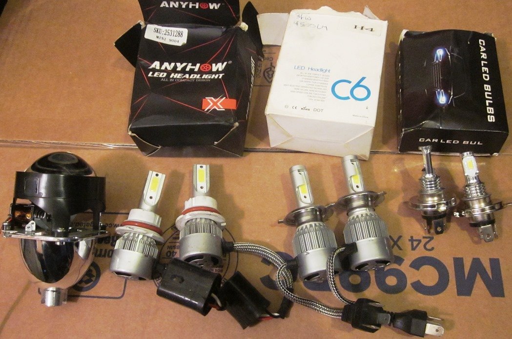
I received the lamps today. Fwiw, they are Ecode 6 (approved for Belgium/right-hand drive) and not DOT but it should not matter unless you have inspections for that sort of thing or you are building a car for the initial inspection for tilting. Also includes H4 bulbs. For cars without relays, it would be worthwhile to install this harness. One, three-prong headlamp socket on the car is used to control the new circuit. It plugs into a male socket on the new harness. There are two eyelets in the harness for battery power and a ground. There is eight feet of harness between the headlamp sockets so it should be plenty to route between the buckets without cutting.
-
I prefer to lubricate all hardware for some corrosion protection and antisieze but the torque spec complicates things. https://www.engineeringtoolbox.com/torque-lubrication-effects-d_1693.html When a bolt is lubricated - less torque is required to achieve bolt axial load or tension. Reduction of torques for lubricated vs. dry bolts are indicated in the table below. Lubricated Bolts - Reduced Torque Lubricant Torque Reduction (%) Graphite 50 - 55 White Grease 35 - 45 SAE 30 oil 35 - 45 SAE 40 oil 30 - 40 No lube 0 Example - Reduction of Torque when Bolt is Lubricated The maximum tightening torque for a slightly lubricated 1" Grade 5 coarse bolt is 483 lbf ft. Dry bolt torque is approximately 30% higher - or 628 lbf ft. Tdry = (483 lbf ft) (1 + (30%) / (100%)) = 628 lbf ft If the bolt is lubricated with SAE 30 oil - the torque compared to a dry bolt is reduced with approximately 40%. TSAE30 = (628 lbf ft) (1 - (40%) / (100%)) = 377 lbf ft Note that if torque specified for a dry or slightly oiled bolt torque is applied to a lubricated bolt - the bolt may overload and break.
-
I have catalogs I use to ID and cross reference wheel studs and nuts. There are often a variety to suit or upgrade an application. A stud should be removed to measure with a dial caliper to ID a replacement. Provide thread pitch, overall length, unthreaded shoulder length, and knurl OD.
-
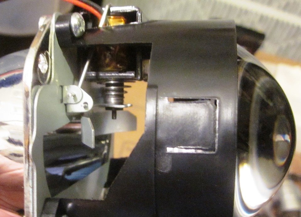
These are 9004 and H4 leds. Note the large finned heat sinks and internal fans on the higher output leds. The mounting ring can be rotated to adjust the led clocking. The retrofit projector clamps into an existing oem head light opening and requires a small led lamp due to the small opening available. Note the servo door that blocks part of the beam and is opened for high beam.
-
https://usa7s.net/ips/topic/12327-led-headlights/#comment-145520 Outbound's headlights are not conversion to a replaceable bulb or led. When they fail, you buy another to match and may only be offered as a set at that time. Not an issue imho considering how little these cars are used in the dark. For reliability, due to the confined space available to fit led chips most leds made to fit a head light bulb socket have integral fans on the back. The seven bucket makes this more critical as there is zero airflow available at the back of the light housing inside the mounting bucket. Select an led equivalent to the bulb watts for higher reliability and less glare in the eyes of other drivers. Glare can be from excess output but also from the direction the leds shine compared to the bulb the housing was designed for. The leds usually have an adjustable clocking in the housing to get the best balance of glare and distance. A light can appear very bright yet the distance compared to a halogen is much less. Some led conversion lights have zero discernable difference when switching between high beam and low beam. All these things brought me back to a quality halogen. A DOT stamped one piece led conversion for a 6024/6014 application should be the best as far as leds go with the fewest issues aside from being a throwaway assembly when it fails. The best replaceable bulb conversion housing is a projector with a servo door inside that blocks part of the beam for low beam situations. They make kits for converting oem assemblies to this but I've not seen this in a 6014/6024 H4 conversion; probably due to insufficient space for the kit. These toyota housings should have better designed internal components and lens sealing compared to just installing a throwaway 6024 halogen and can be used reliably with a limited output led. I can post some pics as I have examples in hand of everything.