All Activity
- Past hour
-
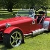
 It's not too late for them to paint the wheels white!
 -
 Apparently most of the senior builders/assemblers went to this to maintain all the 22 cars, and mine that is in build isn't progressing as quickly because of it! Drat! Super cool though, maybe they'll get some awesome press out of it.
 - Today
-
 Just received a Caterham Bulletin that in part says:
-
I always wondered why you would need a quicker than standard rack. As a non-autocrosser that makes perfect sense.
-
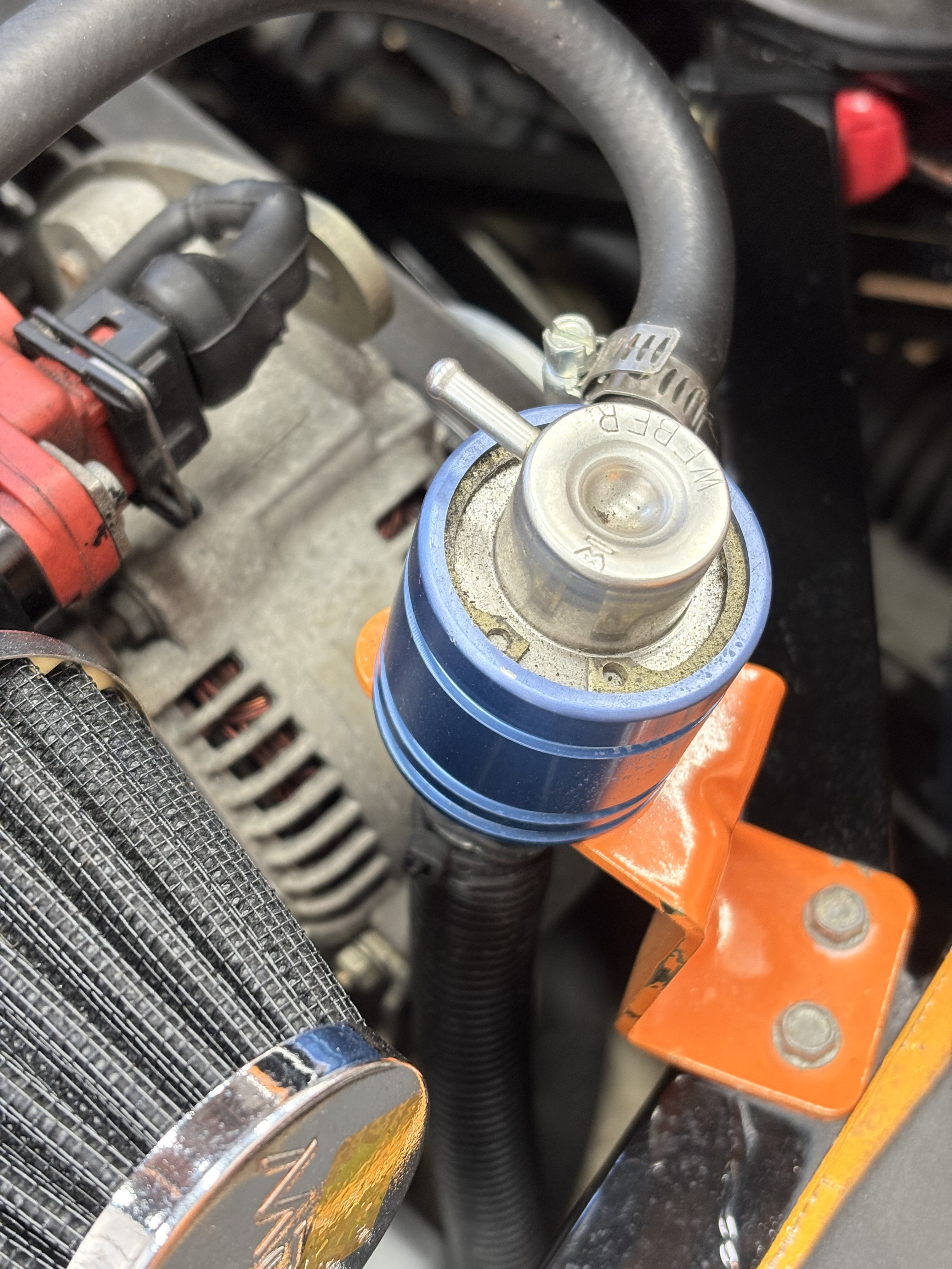
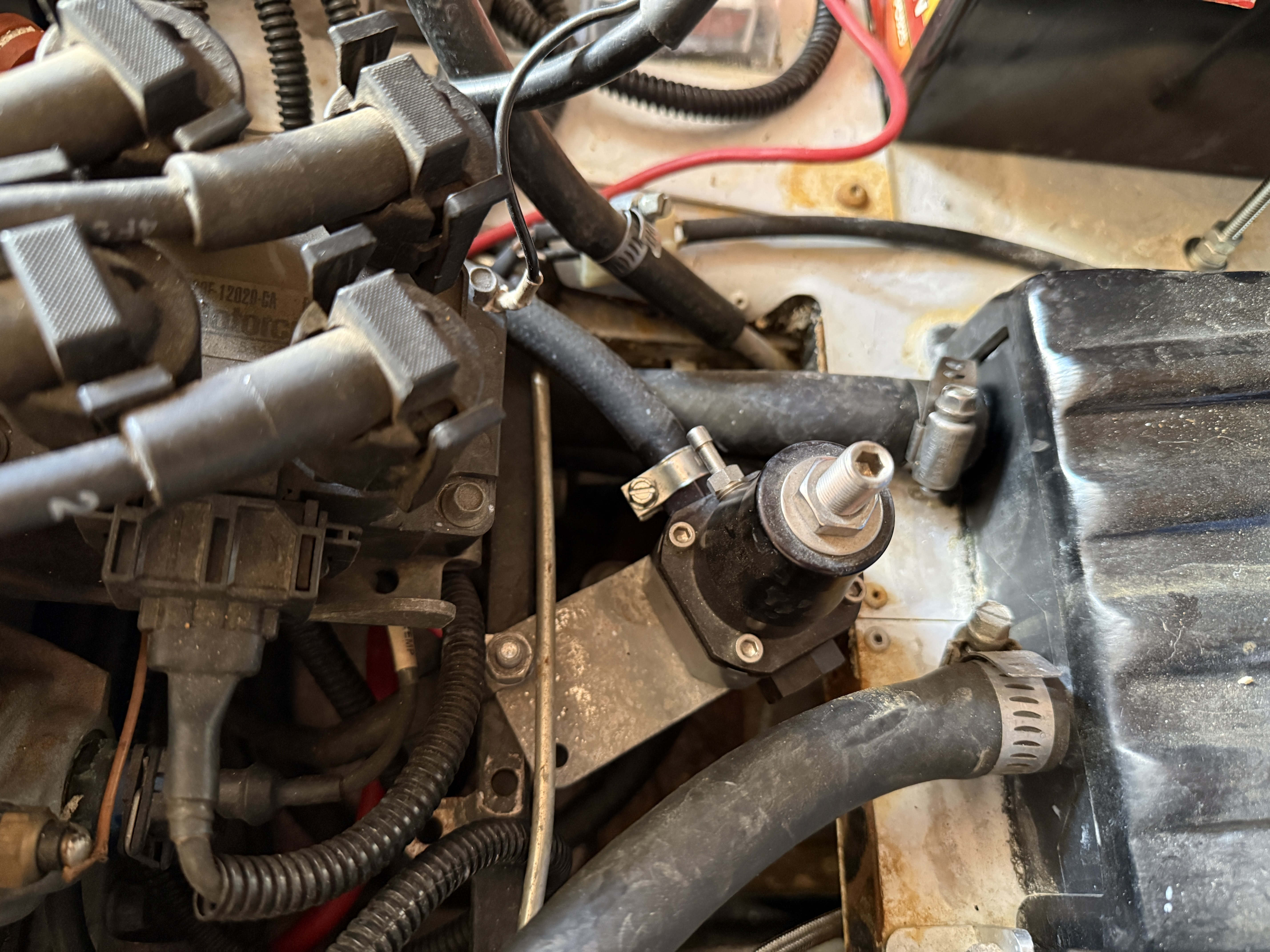
That's to hook up to a manifold vacuum line/fitting to automatically adjust fuel pressure by throttle opening (manifold vacuum). In general terms, high vacuum @ idle = lower FP, low vacuum = higher FP. Not typically used on our setups. I put a cap on mine just to keep any potential debris out.
-
We autocrossers are dealing with smaller-radius turns and elements that change direction more-quickly than in road courses. I knew a guy who traded in his "Magnum" Ferrari on a new Nissan Z-car because the Ferrari steering was impossibly-slow for autocross.
-
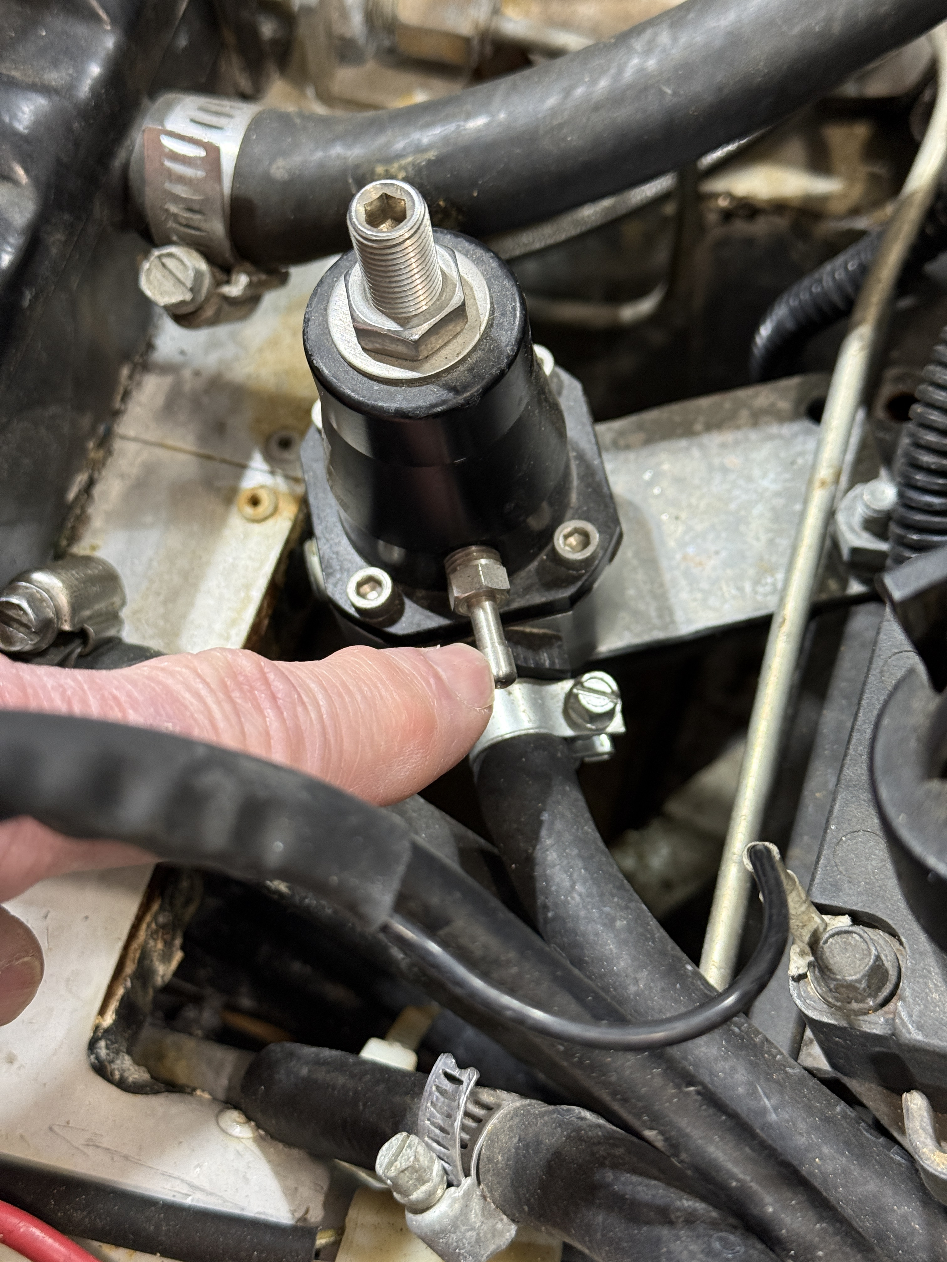
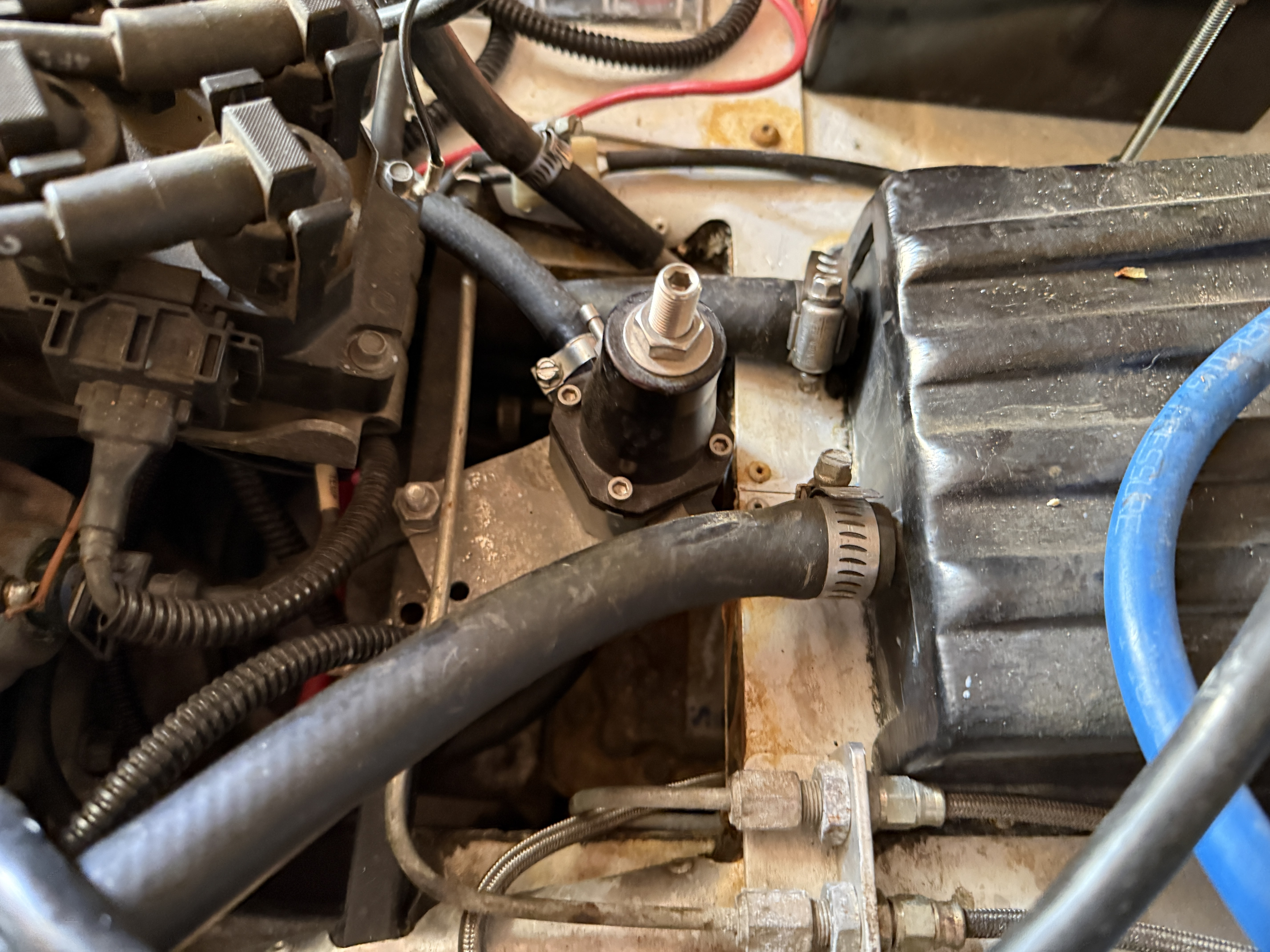
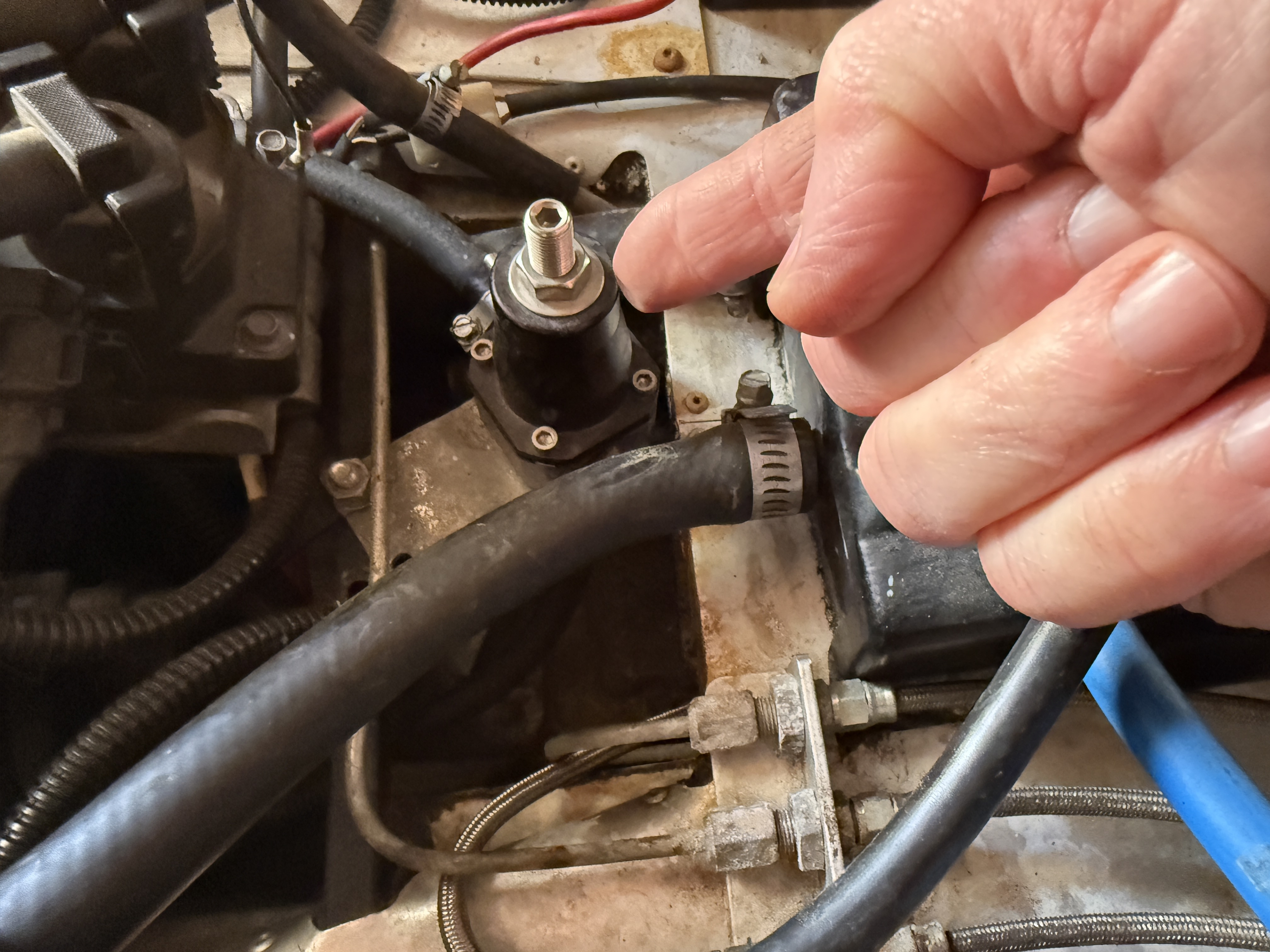
You all are correct. There is a hose straight down at the bottom of this device. I did not expect this to be fuel but I see now that it certainly is. From what I learned about connecting the Hayabusa injection on my Caterham, the fuel line comes from the fuel pump at the back of the car to the rear of the fuel rail. From the front of the fuel rail it goes to the fuel-pressure regulator and from there it goes to a return line back to the fuel tank. I noticed there is a small-diameter hose fitting on the fuel-pressure regulator with nothing attached to it. Since I see a similar fitting in in the photo from S1Steve, I expect this is nothing to worry about. Still, I am curious. What is the purpose of this little fitting?
-
Have you located these mounts? They are more like what I think might work or be more easily modified to fit my application. I am more than willing to make it worth your while to find them.
-
I can see that these will not work for my car, thank-you for the photos.
-
Basically the same regulator. Take a better look and you’ll see the second hose outlet at the bottom..
-
Faster. I never drove the car with the fast rack, but on a road course I can't image needing anything faster than the normal ratio.
-
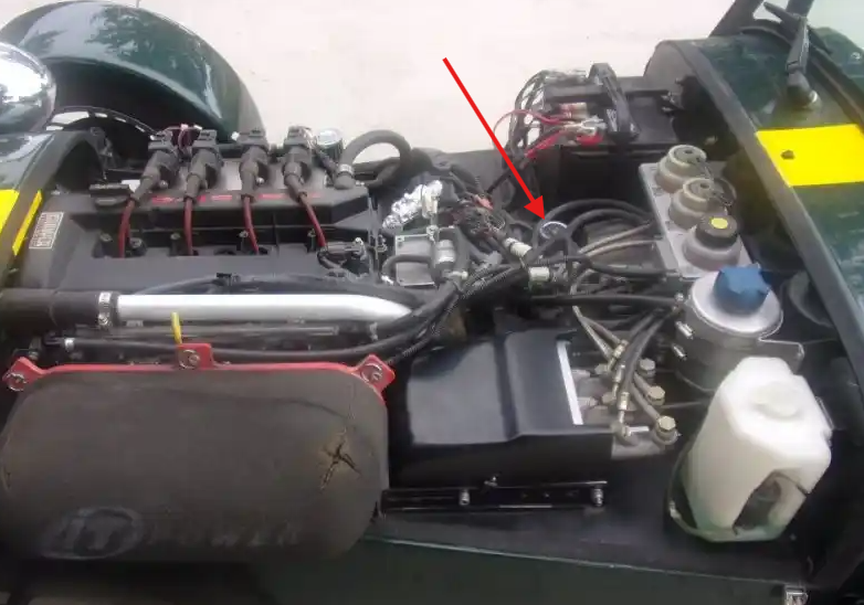
For what its worth, with my Birkin having a Duratec and my FPR a different unit, the location is the same as yours: This is an old picture I pulled from my other thread, with an arrow added to point out the FPR.
-
It certainly appears to be a regulator, and fuel makes the most sense. But it also appears as though only one of the barbed tubes is connected to a rubber line. That seems odd if fuel is going through it. Is there a third connection, perhaps on the underside?
-
It looks like the same FPR I ran in my fuel injected Birkin. I think mine was an Aeromotive.
-
 clarexinnusa joined the community
 -
In case it matters, this Birkin is fuel-injected.
-
FPR? edit: Fuel Pressure Regulator?
-
I'm York area, so not too far. Let me do some measurements and get back. Pics came through fine.
-
@Vovchandr is right. An adjustable FPR. Scott
-
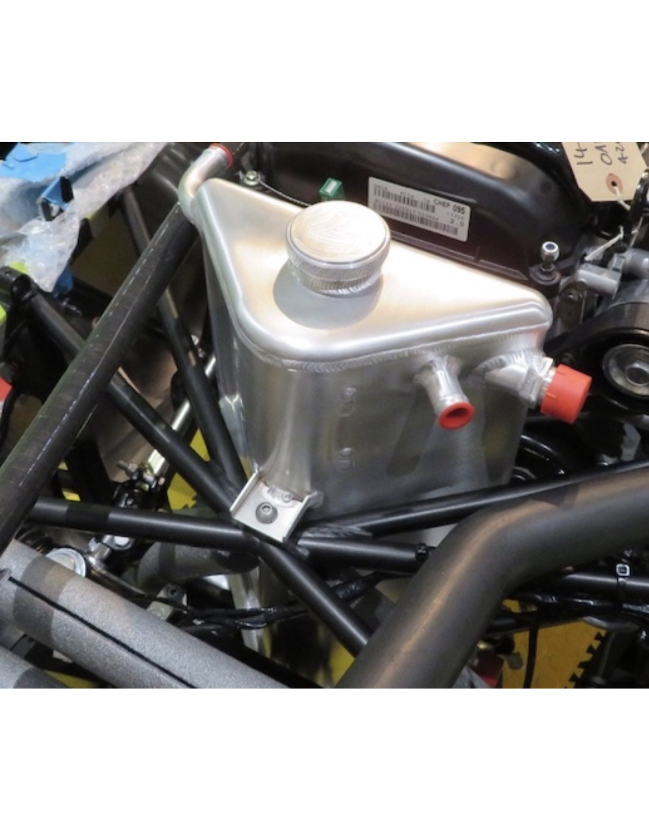
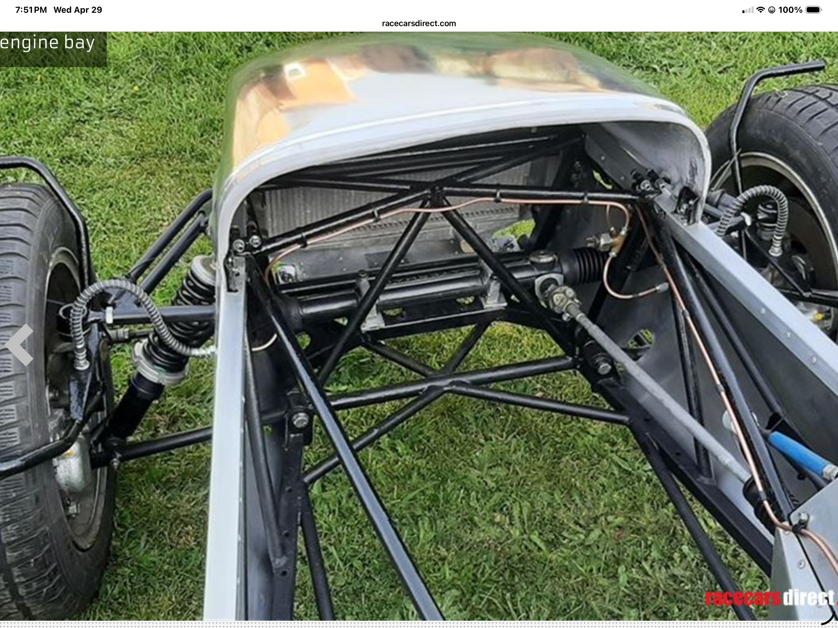
Thanks everyone for your comments/feedback. I also reached out to Caterham and asked the question and no response so far. Does anyone have the dimensions of that tank? If I had that I can do some measuring. From the photos I have found, the chassis tubes in front of the engine timing cover is similar in design except that newer frames have a hole where the chassis tubes meet for the tank to mount to. I haven't checked mine to see if it has that. I'm using the photos below without permission, the one with the tank pictured comes from https://www.caterham7diaries.com/post/dry-sump-tank-install The one of the imperial chassis... from racecars direct. Issues with the tank in front of the engine aside, I'd prefer the ease of that over modifying the passenger footwell, which I believe I'd have to do on my car to get a tank there. I did reach out to some local folks today and I could have a triangular tank fabricated for far less than the 900uk, plus shipping and tariffs (ouch). I think a triangular design using .125" aluminum sheet without the curves would be easy to draw up in Fusion 360 and the aluminum bungs/fittings are available at a variety of places on the internet. The only concern would be proper oil/air separation. The Caterham tank appears to deal with that with internal plates, probably drilled or slotted, for the oil to flow down through. Thanks, Scott
- Yesterday
-
That's what we're all here to find out.
-
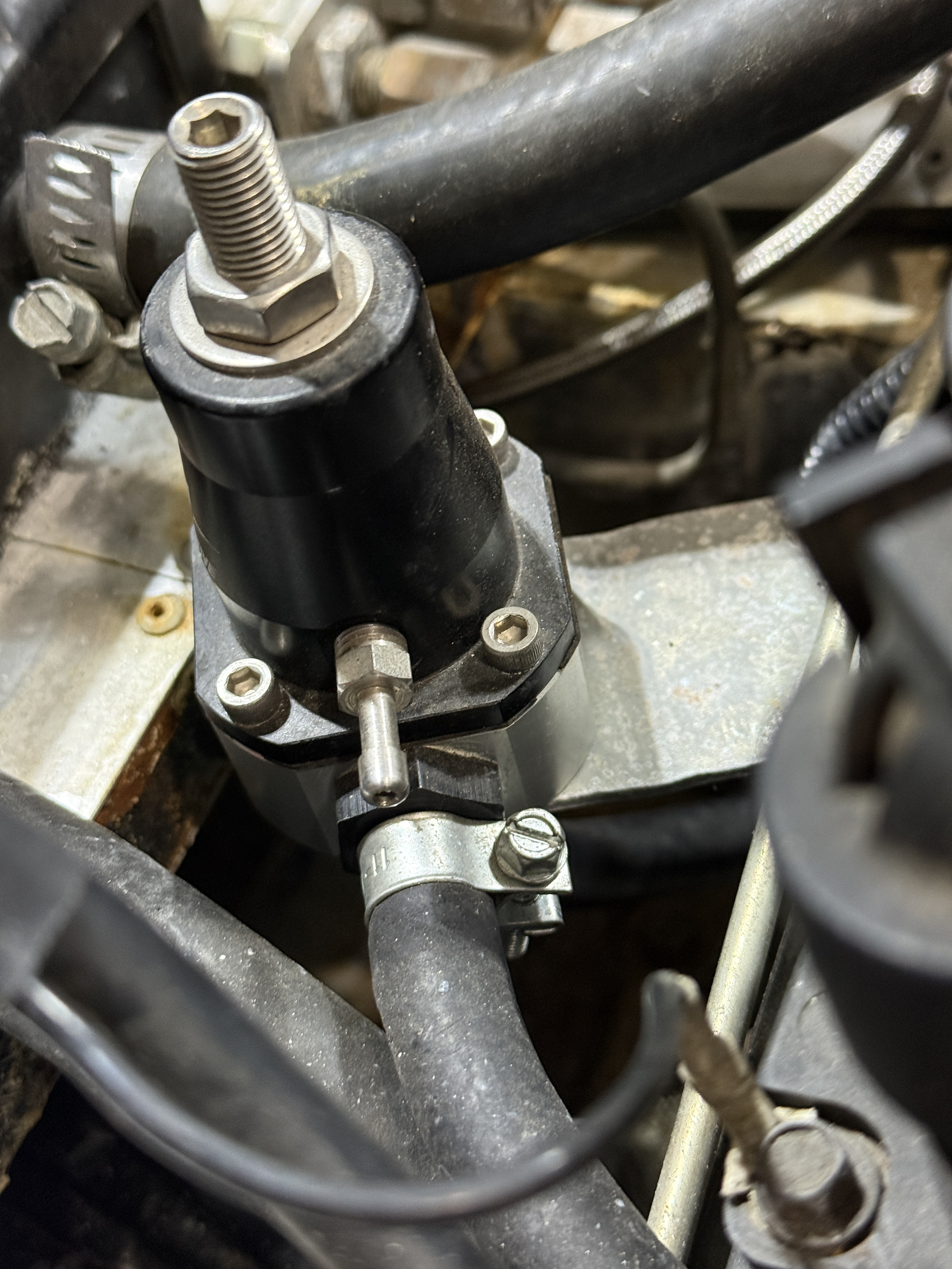
Are those fuel lines? Is that an FPR?
-
I need to know what this device is. Is it for controlling the heater? I'm standing on the left side of a 2003(?) Birkin with the Zetec engine, so the left side of the photo is towards the front of the car. On the left of these photos are the spark-plug wires heading forward to the engine. On the right of these photos is the heater core with two heater hoses coming out of it. In the middle of these photos is the gizmo I want to identify. It's in my way. If it is needed only for the heater, I would like to make it go away. I do not need a working heater. I can bag it and tag it.
-
see below
-
So, you are saying that the Caterham triangular dry sump tank will fit in front of a Duratec in a S3 imperial chassis?
-
The footwell tank can be bought but would require other engineering/plumbing solutions that are already solved by using the Caterham setup. Assuming it fits in his imperial chassis, everything would be plug and play. Maybe I'm just lazy and I hate modifying stuff. But it seems any improvised solution can trigger a set of unintended consequences and further troubleshooting.