MV8
-
Posts
2,303 -
Joined
Content Type
Profiles
Forums
Store
Articles
Gallery
Events
Library
Everything posted by MV8
-
Understood. Looks like a fun project. Looks like you had no issue posting your pics here. I think Jack's post was about locostusa and not a build log here. To keep things simple/compatible, I use a dedicated digital camera (old Canon SD1300) for taking pics and ms office 2010 (with an older OS) for a good editor. Everything else is too proprietary imho.
-
It depends on what model stalker you have and what aspect of the braking you wish to upgrade. Some pics would help. I'll guess that you have chevy S10 spindles, rotors, and single piston floating calipers with braided hoses and the concern is pedal effort. Stalkers have been around a long time so it could just need maintenance.
-
I'd check the nut major clearance at full droop, then shave the lower, big end of the lower spacer so the threads protrude from the full height nut lock. As long as the nut "teeth" clear the lca boss at full droop, it's fine. A socket would not be used at full droop. I would not swap for the half height/strength/engagement fender stay nuts but it probably works well enough. How thick is the nut? SAE 1/2 inch grade 8 nylock nuts are typically 0.593" thick. Older models have a specially made lower spacer/nut versus two pieces.
-
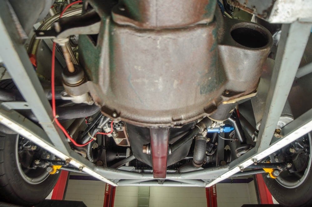
I think you have some damaged tripods inside the inner cv cups of the halfshafts but the diff is probably fine. Have you been bottoming out or getting airborne in the back end? Either way it is possible to damage the inners within the cups if the axles were designed slightly too long under some alignment specs and excess vertical travel. If that's the case you could just limit travel a little. The clamps and boots can be reused if your careful taking it apart to inspect.
-
I believe it would be the same as a 1963-1980 Triumph Spitfire for the inner, outer, and seal.
-
I'd make sure the trans vent is clear so pressure can't build and force oil out somewhere else, clean everything, refill, run hard briefly and recheck so you can catch it starting to leak and find the source.
-
It looks like TEAE went to a commendable amount of effort to perform a wide range of tests in a short period of time, but a chart with no supporting data is easy to debate, leaving more questions than answers but FWIW, I agree with most of it. I'm no stranger to trying to cool an SBF in a confined space. Police cars typically have mods that include restriction washers in the bypass, contrary to the tiger findings for the same family of ford engine, as does oem documentation (gm) on modification (of gm engines) for endurance racing.
-
The slip yoke rides on a long bushing in the tail housing that requires splash like the rest of the box. With an irs, it doesn't need any since there is no plunging with suspension movement. The tailhousing has a press-in seal around the driveshaft slip yoke. You probably just need to tap in a new seal. If you ever have a speed based (versus rpm) drive line vibration, the bushing can be damaged. The vibe could be the driveshaft joint angles could be setup wrong (pinion angle versus trans output shaft angle) or the drive shaft needs to be trued and balanced by a driveshaft machine shop. I usually take a shaft to a heavy truck shop where they do that type of work all the time. New joints, tubing, and balancing is typically about $200 for same day service.
-
There are a number of factors that make up what is a net improvement in heat transfer. The amount of heat transferred is directly proportional to the mass flow, temp delta across the exchanger (coolant versus air), and the time frame across it. If the pump pressure is increased (with design improvement or pulley ratio changes) or the restrictions reduced (staying out of cavitation), the mass flow will increase and the pressure will increase at the exchanger inlet. The cycle time of a drop of coolant across the exchanger is reduced but there are more passes for a given period. The temps across the entire system will be more uniform as well.
-
Their recommendation to leave it out and why makes sense but we have better options these days. The faster a given amount of coolant circulates, the more efficient the cooling system will be (i.e, more radiator passes in a period of time for the same heat load). If the coolant flow is too rapid for the passages, destructive cavitation can essentially erode the hard parts like the pump body, timing cover, impeller, etc but the stat is not the most restrictive element so I don't see the harm in that except for potentially slower warm up with a substantial cooling system. Ambient would also be a factor. I am not suggesting that anybody do this, but the greatest restrictions are the holes in the head gasket. In general, these are typically enlarged for endurance racing with pump and passage improvements for higher flow. A tiny change makes a big difference. There should be a bypass passage other than the heater circuit that can be completely closed. This can be a drilled stat, sometimes a small hose near the pump, or an internal passage or poor fitting stat. The bypass prevents hot spots during warm up. The amount bypassed is directly proportional to the level of numpty behind the wheel. Old cars with carbs have a built in safety of not running so well cold. Modern cars don't stop a person from abusing the cold equipment. All bypasses bypass the radiator and provide no cooling. I generally restrict the bypass, run a 180 stat, ensure the rad has baffles, and fit the biggest electric fan with the most amps I can find with a toggle and a thermo switch relay control.
-
It looked to me from the available pics that the lower column lateral location was the issue. Did they kick it out to the side for header clearance?
-
Weatherstripping adhesive. The older, smelly yellow type is better but might bleed through the fabric. Remove all the loose bits with a nylon scrub brush or better yet, replace the fabric. The patch can be sewn into new material. You could remove it entirely and take it to a upholstery to make a new one for you to glue on.
-
I use Ridesafely. Fewer fees than Copart at the same auctions.
-
They may be a little smaller. I think if the main case is far enough forward and at the right height, the bell size won't be an issue. However, since new bells are not rare or hard to find, you could cut and tig shut the offending bulges with 3/8 flat plate your welder can provide or possibly leave it open with a smooth, radiused edge. Depends on the details.
-
Sand casting in aluminum would be much easier. Most castings are rough because of the technique and grade of sand close to the mold. Fine detail can be transferred with no machining required except sprue removal. There is a small percentage of shrinkage as the part cools but the pattern could be printed or modded to be slightly oversize to compensate.
-
I think this is the first Cat I've seen with AC.
-

-
It sounds like you have the transmission set too far back. The engine should be far enough forward for the bell to clear the footbox. There is some variation in placement that I've seen in older caterhams. Some have the valve cover overlapped by the nose and the nose notched for carb clearance. Does the shifter opening in the tunnel align with the trans sitting on the mount?
-
Looks like the pedal box flanges are too far outboard, which put the box too far outboard, which suggested making the hole too far, etc. It looks like Westy put the flanges on based on a right hand drive dimensions. You said they didn't provide the top panel a few posts back. Maybe that is why? Ask Westy for the dimensions on where the rails should be on the chassis to confirm. I hope I am wrong. Take a pic of your foot well showing pedal lateral clearance. On other westy mx5 sevens, there should be an exhaust type U bolt clamp for the lower column. Between it and the upper mount should have the steering equidistant to the dash hoop on each side of the steering wheel. I don't know about anything special for an SV. Good pick about half way down the page: https://kitskitcar.wordpress.com/page/2/
-
Nice job. Looks like you are probably equipped to mill your own shims from bar stock instead of universals. Just shim up one side on the table and mill flat, then drill while still on the table. Looks like the upright should have some vertical slotting also to clear whatever angle the shanks end up at as a result of shimming so they don't bind with self-leveling washers for an even clamp load. Something like this: https://www.mcmaster.com/standard-washers/leveling-and-wave-washers/metric-leveling-washers-7/
-
I'd put normal pads back on the rear to see if that has any bearing on the expansion overflow issue. I'd rather fit an adjustable prop than the temp variable of special pads. Besides under car ducting and/or water misters, caliper pistons can be swapped for phenolic (if available) or insulated from the pad backing plate to reduce the heat transfer into the caliper body and fluid. The problem with phenolic is it can eventually swell from moisture absorption from irregular use and storage in a humid environment but that should not be an issue with a race car in a controlled environment.
-
A cable can be much longer lasting than a hydraulic system. I have 365k on a car with the original cable but I've been through many miata clutch masters and slaves with far fewer miles. The cable design could also be improved with three inches or so of semi-rigid sleeving support to make it more difficult to bend close to the shank shoulder and add years to the useful life of the cable.
-
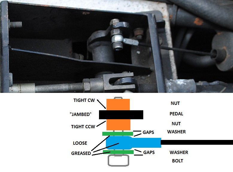
I think the main cause of early clutch cable failure is the pedal adjustment. Dr. Hasegawa was talking about that a few months ago. If the eye is not free to rotate, the cable will bend back and forth near the crimp, fatigue, and fail.
-
Which end locks up first? It sounds like the rear was upgraded with no changes to the front and/or balance adjustment to compensate. I don't know your car's history of modification and caterham doesn't share much info on parts used. There is an optimal curve for the overall combination that shows line pressure versus G in deceleration and it is a curve versus a straight line. To optimize the brake system, a balance bar and an adjustable proportioning valve is usually needed. Provide the following info and I'll do some calcs: Curb weight, front/rear balance, cg height (if you have it), tire size(s), brake rotor diameters, pad types, if the calipers slide/float (pistons on one side) or are fixed (pistons on both sides), number and precise size of pistons, and master cylinder bore size. With no pressure applied to the brake pedal, the piston in the master should be seated against the snap ring. This is to ensure the tiny compensation port is open. A brief squirt of a few cc's is normal and necessary for a self-bleeding master. If bleeding, leave the cap on loosely or roll slowly into the pedal to prevent the geyser.
-
In that case, after a run, I'd walk around checking the hubs for uniform heat from side to side with my palm. Maybe something is dragging (which can be hard to tell in such an overpowered machine) that is dumping more heat than normal into the fluid. Meanwhile, I'd run less than 50% in the reservoir and extend the bellows to displace some air over the fluid. I assume no brake lines are near the header or exhaust.