MV8
-
Posts
2,303 -
Joined
Content Type
Profiles
Forums
Store
Articles
Gallery
Events
Library
Everything posted by MV8
-

'89 Caterham electrical gremlins - indicators and flasher problems
MV8 replied to truckin-on's topic in General Tech
There are flashers with the same socket config but meant for different markets and are different internally. I'd go back to the original flasher to continue your troubleshooting. I suspect the ground wires need cleaning at the connections. Check resistance to the ground terminal of the battery to the engine block and chassis. It may help to post some pics at a distance of 2-3 feet of the engine bay, fuel pump or tank if in-tank, cowl, etc. I'll take a look at the schematics also. -
The lifted wheel is the result of roll. While the bar is trying to lift the inside wheel, it is not a 1:1 ratio even if there were no twist to the bar (infinitely thick bar) . The net result is less roll to net a lower inside wheel. The primary downside is "push". How much from a bar that increases roll stiffness by 75 lbs at most is anybody's guess, but this is a fairly cheap part, much easier to change than springs and is worth a try.
-
Do not use a 2 or 3 jaw puller. Use this kit with all the necessary bits. Clamp the knife-edged clam shells around evenly and not especially tight, then add the H bar and threaded rods to evenly pull it off. Grease the threads. Should pop back together on the hardened inner. No problem if you don't crease the inner dust ring trying to put it back in and it is not stretched, loosening the fit to the inner race od. Tap around the circumference to reinstall. https://www.ebay.com/itm/313569109324?_trkparms=amclksrc%3DITM%26aid%3D1110006%26algo%3DHOMESPLICE.SIM%26ao%3D1%26asc%3D241587%26meid%3D06ce783277ce462bae8c7562c757c419%26pid%3D101195%26rk%3D5%26rkt%3D12%26sd%3D312653842810%26itm%3D313569109324%26pmt%3D1%26noa%3D0%26pg%3D2047675%26algv%3DSimplAMLv11WebTrimmedV3MskuAspectsV202110NoVariantSeedKnnRecallV1%26brand%3D8milelake&_trksid=p2047675.c101195.m1851&amdata=cksum%3A31356910932406ce783277ce462bae8c7562c757c419|enc%3AAQAHAAABMMFr2e4EmAnM%2ByHZkULYKDIJ4L66fOjNL0iupgt%2BzO1%2F3AE1t3mNirUYB96NktMCicMagiS6mbeTl0xquGODv9mza5EI4qt7uNzzvEoOJav987%2B02NN%2Bku14aeBggJT5Kzvtke0lTQip37Buk3VGsP1PZLzoBPTxf9gIvHs9qf9hwoyihfBzHJMH9qKQZn2cIIjyJe3uzWbH%2FZhgRmP9otRo0aSc15mCLV1kN4RidMJZYZYzCRWywZ%2FUlRLbrJbm%2FkPyrs2QKBxrKerqejqvXAa3glpJ76vBenvlG6lnPlk6IzILL9aK%2BIEr2hBTDMPVgtdrUv8vsije2FHkEdRHdJnt3wwdn%2BmqrCT%2FK2g8Upw6jkBLYde71%2BLqwOPhn%2BqkzyWg%2FCYTipdm3qWxY4mGJMg%3D|ampid%3APL_CLK|clp%3A2047675&epid=23012962892
-
I'd go with the slightly larger front bar only and no other changes.
-
IMHO, if there is no course reversal or pull-back, Yes. If it is too late by then, it may be easier to take up residence in a more reasonable location for at least six months, title and register, then transfer when you move back.
-
The difference in thermal expansion between the thick weld and the thin cap and pressure is why it fails. Add a layer of silica cloth/mat/fabric to the inside of the cap. The material is similar to header wrap but you need one, wide piece to fit with no gaps. Cut the hole a little small to slip over the tube for a nice fit. Something like this: https://www.mcmaster.com/8827K25/ Might want to do both ends.
-
I've seen examples of blind studs pulled out and cars fall from the arms not being locked because the angle did not allow the pad to line up where it needed to go. Details in assembly and use are important. I'm sure wise, careful folks with mechanical ability should be able to use them safely. The neighbors kid fascinated by shiny objects that move, not so much.
-
If the bushing is lubricated, it doesn't matter. It's designed to slip/rotate instead of twist.
-
I'm not sure what you are saying? Unbonded need thrust surfaces to keep things centered laterally. Poly is not bonded.
-
I'd only tighten them when at ride height. Also, typical oem double bonded have a large to allow for the range or twist required without damage. I've noticed the rubber wall thickness is minimal on the Cats which would make it more critical. Tightening in droop would preload to raise the ride height but would probably settle after enough cycles.
-
An actual bushing is not bonded to the inner sleeve or outer tube so it doesn't matter (i.e. poly or nylon plastic). With a single-bonded "bushing" that is rubber and comes bonded to the inner sleeve, it is good practice to tighten at ride height but it isn't critical since it will slip at the outer shell. These are typically oem on Cats and triumphs from what I've seen. A double-bonded "bushing" is also bonded to the outer shell that presses into a tube in the control arm (i.e. most oem applications). They typically have teeth on the ends of the inner sleeve to bite into the chassis flanges when tightened to ensure there is no movement, only a few degrees of twist that it was designed for. They also provide some dampening. Tightening at full droop may cause the rubber to tear, crack, separate, etc sooner.
-
I don't think the case is going to be an issue. The contact area is so much greater with greater leverage than the inner race is to the axle so if something is going to slip, it should be the inner. You can put the axle in the freezer and the bearing on a cookie sheet for a 1/2 hour at 150f. After cool/heating, the axle/bearing assy could be placed in the freezer again but it should not be an issue. An alternative to welding the inner to the axle is to add a separate ring/sleeve to the axle as a shoulder, which could be tacked to the axle. If the bearing actually needs that much welding to stay in place, I'd fit a sleeve instead. A moot point, but a new axle does not have to be thicker to be more durable. Alloys like 300m are more spring-like than traditional alloys so they give/absorb more energy instead of transferring torque spikes that can shear (and cause a loss of traction). A well designed axle is thinner than the splined ends with a gradual taper and no grooves.
-
I'd cut the wrap and trace all the inputs to the pectel, then rearrange so the harness relies more on clamps than on the connections for support and leave a stress relief loop at the connectors. You can buy split loom or other type of cover instead of tape and just used a little tape every foot or so to keep it tight. Make a diagram of every connection to keep handy.
-
SLR Wheels are not MB Wheels/Engineering or Image Wheels
MV8 replied to 2001SLR's topic in General Sevens Discussion
Take a pipe inspecting camera (plugs into usb and has a light built in) on a rear wheel to inspect the inboard side of the spokes for markings. Should have the size, offset, country of origin, and mfg. -
I hope they used irs 8.8 side gears versus the standard straight axle gears, which have no groove to retain the stub snap ring. Easy to check if the axle is out for new rings.
-
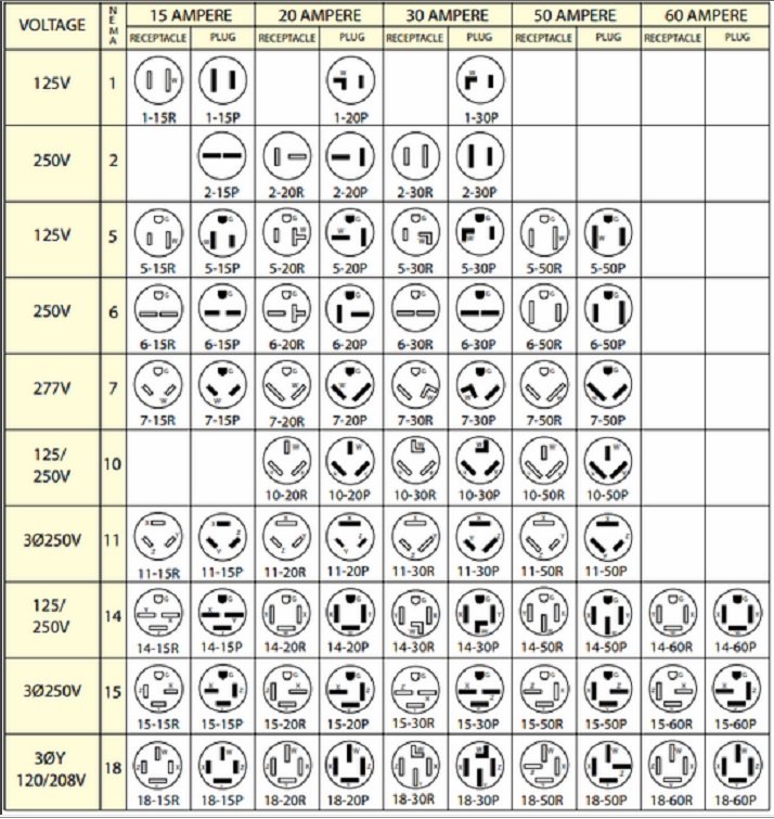
Great video. Along with the correct wiring for the amps, another thing to consider is changing to a NEMA approved plug and outlet for 30amps@110vac to prevent plugging in normal equipment in the same outlet and operating in the safety margin for the 20a plug. It may pull more amps after there is some wear and more friction. There are several configs including an RV type plug. It may be tempting to use a 220vac plug/recep with 110vac due to the improved capacity but it would be too easy to damage anything that may be plugged in down the road as well as against code. A 220vac system is a better option when 110vac amps exceed 20 so you'd need to rewire anyway. The amps are half as much, allowing a smaller, lighter motor design. I made an impulse purchase of an unusual plasma cutter that came with a standard 20a 110 plug but is designed to pull up to 29 amps. A 220 machine would have been a better choice. To use the 110/29, I made a dedicated circuit and swapped to half width breakers since the 220 feed aux panel in my home shop was full. Converting a few dozen 2x4 fluorescent fixtures to LED was a nice upgrade.

-
Pics: https://usa7s.net/ips/topic/13872-identifying-a-replica-“7”-project/#comment-128395 I'd buy it if I had space for it and was not so far away.
-
I expect the inner cup was not fully seated in the diff side gear when installed. I doubt the axle came out completely and just needs to be pushed in completely to seat the snap ring into the groove. Grab where the boots fits over the inner cup to push and wiggle it in, then compare the gap to the diff on the other side. No seal damage is likely if the inner cup didn't come out of the diff completely.
-
Thoughts: Deep, large area, concrete footings with fiber and rebar hooked or welded to the J-bolts (versus blind anchors) are a given. I would not consider a two post or just swinging arms for a cradle (which should engage both sides) for when things go wrong. An adjustable mechanical limit pin in the towers to prevent ever raising it too far for the car. Ratcheting locks that engage as it is extended so it cannot drop far from a hydraulic failure. Not air actuated which invites moisture inside (hidden rust). A single diagonal tube on each side from the top of one tower to the base of the other on that side would be nice.
-
Could always use an oem cable too with some pedal and housing adjustment/stop mods to accept the end clips or cut a used, long oem cable and reterminate. It's good that Flanders list the core for the housing. Unlike typical tolerances for most materials, the standard is that the size listed for wire rope is the minimum with the tolerances on the plus side, since they don't assume the rope will be in a conduit.
-
No experience with the Ital axle. It is common for wheel bearing failures to cause the inner race to spin on the axle, wearing down the axle. The result is usually a "tramp" at highway speeds, like going over rumble strips that are spaced apart. There have been sleeves and special bearings used to move the bearing centering inboard, away from the worn area. Hopefully the bearing was tacked on a good axle that requires some effort to press the bearing on, ensuring it is centered. The tack or stitch weld can be cut to replace the bearing using a lathe or friction disc. If the axle is worn, it can be built back up, rough machined, heat treated, then final machined to spec. Instead of repair, you can also have a new axle shaft made from better material. I've ordered custom axles from Moser Engineering with broaching service from Mark Williams. Probably the most cost effective thing would be probably be to convert to a more durable and common Caterham axle from that era but I don't know if they have the same attachment points and there may be a driveshaft component change as well.
-
7x7 is a good all around core for flexibility, friction, tensile, stretch resistance, etc. More wires= more flexible=more friction in the housing. Thicker=less flexible, higher capacity for less stretch (which is really the tiny gaps between the wires tightening up). If soldering the ends versus crimping or a wedge type termination, galvanized is easier than stainless which requires an acid treatment for wetting/tinning. Round or flat wire bowden housing doesn't matter if a liner is used. Nylon tube is also an effective liner and the wire can be coated as well. Preloading to 60% strength is worth the price difference so the cable won't need to be reterminated after a few days use if the cable is especially thin for the pedal loading.
-
The Regular Summary of Classified Ads of Se7ens Found For Sale
MV8 replied to Croc's topic in Cars For Sale
Probably the energy of the auction had waned. I've known Kurt for a long time. I've never seen him do poor work. He's also an EE which requires some ME skills. -
I agree with the tractor repairman. It wasn't clear what you had ordered that was "bigger".
-
SLR Wheels are not MB Wheels/Engineering or Image Wheels
MV8 replied to 2001SLR's topic in General Sevens Discussion
Looks like some tube and four half-rounds would do it. Insert, tape or tack together, remove and braze or weld to the tube an inch from the end, then cross drill the the other end for a T-handle. Probably need to make the half rounds by grinding rods. Looks like they may be 1/4 inch rods? You could also make a paper transfer, cut it out then trace over the end of a rod big enough to cover the entire relief (1/2-5/8"?) then grind and bore as needed to fit.